EMOIBT230Bluetooth Wireless FM Clock Radio with USB Charging
SDI Technologies Inc.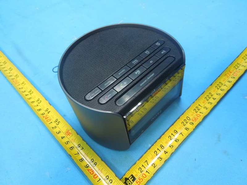
Click to zoom
Application Details
- Equipment Class
- DSS - Part 15 Spread Spectrum Transmitter
- Date of Grant
- Dec 07, 2014
- Application Purpose
- Original Equipment
- Date of Application
- Dec 07, 2014
- Equipment Note
- Bluetooth Wireless FM Clock Radio with USB Charging
- Frequency Range
- 2402.00000000 - 2480.00000000
- Company
- SDI Technologies Inc.
- Country
- United States
Documents & Files
Document Text
Text extracted from the exhibit documents filed with the FCC. Open a document above to read the original.
Users Manual
Model: iBT230 instruction manual iBT230 Eng IB Size: 153mm x 120mm Printing color: Black Nov 4, 2014 P1 Bluetooth Wireless FM Clock Radio with USB Charging Questions? Contact Customer Service at 1-800-288-2792 iBT230 Introduction Thank you for purchasing the iHome iBT230. This product is designed to provide high quality wireless sound for your iPad, iPhone, iPod or other Bluetooth audio device. This instruction booklet explains the basic operation and care of the unit. Please read it carefully and keep for future reference. • Place the unit on a level surface away from sources of direct sunlight or excessive heat. • Protect your furniture when placing your unit on a natural wood and lacquered finish. A cloth or other protective material should be placed between it and the furniture. • Clean your unit with a soft cloth moistened only with mild soap and water. Stronger cleaning agents, such as benzene, thinner or similar materials can damage the surface of the unit. 1 P2 Maintenance iBT230 Table of Contents 2 What’s Included ...............................................................................................................3 Meet Your iBT230 ............................................................................................................4 The Display/Setting Up the Unit ..........................................................................................5 Replacing/Installing Backup Batteries ...................................................................................6 Setting the Clock .............................................................................................................7 Setting and Using the Alarms/Previewing Alarm.................................................................. 7-8 Snooze/Display Dimmer Button/Sleep Mode/FM Radio.........................................................9 Setting and Using FM Presets/Using FM Radio in Other Countries ...........................................10 Pairing Your Bluetooth Device ..........................................................................................11 Playing Audio Via Bluetooth..............................................................................................12 Using the Speakerphone feature ........................................................................................12 Playing Audio Via Aux-in .................................................................................................13 Charging Devices via USB Port .........................................................................................14 Battery Use Cautions and Tips..........................................................................................15 Troubleshooting ..............................................................................................................16 Consumer Product Safety Guide ........................................................................................17 FCC information.............................................................................................................18 Warranty......................................................................................................................19 P3 iBT230 3 P4 What’s Included • iBT230 system • 100V-240V universal AC adaptor • Stereo audio cable power adaptor audio cable iBT230 pair iBT230 P5 Meet Your iBT230 Top 4 Backup Battery Compartment Bottom Back DC Jack USB Charging Port Aux-in Jack FM Antenna DC 5V 2A Answer Call/ Plus Settings Button Mode Button Presets Button Volume Down/ Volume Up Buttons Snooze/Display Dimmer Button Alarm 1 Button Alarm 2 Button Sleep/Clock Adjust Button Power/ Alarm Reset Button End Call/ Minus Settings Button Play/Pause/Pairing Button pair iBT230 Using the The Display 5 P6 Alarm Active Indicator Aux-in Mode Indicator Set Wake-to Sleep Mode Indicator FM Radio Mode Indicator Bluetooth/Pairing Indicator PM/AM Indicators Alarm Time/Date/Radio Frequency Wake to source: BT (Bluetooth), FM Radio, Buzzer Mode: BT (Bluetooth), FM Radio, Aux Time Display Low Backup Battery Indicator DC 5V 2A FM antenna RESET RESET TEST TEST Setting Up the Unit Connect the included AC adaptor to the DC jack located on the back of the unit and connect the other end to a working wall outlet. Extend FM antenna. 2 AA batteries are included for battery backup. Install them in the backup battery compartment located on the bottom of the unit before using the unit. See page14 for more on installing and replacing backup batteries. P7 6 Using the iBT230 Replacing and Installing Clock Backup Batteries Note: 2 AA batteries are included with the unit. Install them before using the unit. This model is equipped with a battery backup circuit that will maintain the time and alarm time settings in the event of a temporary power interruption (the display is NOT maintained). The battery backup circuit will also operate the buzzer alarm to wake you up at the selected wake up time even if the power is out. When the backup batteries are getting weak the Low Backup Battery Indicator will begin flashing in the display. When you see this flashing indicator you should replace the backup batteries as soon as possible. Note: We recommend alkaline batteries for best performance. To install/replace the backup batteries: IMPORTANT: When replacing the backup batteries be sure to have the unit connected to the AC outlet to maintain all of your settings, otherwise it will be necessary to reset the time and alarm time after the batteries are replaced. 1. Slide and remove the battery door located on the bottom of the unit. If replacing batteries, remove the exhausted batteries. 2. Insert 2 fresh AA batteries in the backup battery compartment. Make sure the polarity of the batteries (“+” or “-” nodes) matches the illustration. 3. Slide and close the battery compartment door. Confirm that the backup battery indicator is not flashing in the display. Note: Make sure you dispose of batteries properl…
Text truncated - open the document above for the full version.
External Photos
Project No.: 1411C141 Page 2 of 9 Project No.: 1411C141 Page 3 of 9 Project No.: 1411C141 Page 4 of 9
ID Label/Location Info
This device complies with Part 15 of the FCC Rules. Operation is subject to the following two conditions: (1) This device may not cause harmful interference, and (2) this device must accept any interference received, including interference that may cause undesired operation. CAN ICES-3 (B)/NMB-3(B) iBT230 bottom engraving 0.4mm Sclae : 1:1 Sept 12, 2014 iBT230 2013 2014 2015 2016 2017 iBT230 2013 2014 2015 2016 2017 iB T230 model plate Sept 12, 2014 PVC cut sheet color: ref er to DL FM 87.5 - 107.9 MHz DC 3V, AA x 2 DC 5V, 2A iB T230-A-A Frequency Range: Clock Backup: AC Adaptor : Ser vice Number: Manufactured and Serviced by SDI Technologies Inc. Designed in the USA Pat ents: www.ihome.com/patents Toll Free: 1-800-288-2792 Made in China www.ihome.com FCC ID: EMOIBT230 IC: 986B-IBT230 iBT230 DC 1.5V "AA" UM-3, LR6 SIZE DC 1.5V "AA" UM-3, LR6 SIZE OPEN iBT230 Battery door engraving 0.4mm Sclae : 1:1 Sept 10, 2014
Internal Photos
Project No.: 1411C141 Page 5 of 9 Project No.: 1411C141 Page 6 of 9 Project No.: 1411C141 Page 7 of 9 Project No.: 1411C141 Page 8 of 9 Project No.: 1411C141 Page 9 of 9
Test Report
Report No.: BTL-FICP-1-1411C141 Page 1 of 109 FCC&IC Radio Test Report FCC ID: EMOIBT230 IC: 986B-IBT230 This report concerns (check one): Original Grant Class II Change Project No. : 1411C141 Equipment : Bluetooth Wireless FM Clock Radio with USB Charging Model Name For FCC : iBT230 ; iBT230X, iBT230XC (“X”= a to Z; denote as color of cabinet) Model Name For IC : iBT230 Applicant : SDI TECHNOLOGIES INC. Address : 1299 Main Street, Rahway, NJ 07065, U.S.A Date of Receipt : Nov. 14, 2014 Date of Test : Nov. 14, 2014~Nov. 21, 2014 Issued Date : Nov. 24, 2014 Tested by : BTL Inc. Testing Engineer : (David Mao) Technical Manager : (Leo Hung) Authorized Signatory : (Steven Lu) BTL INC. No.3, Jinshagang 1st Road, Shixia, Dalang Town, Dongguan, Guangdong, China. TEL: +86-769-8318-3000 FAX: +86-769-8319-6000 Report No.: BTL-FICP-1-1411C141 Page 2 of 109 Declaration BTL represents to the client that testing is done in accordance with standard procedures as applicable and that test instruments used has been calibrated with the standards traceable to National Measurement Laboratory (NML) of CHINA, or National Institute of Standards and Technology (NIST) of U.S.A. BTL's reports apply only to the specific samples tested under conditions. It is manufacture’s responsibility to ensure that additional production units of this model are manufactured with the identical electrical and mechanical components. BTL shall have no liability for any declarations, inferences or generalizations drawn by the client or others from BTL issued reports. BTL’s reports must not be used by the client to claim product endorsement by the authorities or any agency of the Government. This report is the confidential property of the client. As a mutual protection to the clients, the public and BTL-self, extracts from the test report shall not be reproduced except in full with BTL’s authorized written approval. BTL’s laboratory quality assurance procedures are in compliance with the ISO Guide 17025 requirements, and accredited by the conformity assessment authorities listed in this test report. Limitation For the use of the authority's logo is limited unless the Test Standard(s)/Scope(s)/Item(s) mentioned in this test report is (are) included in the conformity assessment authorities acceptance respective. Report No.: BTL-FICP-1-1411C141 Page 3 of 109 Table of Contents Page 1 . CERTIFICATION 7 2 . SUMMARY OF TEST RESULTS 8 2.1 TEST FACILITY 9 2.2 MEASUREMENT UNCERTAINTY 9 3 . GENERAL INFORMATION 10 3.1 GENERAL DESCRIPTION OF EUT 10 3.2 DESCRIPTION OF TEST MODES 12 3.3 TABLE OF PARAMETERS OF TEXT SOFTWARE SETTING 12 3.4 BLOCK DIAGRAM SHOWING THE CONFIGURATION OF SYSTEM TESTED 13 3.5 DESCRIPTION OF SUPPORT UNITS 13 4 . EMC EMISSION TEST 14 4.1 CONDUCTED EMISSION MEASUREMENT 14 4.1.1 POWER LINE CONDUCTED EMISSION LIMITS 14 4.1.2 TEST PROCEDURE 14 4.1.3 DEVIATION FROM TEST STANDARD 14 4.1.4 TEST SETUP 15 4.1.5 EUT OPERATING CONDITIONS 15 4.1.6 EUT TEST CONDITIONS 15 4.1.7 TEST RESULTS 15 4.2 RADIATED EMISSION MEASUREMENT 16 4.2.1 RADIATED EMISSION LIMITS 16 4.2.2 TEST PROCEDURE 17 4.2.3 DEVIATION FROM TEST STANDARD 17 4.2.4 TEST SETUP 18 4.2.5 EUT OPERATING CONDITIONS 19 4.2.6 EUT TEST CONDITIONS 19 4.2.7 TEST RESULTS (9KHZ TO 30MHZ) 19 4.2.8 TEST RESULTS (BETWEEN 30MHZ TO 1000 MHZ) 20 4.2.9 TEST RESULTS (ABOVE 1000 MHZ) 20 5 . NUMBER OF HOPPING CHANNEL 21 5.1 APPLIED PROCEDURES 21 5.1.1 TEST PROCEDURE 21 5.1.2 DEVIATION FROM STANDARD 21 5.1.3 TEST SETUP 21 5.1.4 EUT OPERATION CONDITIONS 21 5.1.5 EUT TEST CONDITIONS 21 5.1.6 TEST RESULTS 21 Report No.: BTL-FICP-1-1411C141 Page 4 of 109 Table of Contents Page 6 . AVERAGE TIME OF OCCUPANCY 22 6.1 APPLIED PROCEDURES / LIMIT 22 6.1.1 TEST PROCEDURE 22 6.1.2 DEVIATION FROM STANDARD 22 6.1.3 TEST SETUP 22 6.1.4 EUT OPERATION CONDITIONS 23 6.1.5 EUT TEST CONDITIONS 23 6.1.6 TEST RESULTS 23 7 . HOPPING CHANNEL SEPARATION MEASUREMENT 24 7.1 APPLIED PROCEDURES / LIMIT 24 7.1.1 TEST PROCEDURE 24 7.1.2 DEVIATION FROM STANDARD 24 7.1.3 TEST SETUP 24 7.1.4 EUT TEST CONDITIONS 24 7.1.5 TEST RESULTS 24 8 . BANDWIDTH TEST 25 8.1 APPLIED PROCEDURES 25 8.1.1 TEST PROCEDURE 25 8.1.2 DEVIATION FROM STANDARD 25 8.1.3 TEST SETUP 25 8.1.4 EUT OPERATION CONDITIONS 25 8.1.5 EUT TEST CONDITIONS 25 8.1.6 TEST RESULTS 25 9 . PEAK OUTPUT POWER TEST 26 9.1 APPLIED PROCEDURES / LIMIT 26 9.1.1 TEST PROCEDURE 26 9.1.2 DEVIATION FROM STANDARD 26 9.1.3 TEST SETUP 26 9.1.4 EUT OPERATION CONDITIONS 26 9.1.5 EUT TEST CONDITIONS 26 9.1.6 TEST RESULTS 26 10 . ANTENNA CONDUCTED SPURIOUS EMISSION 27 10.1 APPLIED PROCEDURES / LIMIT 27 10.1.1 TEST PROCEDURE 27 10.1.2 DEVIATION FROM STANDARD 27 10.1.3 TEST SETUP 27 10.1.4 EUT OPERATION CONDITIONS 27 10.1.5 EUT TEST CONDITIONS 27 10.1.6 TEST RESULTS 27 11 . MEASUREMENT INSTRUMENTS LIST 28 Report No.: BTL-FICP-1-1411C141 Page 5 of 109 Table of Contents Page 12 . EUT TEST PHOTO 30 ATTACHMENT A - CONDUCTED EMISSION 34 ATTACHMENT B - RADIATED EMISSION (9KHZ-30MHZ) 37 ATTACHMENT C - RADIATED EMISSION (30MHZ TO 1000MHZ) 39 ATTACHMENT D - RADIATED EMISSION (ABOVE 1000MHZ) 46 ATTACHMENT E - NUMBER OF HOPPING CHANNEL 71 ATTACHMENT F - AVERAGE TIME OF OCCUPANCY 73 ATTACHMENT G - HOPPING CHANNEL SEPARATION MEASUREMENT 86 ATTACHMENT H - BANDWIDTH 91 ATTACHMENT I - PEAK OUTPUT POWER 96 ATTACHMENT J - ANTENNA CONDUCTED SPURIOUS EMISSION 101 Report No.: BTL-FICP-1-1411C141 Page 6 of 109 REPORT ISSUED HISTORY Issued No. Description Issued Date BTL-FICP-1-1411C141 Original Issue. Nov. 24, 2014 Report No.: BTL-FICP-1-1411C141 Page 7 of 109 1. CERTIFICATION Equipment : Bluetooth Wireless FM Clock Radio with USB Charging Brand Name : iHome Model Name For FCC : iBT230 ; iBT230X, iBT230XC (“X”= a to Z; denote as color of cabinet) Model Name For IC : iBT230 Applicant SDI TECHNOLOGIES INC. Manufacturer : SDI TECHNOLOGIES INC. Address : 1299 Main Street, Rahway, NJ 07065, U.S.A Factory : Jadestar Electronics (Shenzhen) Co. Ltd. Address : Block 5, He Tai Industrial Zone, He Ping Community, Fu Yuan Town, Bao…
Text truncated - open the document above for the full version.
Test Setup Photos
Report No.: BTL-FICP-1-1411C141 Page 30 of 109 12. EUT TEST PHOTO Conducted Measurement Photos Report No.: BTL-FICP-1-1411C141 Page 31 of 109 Radiated Measurement Photos 9KHz to 30MHz Report No.: BTL-FICP-1-1411C141 Page 32 of 109 Radiated Measurement Photos 30MHz to 1000MHz Report No.: BTL-FICP-1-1411C141 Page 33 of 109 Radiated Measurement Photos Above 1000MHz
Contact Information
Applicant
David Stetin(Compliance Officer)
Test Firm
BTL Inc.Daisy Dai
Technical Specifications
| # | Rule Parts | Frequency Range | Power Output |
|---|---|---|---|
| 1 | 15C | 2.40 GHz - 2.48 GHz | 2.00 mW |
Other Applications from SDI Technologies Inc.
EMOIPCV3A
May 27, 2026Magnetic Wallet Power Bank
Equipment Class
DCD - Part 15 Low Power Transmitter Below 1705 kHz
EMOTW502A
Apr 22, 2026ALARM CLOCK WITH NIGHTLIGHT AND FAST WIRELESS CHARGING
Equipment Class
DCD - Part 15 Low Power Transmitter Below 1705 kHz
EMO555B
Nov 23, 2025Bluetooth Karaoke
Equipment Class
DSS - Part 15 Spread Spectrum Transmitter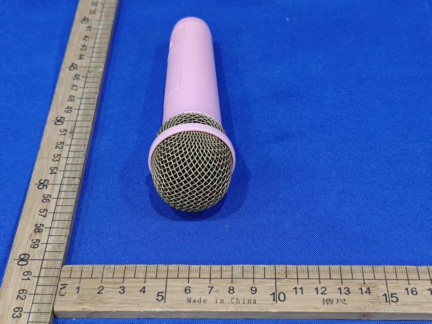
EMO555BM
Nov 23, 2025Bluetooth Karaoke
Equipment Class
DTS - Digital Transmission System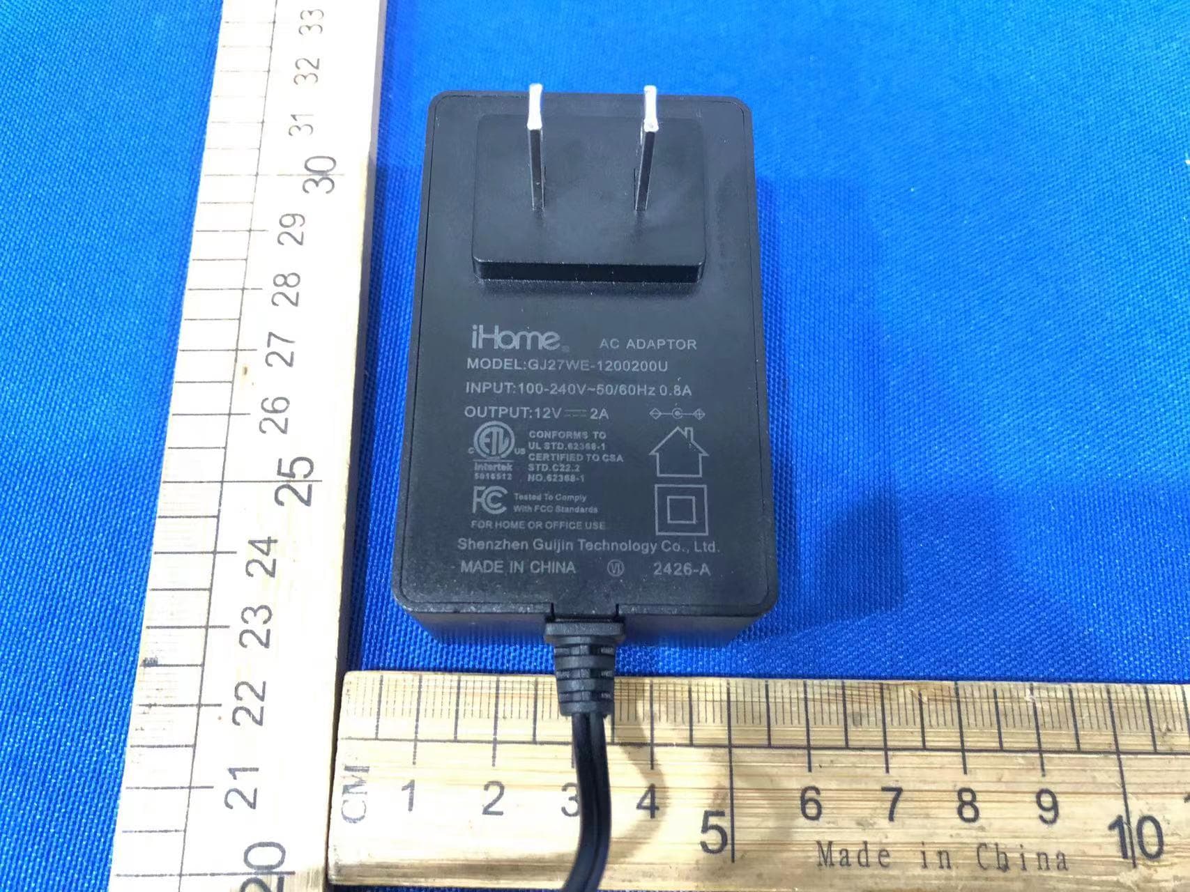
EMOIBTW112A
Sep 07, 2024Bluetooth Alarm Clock with wireless and USB charging
Equipment Class
DSS - Part 15 Spread Spectrum Transmitter