EMOT331Bluetooth Dual Alarm AM/FM Clock Radio
SDI Technologies Inc.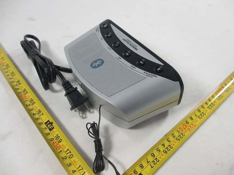
Click to zoom
Application Details
- Equipment Class
- DSS - Part 15 Spread Spectrum Transmitter
- Date of Grant
- Jan 22, 2014
- Application Purpose
- Original Equipment
- Date of Application
- Jan 22, 2014
- Equipment Note
- Bluetooth Dual Alarm AM/FM Clock Radio
- Frequency Range
- 2402.00000000 - 2480.00000000
- Company
- SDI Technologies Inc.
- Country
- United States
Documents & Files
Document Text
Text extracted from the exhibit documents filed with the FCC. Open a document above to read the original.
Users Manual
Model: T331 IB (English Version) Color : Black text on white paper Size: 120 W x 170 H mm (folded) Date: Jan. 16, 2014 NOTE: You must make the time and alarm time adjustments while the display is flashing. If no adjustments are made for approximately 8 seconds the display will stop flashing and cannot be adjusted. If this occurs you must start the time and alarm setting procedure again and make sure that you complete the adjustments while the display is flashing. Radio Operation POWER/MODE Button – When the unit is ‘off’ press the MODE/ALM RESET button repeatedly to select the following operating modes: First Press – FM Radio band. The initial default display is 87.5 mHz. Second Press – AM Radio band. The initial default display is 520 kHz. Third Press – AUX (AUH) mode. To listen to an external audio source. Fourth Press – Bluetooth Mode. 1. Press the MODE/ALM RESET Button to turn the radio ‘on’ and select the FM band. The initial FM frequency display is 87.5 mHz. Press the MODE/ALM RESET Button again to select the AM band. The initial AM frequency display is 520 kHz. 2. After selecting the desired band tune to a radio station by either the automatic or manual tuning method: • Automatic Tuning – Press and hold the HOUR / or MIN / button until the frequency display begins to move, then release the button. The tuner will search up or down for the next strong station and stop on that station. Repeat this procedure until the tuner stops on the desired station. After a few seconds the display will change from the radio frequency back to the correct time. • Manual Tuning – Repeatedly press the HOUR / or MIN / button until the display shows the frequency of your desired station. Use the Manual Tuning method to tune to weaker stations that could be bypassed during automatic tuning. After a few seconds the display will change from the radio frequency back to the correct time. 3. Press the ALM 1 (VOL +) or ALM 2 (VOL -) button to adjust the radio volume level. The display changes to show the volume level indication (00 to 20) during volume adjustments, then changes back to the radio station frequency, and then the current time. 4. When you are finished listening press and hold the MODE/ALM RESET button until the display shows OFF, then release the button. The display will then return to the correct time. Last Station Memory The tuner remembers the last FM and AM station that you were listening to and automatically returns to those stations the next time you select the FM or AM mode. Preset Station Memory The tuner can store up to 10 FM and 10 AM station in memory for easy recall. To store a station in memory: 1. Tune to the first station that you wish to store using either the Automatic or Manual Tuning methods described above. 2. When the display is showing the frequency of the desired station, press and hold the CLOCK / PRESET / PAIR button until the “P 01” indicator begins flashing in the display. 3. Press the CLOCK / PRESET / PAIR button once more to store your station in Preset Memory number 1. The preset indicator will automatically advance to “P 02”. 4. Repeat steps 1 thru 3 until you have stored up to 10 stations of one band, then change bands and follow the same procedure to store up to 10 stations of the remaining band. Unwind the FM wire antenna and extend it to its full length. Unwind the AC power cord completely and insert the plug into a 120V/60Hz AC outlet. Use an outlet that is always ‘live’. Do not use an outlet that is controlled by a wall switch. When the clock is connected to the AC outlet for the first time the display will turn on and begin flashing “12:00 (PM)”. If you have not installed the back up batteries the Low Battery indicator will also appear in the display. Setting The Time NOTE: The time can only be set when the clock radio is in the OFF mode. If the radio is playing, press and hold the MODE/ALM RESET button until the display briefly shows ‘OFF’ and then reverts to the time. 1. If the display is flashing, press the HOUR / button to advance the display to the correct hour. If the display is not flashing press and hold the CLOCK button until the display begins to flash, then press the HOUR / button to advance the display to the correct hour. Observe the PM indicator to confirm that you have set the hour correctly. If the PM indicator is ‘On’ the hour on the display is PM. If the PM indicator does not appear the hour on the display is AM. 2. Press the MIN / button to advance the display to the correct minute. 3. When the correct time is flashing on the display press the CLOCK / PRESET / PAIR button once more. The display stops flashing and the clock begins to run. Setting The Alarm Time This Timex clock radio has dual alarms that can be set and used independently. The initial default alarm settings are 6:00 AM for Alarm 1 and 7:00 AM for Alarm 2. The procedure for setting both alarms is the same. NOTE: The alarm times can only be adjusted when the clock radio is in the OFF mode. If the radio is playing, press and hold the MODE/ALM RESET button until the display briefly shows ‘OFF’ and then reverts to the time. 1. Press and hold the ALM 1 button until the Alarm 1 time and the Alarm 1 Buzzer indicator begin flashing in the display, then release the button. 2. Press the HOUR / button to advance the display to the desired wake-up hour. Observe the PM indicator to confirm that you have set the wake-up hour correctly. If the PM indicator is ‘On’ the wake-up hour on the display is PM. If the PM indicator does not appear the wake-up hour on the display is AM. 3. Press the MIN / button to advance the display to the correct wake-up minute, and then release the button. 4. Press the ALM 1 button once more to confirm the wake-up time setting or after 8 seconds the display will stop flashing and the new wake-up time will be entered automatically. The display will return to the correct time of day but the Buzzer indicator will remain ‘on’ in the display indicating that the Alarm 1 …
Text truncated - open the document above for the full version.
External Photos
Neutron Engineering Inc. Project No.: 1312C273 Page 2 of 11 Neutron Engineering Inc. Project No.: 1312C273 Page 3 of 11
ID Label/Location Info
T331 Rating Label Size : W 49.5 x H 25mm Date : Jan. 07, 2014 Service No.: T331-A-A Model: T331 FCC ID: EMOT331 IC: 986B-T331 T331 Rating Label Size : W 49.5 x H 25mm Date : Jan. 07, 2014 Service No.: T331-A-A Model: T331 FCC ID: EMOT331 IC: 986B-T331 This device complies with Part 15 of the FCC Rules. Operation is subject to the following two conditions: (1) this device may not cause harmful interference, and (2) this device must accept any interference received, including interference that may cause undesired operation. CAN ICES-3 (B)/NMB-3(B) T331 T331 T331 T331 T331 T331 T331 Engraving Date: Jan. 16, 2014
Internal Photos
Neutron Engineering Inc. Project No.: 1312C273 Page 4 of 11 Neutron Engineering Inc. Project No.: 1312C273 Page 5 of 11 Neutron Engineering Inc. Project No.: 1312C273 Page 6 of 11 Neutron Engineering Inc. Project No.: 1312C273 Page 7 of 11 Neutron Engineering Inc. Project No.: 1312C273 Page 8 of 11 Neutron Engineering Inc. Project No.: 1312C273 Page 9 of 11 Neutron Engineering Inc. Project No.: 1312C273 Page 10 of 11 Neutron Engineering Inc. Project No.: 1312C273 Page 11 of 11
Test Report
Neutron Engineering Inc. Report No.: NEI-FICP-1-1312C273 Page 1 of 94 FCC&IC Radio Test Report FCC ID: EMOT331 IC: 986B-T331 This report concerns (check one): Original Grant Class II Change Issued Date : Jan. 13, 2014 Project No. : 1312C273 Equipment : Bluetooth Dual Alarm AM/FM Clock Radio Model Name for FCC : T331; T331X(“X” denote as color of cabinet) Model Name for IC T331 Applicant : SDI TECHNOLOGIES INC. Address : 1299 Main Street, Rahway, NJ 07065, U.S.A Tested by: Neutron Engineering Inc. EMC Laboratory Date of Receipt: Jan. 02, 2014 Date of Test: Jan. 02, 2014~ Jan. 10, 2014 Testing Engineer : (David Mao) Technical Manager : (Leo Hung) Authorized Signatory: (Steven Lu) Neutron Engineering Inc. No.3,Jinshagang 1st Road, ShiXia, Dalang Town, Dong Guan, China. TEL: 0769-8318-3000 FAX: 0769-8319-6000 Neutron Engineering Inc. Report No.: NEI-FICP-1-1312C273 Page 2 of 94 Declaration Neutron represents to the client that testing is done in accordance with standard procedures as applicable and that test instruments used has been calibrated with the standards traceable to National Measurement Laboratory (NML) of CHINA, or National Institute of Standards and Technology (NIST) of U.S.A. Neutron's reports apply only to the specific samples tested under conditions. It is manufacture’s responsibility to ensure that additional production units of this model are manufactured with the identical electrical and mechanical components. Neutronshall have no liability for any declarations, inferences o r generalizations drawn by the client or others from Neutron issued reports. Neutron’s reports must not be used by the client to claim product endorsement by the authorities or any agency of the Government. This report is the confidential property of the client. As a mutual protection to the clients, the public and Neutron-self, extracts from the test report shall not be reproduced except in full with Neutron’s authorized written approval. Neutron’s laboratory quality assurance procedures are in compliance with the ISO Guide 17025 requirements, and accredited by the conformity assessment authorities listed in this test report. Limitation For the use of the authority's logo is limited unless the Test Standard(s)/Scope(s)/Item(s) mentioned in this test report is (are) included in the conformity assessment authorities acceptance respective. Neutron Engineering Inc. Report No.: NEI-FICP-1-1312C273 Page 3 of 94 Table of Contents Page 1 . CERTIFICATION 7 2 . SUMMARY OF TEST RESULTS 8 2.1 TEST FACILITY 9 2.2 MEASUREMENT UNCERTAINTY 9 3 . GENERAL INFORMATION 10 3.1 GENERAL DESCRIPTION OF EUT 10 3.2 DESCRIPTION OF TEST MODES 12 3.3 TABLE OF PARAMETERS OF TEXT SOFTWARE SETTING 12 3.4 BLOCK DIAGRAM SHOWING THE CONFIGURATION OF SYSTEM TESTED 13 3.5 DESCRIPTION OF SUPPORT UNITS 14 4 . EMC EMISSION TEST 15 4.1 CONDUCTED EMISSION MEASUREMENT 15 4.1.1 POWER LINE CONDUCTED EMISSION LIMITS 15 4.1.2 TEST PROCEDURE 15 4.1.3 DEVIATION FROM TEST STANDARD 15 4.1.4 TEST SETUP 16 4.1.5 EUT OPERATING CONDITIONS 16 4.1.6 EUT TEST CONDITIONS 16 4.1.7 TEST RESULTS 16 4.2 RADIATED EMISSION MEASUREMENT 19 4.2.1 RADIATED EMISSION LIMITS 19 4.2.2 TEST PROCEDURE 20 4.2.3 DEVIATION FROM TEST STANDARD 20 4.2.4 TEST SETUP 21 4.2.5 EUT OPERATING CONDITIONS 22 4.2.6 EUT TEST CONDITIONS 22 4.2.7 TEST RESULTS (BELOW 30MHZ) 23 4.2.8 TEST RESULTS: 30MHZ - 1000MHZ 24 4.2.9 TEST RESULTS (ABOVE 1000 MHZ) 31 5 . NUMBER OF HOPPING CHANNEL 46 5.1 APPLIED PROCEDURES 46 5.1.1 TEST PROCEDURE 46 5.1.2 DEVIATION FROM STANDARD 46 5.1.3 TEST SETUP 46 5.1.4 EUT OPERATION CONDITIONS 46 5.1.5 EUT TEST CONDITIONS 46 5.1.6 TEST RESULTS 47 Neutron Engineering Inc. Report No.: NEI-FICP-1-1312C273 Page 4 of 94 Table of Contents Page 6 . AVERAGE TIME OF OCCUPANCY 48 6.1 APPLIED PROCEDURES / LIMIT 48 6.1.1 TEST PROCEDURE 48 6.1.2 DEVIATION FROM STANDARD 48 6.1.3 TEST SETUP 48 6.1.4 EUT OPERATION CONDITIONS 49 6.1.5 EUT TEST CONDITIONS 49 6.1.6 TEST RESULTS 50 7 . HOPPING CHANNEL SEPARATION MEASUREMENT 62 7.1 APPLIED PROCEDURES / LIMIT 62 7.1.1 TEST PROCEDURE 62 7.1.2 DEVIATION FROM STANDARD 62 7.1.3 TEST SETUP 62 7.1.4 EUT TEST CONDITIONS 62 7.1.5 TEST RESULTS 63 8 . BANDWIDTH TEST 67 8.1 APPLIED PROCEDURES 67 8.1.1 TEST PROCEDURE 67 8.1.2 DEVIATION FROM STANDARD 67 8.1.3 TEST SETUP 67 8.1.4 EUT OPERATION CONDITIONS 67 8.1.5 EUT TEST CONDITIONS 67 8.1.6 TEST RESULTS 68 9 . PEAK OUTPUT POWER TEST 72 9.1 APPLIED PROCEDURES / LIMIT 72 9.1.1 TEST PROCEDURE 72 9.1.2 DEVIATION FROM STANDARD 72 9.1.3 TEST SETUP 72 9.1.4 EUT OPERATION CONDITIONS 72 9.1.5 EUT TEST CONDITIONS 72 9.1.6 TEST RESULTS 73 10 . ANTENNA CONDUCTED SPURIOUS EMISSION 77 10.1 APPLIED PROCEDURES / LIMIT 77 10.1.1 TEST PROCEDURE 77 10.1.2 DEVIATION FROM STANDARD 77 10.1.3 TEST SETUP 78 10.1.4 EUT OPERATION CONDITIONS 78 10.1.5 EUT TEST CONDITIONS 78 10.1.6 TEST RESULTS 79 11 . MEASUREMENT INSTRUMENTS LIST AND SETTING 89 Neutron Engineering Inc. Report No.: NEI-FICP-1-1312C273 Page 5 of 94 Table of Contents Page 12 . EUT TEST PHOTO 91 Neutron Engineering Inc. Report No.: NEI-FICP-1-1312C273 Page 6 of 94 REPORT ISSUED HISTORY Issued No. Description Issued Date NEI-FICP-1-1312C273 Original Issue. Jan. 13, 2014 Neutron Engineering Inc. Report No.: NEI-FICP-1-1312C273 Page 7 of 94 1. CERTIFICATION Equipment : Bluetooth Dual Alarm AM/FM Clock Radio Brand Name : TIMEX Model Name for FCC : T331; T331X (“X” denote as color of cabinet) Model Name for IC : T331 Applicant : SDI TECHNOLOGIES INC. Manufacturer : SDI TECHNOLOGIES INC. Address : 1299 Main Street, Rahway, NJ 07065, U.S.A Date of Test : Jan. 02, 2014~ Jan. 10, 2014 Test Item : ENGINEERING SAMPLE Standard(s) : FCC Part15, Subpart C : 2012 (15.247) / ANSI C63.4 : 2009 / FCC Public Notice DA 00-705, March 30, 2000. Canada RSS-210:2010 RSS-GEN Issue 3, Dec 2010 The above equipment has been tested and found compliance with the requirement of the relative standards by Neutron Engineering Inc. EMC Laboratory. The test data, data evaluation, and equipment configurat…
Text truncated - open the document above for the full version.
Test Setup Photos
Neutron Engineering Inc. Report No.: NEI-FICP-1-1312C273 Page 91 of 94 12. EUT TEST PHOTO Conducted Measurement Photos Neutron Engineering Inc. Report No.: NEI-FICP-1-1312C273 Page 92 of 94 Radiated Measurement Photos 9K~30MHz Neutron Engineering Inc. Report No.: NEI-FICP-1-1312C273 Page 93 of 94 Radiated Measurement Photos 30~1000MHz Neutron Engineering Inc. Report No.: NEI-FICP-1-1312C273 Page 94 of 94 Radiated Measurement Photos Above 1000MHz
Contact Information
Applicant
David Stetin(Compliance Officer)
Test Firm
BTL Inc.Daisy Dai
Technical Specifications
| # | Rule Parts | Frequency Range | Power Output |
|---|---|---|---|
| 1 | 15C | 2.40 GHz - 2.48 GHz | 300.00 µW |
Other Applications from SDI Technologies Inc.
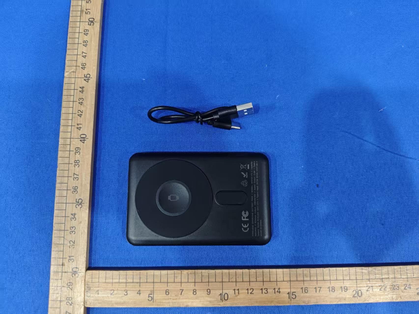
EMOIPCV3A
May 27, 2026Magnetic Wallet Power Bank
Equipment Class
DCD - Part 15 Low Power Transmitter Below 1705 kHz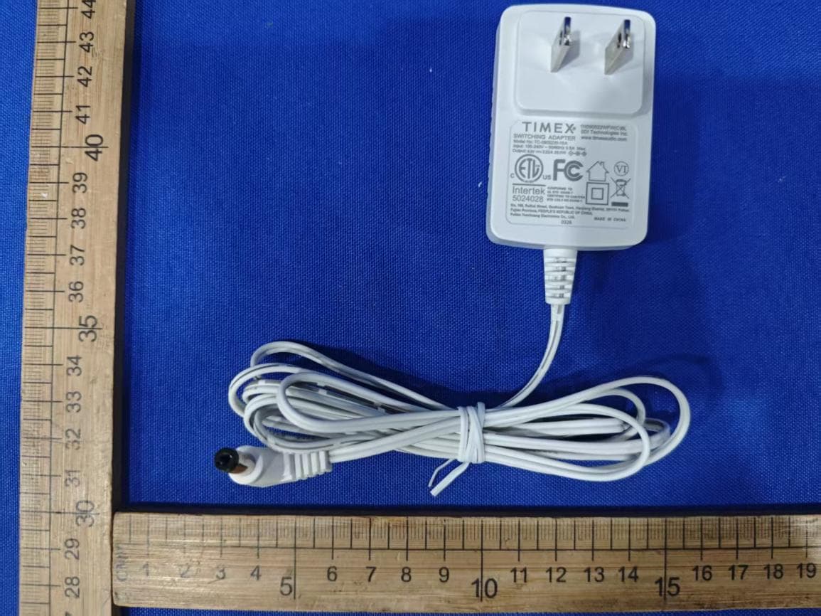
EMOTW502A
Apr 22, 2026ALARM CLOCK WITH NIGHTLIGHT AND FAST WIRELESS CHARGING
Equipment Class
DCD - Part 15 Low Power Transmitter Below 1705 kHz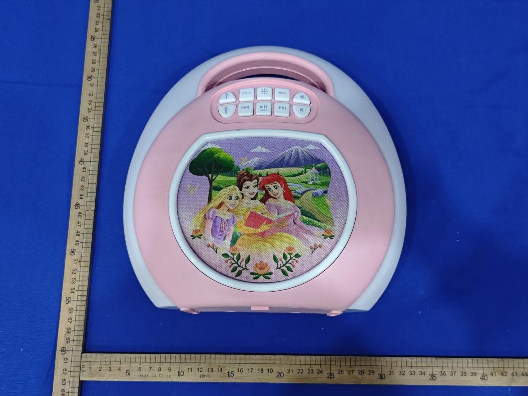
EMO555B
Nov 23, 2025Bluetooth Karaoke
Equipment Class
DSS - Part 15 Spread Spectrum Transmitter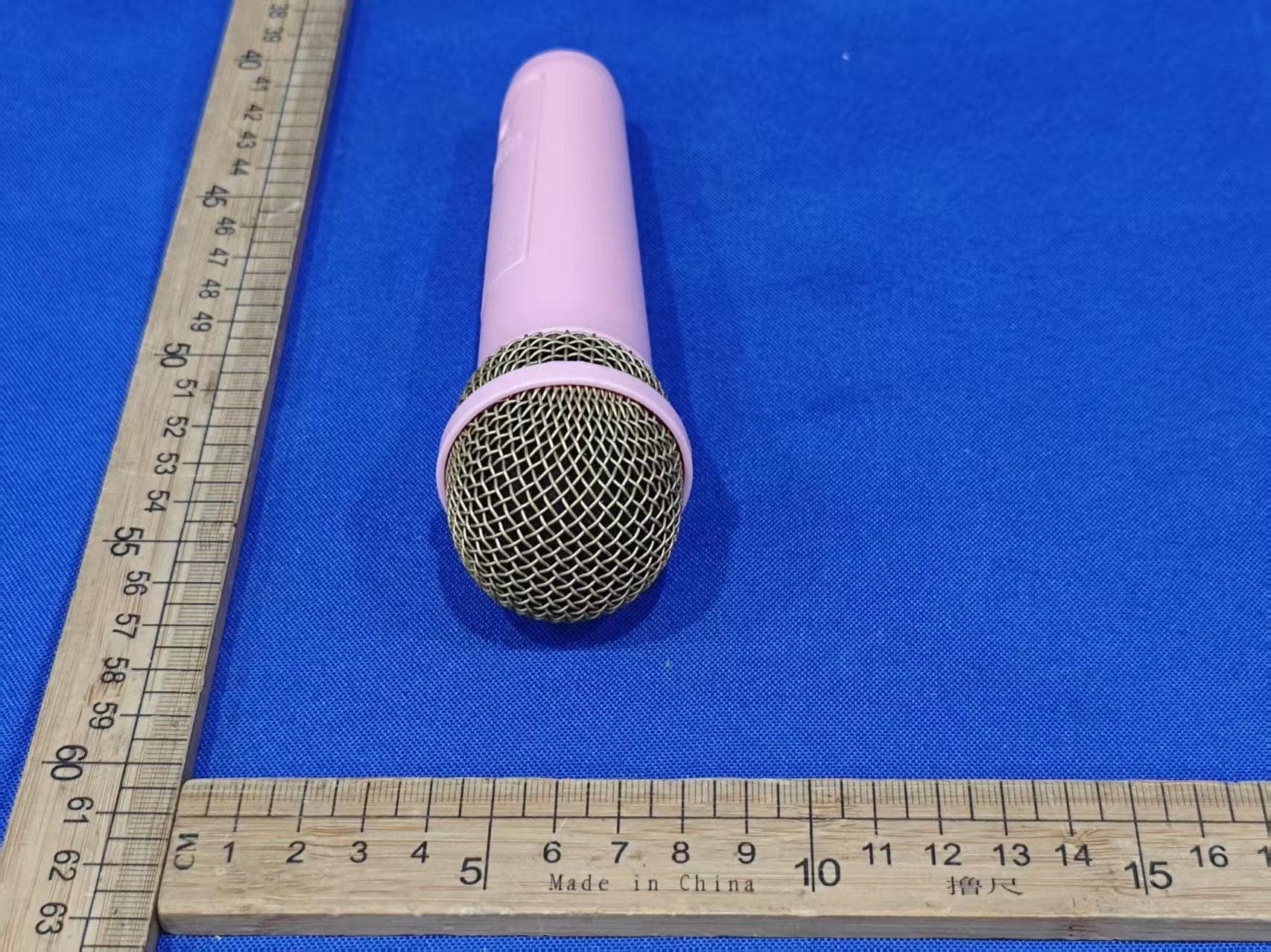
EMO555BM
Nov 23, 2025Bluetooth Karaoke
Equipment Class
DTS - Digital Transmission System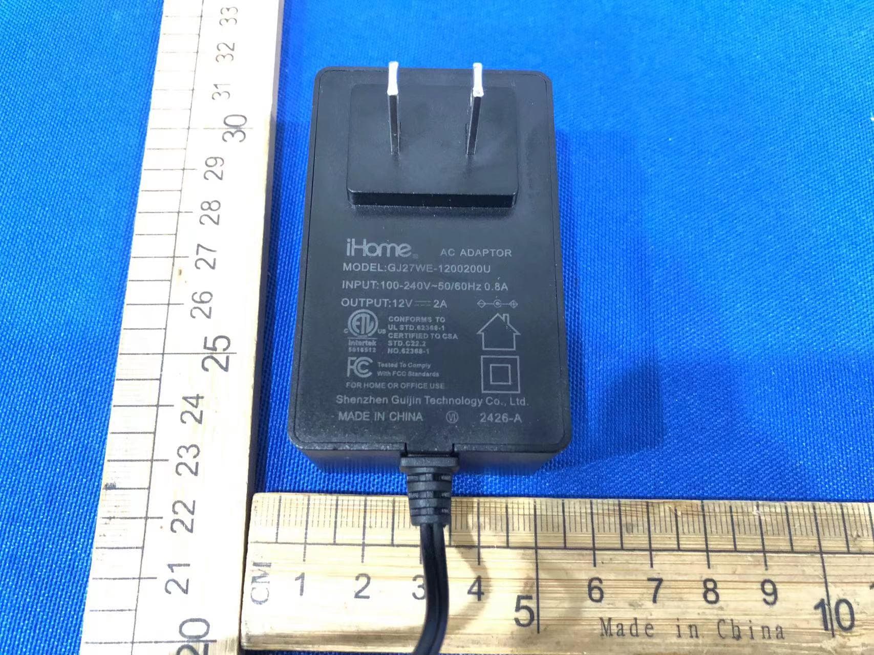
EMOIBTW112A
Sep 07, 2024Bluetooth Alarm Clock with wireless and USB charging
Equipment Class
DSS - Part 15 Spread Spectrum Transmitter