EMOTW500BCompact Bedside Alarm Clock Radio with Wireless Charging with USB Charging
SDI Technologies Inc.Application Details
- Equipment Class
- DCD - Part 15 Low Power Transmitter Below 1705 kHz
- Date of Grant
- Jan 11, 2022
- Application Purpose
- Original Equipment
- Date of Application
- Jan 11, 2022
- Equipment Note
- Compact Bedside Alarm Clock Radio with Wireless Charging with USB Charging
- Frequency Range
- 0.11050000 - 0.20500000
- Company
- SDI Technologies Inc.
- Country
- United States
Documents & Files
Document Text
Text extracted from the exhibit documents filed with the FCC. Open a document above to read the original.
Users Manual
TW500 IB (English version) Size: 399 x 266 mm paper sheet, 133 x 133 mm (fold) Color: Black Mat’l: 85gsm WF paper Mar. 10, 2021 * Front 3 2 Controls Overview Table of Contents What’s in the Box Model: TW500 For additional information, online registration, and exclusive special offers visit our website: This product ships with the following items. Make sure all are present. 1. TW500 Alarm Clock (phone not included) 2. Instruction book 4 Connecting to Power Source Connect the included AC adapter to the DC jack located on the back of the unit and connect the other end to a working wall outlet. Set Up Setting the Time 5 1 Display Backup Battery Your new Timex Clock includes a built-in battery backup system that will maintain the time and alarm settings during a temporary power interruption. Remove the battery pull tab located on the bottom of the unit. When the Low Backup Battery Icon glows on the display, it is time to the replace the backup battery. To silence a sounding alarm and reset it come on the next day at the same time, press and release the Power/Alarm Reset Button. RESETTING AN ALARM TO COME ON THE NEXT DAY DUAL ALARM FM CLOCK RADIO WITH WIRELESS + USB CHARGING 3. Power adapter What’s in the Box.................................................................................................................................. 1 Controls Overview ................................................................................................................................ 2 Display.................................................................................................................................................. 3 Backup Battery ..................................................................................................................................... 3 Product Care ........................................................................................................................................ 3 Set Up .................................................................................................................................................. 4 Setting the Time ................................................................................................................................... 4 Setting and Using Alarms ..................................................................................................................... 5 Sleep Mode .......................................................................................................................................... 6 Wireless Charging ............................................................................................................................. 6-7 Charging Devices via USB Port ........................................................................................................... 7 FM Radio and Presets.......................................................................................................................... 8 Troubleshooting .................................................................................................................................... 8 Safety Information ........................................................................................................................... 9-10 Warranty Information ...........................................................................................................................11 Top Panel ON / OFFDIMMERTIME SETSLEEP ALARM ONEALARM TWOVOLUMESET Battery Backup Compartment DC Jack (5V/3A) USB Charging Port (5V/1A) FM Antenna (extend for best reception) Back Panel WIRELESS CHARGING AREA PLUS Press to increase settings MINUS Press to decrease settings ALARM ONE & TWO VOLUME SETTINGS POWER/ DISPLAY DIMMER Press to Adjust Display Brightness (cycle for 3 brightness levels, including OFF) SNOOZE Press to Snooze Alarm SLEEP When the radio is on, press Sleep repeatedly to select a sleep period: (10-90 minutes or OFF) TIME SET/FM PRESETS Wireless Charging Status PM Indicator Low Backup Battery Alarm 1 (Wake to Buzzer/Radio) Setting and Using Alarms 1 Press and hold Alarm One OR Alarm Two. Each alarm can be set in the same way. 2 3 ALARM ONEALARM TWO OR Press and release the Minus Button (-) as needed to adjust the hour. Press and release the Plus Button (+) as needed to adjust the minute. Press Alarm One or Alarm Two to confirm the alarm time. NOTE: The PM indicator will light on the display when the hour is set for PM. There is no AM indicator. SET SET ALARM ONEALARM TWO OR Press and release the Minus Button (-) or Plus Button (+) to select your wake to source: buzzer or radio. The or icon will light on the display to confirm your selection. Press Alarm One or Alarm Two to confirm settings. ALARM ONEALARM TWO OR SET Press and release the Snooze Button when the alarm sounds to silence it for 9 minutes. Snooze can be used several times during an alarm cycle. SNOOZING THE ALARM ON / OFF 1. Keep unit connected to AC power when replacing the battery, or you will lose settings. 2. Use a Phillips screwdriver to open the battery backup compartment door located on the bottom of the unit. 3. Remove exhausted battery and replace with a fresh CR-2032 battery, making sure the ‘+’ side is facing up. 4. Replace the battery compartment door. Do not overtighten the screw. 3 1 Press and hold the Time Set Button. 2 Press and release the Minus Button (-) repeatedly to adjust the hour. Press and release the Plus Button (+) repeatedly to adjust the minute. NOTE: The PM indicator will light on the display when the hour is set for PM. There is no AM indicator. SET Press the Time Set Button to confirm settings. SET Alarm 2 (Wake to Buzzer/Radio) ALARM RESET/ FM RADIO Product Care • A protective film is attached to the front of the display. It can be removed by peeling it off. • Place the unit on a level surface away from sources of direct sunlight or excessive heat. • Protect your furniture when placing your unit on a …
Text truncated - open the document above for the full version.
Cover Letter(s)
SDI Technologies Inc. ADD: 1299 Main St. Rahway NJ 07065, United States Tel: 732 574-9000 Fax: 732 574-2634 Email: [email protected] Product Similarity Declaration 2021-12-28 FEDERAL COMMUNICATIONS COMMISSIONS Authorization and Evaluation Division 7435 Oakland Mills Road Columbia, MD 21046 To Whom It May Concern, We, SDI Technologies Inc., hereby declare that we have a product named as Compact Bedside Alarm Clock Radio with Wireless Charging with USB Charging (Model number: TW500) (FCC ID:EMOTW500B) was tested by Shenzhen Accurate Technology Co., Ltd., meanwhile, for our marketing purpose, we would like to list series models ( TW500B, TW500BC, TW500X X could be single or multiple digits by any alphabets denote different cabinet color) on reports and certificate, all the models are electrically identical. The only difference are the color and Model name. No other changes are made to them. We confirm that all information above is true, and we’ll be responsible for all the consequences. Please contact me if you have any question. Sincerely Yours, Signature: David Stetin Compliance Officer
Cover Letter(s)
SDI Technologies Inc. ADD: 1299 Main St. Rahway NJ 07065, United States Tel: 732 574-9000 Fax: 732 574-2634 Email: [email protected] FCC Confidential Authorization Date: 2021-12-28 FEDERAL COMMUNICATIONS COMMISSIONS Authorization and Evaluation Division 7435 Oakland Mills Road Columbia, MD 21046 Subject: Confidentiality Request regarding application for certification of FCC ID: EMOTW500B In accordance with Sections 0.457 and 0.459 of the Commission’s Rules, SDI Technologies Inc., hereby requests long-term confidential treatment of information accompanying this application as outlined below: Block Diagram Schematics Operation Description The above materials contain proprietary and confidential information not customarily released to the public. The public disclosure of these materials provides unjustified benefits to its competitors in the market. Sincerely Yours, Signature: David Stetin Compliance Officer
External Photos
Shenzhen Accurate Technology Co., Ltd. Project No.: SZNS211126-61122E-RF External Photos Page 1 of 4 External Photos Shenzhen Accurate Technology Co., Ltd. Project No.: SZNS211126-61122E-RF External Photos Page 2 of 4 Shenzhen Accurate Technology Co., Ltd. Project No.: SZNS211126-61122E-RF External Photos Page 3 of 4 Shenzhen Accurate Technology Co., Ltd. Project No.: SZNS211126-61122E-RF External Photos Page 4 of 4
ID Label/Location Info
Shenzhen Accurate Technology Co., Ltd. Project No.: SZNS211126-61122E-RF LABEL AND LOCATION Page 1 of 1 FCC ID Label FCC ID Label Location Information The label shown shall be permanently affixed at a conspicuous location on the device and be readily visible to the user at the time purchase (Labeling requirements per 2.925)
Internal Photos
Shenzhen Accurate Technology Co., Ltd. Project No.: SZNS211126-61122E-RF Internal Photos Page 1 of 8 Internal photos Shenzhen Accurate Technology Co., Ltd. Project No.: SZNS211126-61122E-RF Internal Photos Page 2 of 8 Shenzhen Accurate Technology Co., Ltd. Project No.: SZNS211126-61122E-RF Internal Photos Page 3 of 8 Shenzhen Accurate Technology Co., Ltd. Project No.: SZNS211126-61122E-RF Internal Photos Page 4 of 8 Shenzhen Accurate Technology Co., Ltd. Project No.: SZNS211126-61122E-RF Internal Photos Page 5 of 8 Shenzhen Accurate Technology Co., Ltd. Project No.: SZNS211126-61122E-RF Internal Photos Page 6 of 8 Shenzhen Accurate Technology Co., Ltd. Project No.: SZNS211126-61122E-RF Internal Photos Page 7 of 8 WPT Coil Adapter Shenzhen Accurate Technology Co., Ltd. Project No.: SZNS211126-61122E-RF Internal Photos Page 8 of 8
RF Exposure Info
Shenzhen Accurate Technology Co., Ltd. Report No.: SZNS211126-61122E-RF-00 Version 43: 2021-11-09 Page 9 of 22 FCC- WPT FCC §1.1310, §2.1091- MAXIMUM PERMISSIBLE EXPOSURE (MPE) Applicable Standard According to subpart §1.1310, systems operating under the provisions of this section shall be operated in a manner that ensures that the public is not exposed to radio frequency energy level in excess of the Commission’s guidelines. Limits for Maximum Permissible Exposure (MPE) (§1.1310, §2.1091) (B) Limits for General Population/Uncontrolled Exposure Frequency Range (MHz) Electric Field Strength (V/m) Magnetic Field Strength (A/m) Power Density (mW/cm 2 ) Averaging Time (minutes) 0.3–1.34 614 1.63 *(100) 30 1.34–30 824/f 2.19/f *(180/f²) 30 30–300 27.5 0.073 0.2 30 300–1500 / / f/1500 30 1500–100,000 / / 1.0 30 f = frequency in MHz; * = Plane-wave equivalent power density; According with KDB 680106 D01 RF Exposure Wireless Charging Apps v03r01 clause 3 c) According to KDB 680106 D01 RF Exposure Wireless Charging App v03r01 clause 5 b) Shenzhen Accurate Technology Co., Ltd. Report No.: SZNS211126-61122E-RF-00 Version 43: 2021-11-09 Page 10 of 22 FCC- WPT Block Diagram of Test Setup Note: 20 cm for Top test. Test Data Environmental Conditions Temperature:26.5 °C Relative Humidity: 52 % ATM Pressure: 101.0 kPa The testing was performed by Ting Lü on 2021-12-24. Test Mode: Wireless Charging (Full load) 15cm Shenzhen Accurate Technology Co., Ltd. Report No.: SZNS211126-61122E-RF-00 Version 43: 2021-11-09 Page 11 of 22 FCC- WPT H-Field Strength Frequency Range (kHz) Position A (A/m) Position B (A/m) Position C (A/m) Position D (A/m) Position E (A/m) 50% Limit (A/m) Limit (A/m) 110.5-205 0.241 0.245 0.242 0.242 0.263 0.815 1.63 E-Field Strength Frequency Range (kHz) Position A (V/m) Position B (V/m) Position C (V/m) Position D (V/m) Position E (V/m) 50% Limit (V/m) Limit (V/m) 110.5-205 0.481 0.464 0.431 0.436 0.452 307 614 Note: Test with 15cm distance from the center of the probe(s) to the edge of the device, 20cm from the center of the probe(s) to the top of the device. Result: Pass Considerations of compliance 680106 D01 RF Exposure Wireless Charging App v03r01 clause 5 b: (1) Power transfer frequency is less than 1 MHz. Yes, the operation frequency is 110.5-205kHz. (2) Output power from each primary coil is less than or equal to 15 watts. Yes, the maximum output power of primary coil is 5Watts. (3) The system may consist of more than one source primary coils, charging one or more clients. If more than one primary coil is present, the coil pairs may be powered on at the same time. The transfer system includes one primary coils to detect and allow coupling only between individual pairs of coils. (4) Client device is placed directly in contact with the transmitter. Yes, client device is placed directly in contact with the transmitter (5) Mobile exposure conditions only (portable exposure conditions are not covered by this exclusion). Yes, mobile exposure conditions only (6) The aggregate H-field strengths anywhere at or beyond 15 cm surrounding the device, and 20 cm away from the surface from all coils that by design can simultaneously transmit, and while those coils are simultaneously energized, are demonstrated to be less than 50% of the applicable MPE limit. Yes, the test result for H and E-Field strength less than 50% of the MPE limit.
Test Report
Note: This report may ★ contain data that are not covered by the A2LA accreditation and are marked with an asterisk “ ”. Shenzhen Accurate Technology Co., Ltd. is not responsible for the authenticity of any test data provided by the applicant. Data included from the applicant that may affect test results are marked with an asterisk ’*’. Customer model name, addresses, names, trademarks etc. are not considered data. This report cannot be reproduced except in full, without prior written approval of the Company. Unless otherwise stated the results shown in this test report refer only to the sample(s) tested. This report is valid only with a valid digital signature. The digital signature may be available only under the Adobe software above version 7.0. Shenzhen Accurate Technology Co., Ltd. 1/F., Building A, Changyuan New Material Port, Science & Industry Park, Nanshan District, Shenzhen, Guangdong, P.R. China Tel: +86 755-26503290 Fax: +86 755-26503396 Web: www.atc-lab.com Version 43: 2021-11-09 Page 1 of 22 FCC- WPT TEST REPORT Applicant Name : SDI Technologies Inc. Address : 1299 Main St. Rahway NJ 07065, United States Report Number : SZNS211126-61122E-RF-00 FCC ID: EMOTW500B Test Standard (s) FCC Part 15C Sample Description Product Type: Compact Bedside Alarm Clock Radio with Wireless Charging with USB Charging Model No.: TW500 Multiple Model(s) No.: TW500B, TW500BC, TW500X (X could be single or multiple digits by any alphabets denote different cabinet color) (Please refer to DOS for Model difference) Trade Mark: Timex Date Received: 2021/11/26 Date of Test: 2021/12/08~2021/12/24 Report Date: 2021/12/28 Test Result: Pass* * In the configuration tested, the EUT complied with the standards above. Prepared and Checked By: Approved By: Ting Lü Robert Li EMC Engineer EMC Engineer Shenzhen Accurate Technology Co., Ltd. Report No.: SZNS211126-61122E-RF-00 Version 43: 2021-11-09 Page 2 of 22 FCC- WPT TABLE OF CONTENTS GENERAL INFORMATION ....................................................................................................................................... 3 PRODUCT DESCRIPTION FOR EQUIPMENT UNDER TEST (EUT) ..................................................................................... 3 OBJECTIVE ................................................................................................................................................................... 3 TEST METHODOLOGY .................................................................................................................................................. 3 MEASUREMENT UNCERTAINTY .................................................................................................................................... 3 TEST FACILITY ............................................................................................................................................................. 4 SYSTEM TEST CONFIGURATION .......................................................................................................................... 5 JUSTIFICATION ............................................................................................................................................................. 5 EUT EXERCISE SOFTWARE .......................................................................................................................................... 5 LOCAL SUPPORT EQUIPMENT ....................................................................................................................................... 5 EXTERNAL I/O CABLE .................................................................................................................................................. 5 BLOCK DIAGRAM OF TEST SETUP ................................................................................................................................ 6 SUMMARY OF TEST RESULTS ............................................................................................................................... 7 TEST EQUIPMENT LIST ........................................................................................................................................... 8 FCC §1.1310, §2.1091- MAXIMUM PERMISSIBLE EXPOSURE (MPE) ............................................................. 9 APPLICABLE STANDARD .............................................................................................................................................. 9 BLOCK DIAGRAM OF TEST SETUP .............................................................................................................................. 10 TEST DATA ................................................................................................................................................................ 10 FCC§15.203 – ANTENNA REQUIREMENT ........................................................................................................... 12 APPLICABLE STANDARD ............................................................................................................................................ 12 ANTENNA CONNECTED CONSTRUCTION .................................................................................................................... 12 FCC §15.207 – AC LINE CONDUCTED EMISSION ............................................................................................. 13 APPLICABLE STANDARD ............................................................................................................................................ 13 EUT SETUP ................................................................................................................................................................ 13 EMI TEST RECEIVER SETUP ....................................................................................................................................... 13 TEST PROCEDURE ............................................................…
Text truncated - open the document above for the full version.
Test Setup Photos
Shenzhen Accurate Technology Co., Ltd. Project No.: SZNS211126-61122E-RF Page 1 of 7 Photo of Conducted Emission Measurement Shenzhen Accurate Technology Co., Ltd. Project No.: SZNS211126-61122E-RF Page 2 of 7 Photo of Radiated Emission Measurement (Below 30MHz) Photo of Radiated Emission Measurement (Below 1GHz) Shenzhen Accurate Technology Co., Ltd. Project No.: SZNS211126-61122E-RF Page 3 of 7 Photo of E-Field Strength Position A (Distance 15cm) Position B (Distance 15cm) Shenzhen Accurate Technology Co., Ltd. Project No.: SZNS211126-61122E-RF Page 4 of 7 Position C (Distance 15cm) Position D (Distance 15cm) Shenzhen Accurate Technology Co., Ltd. Project No.: SZNS211126-61122E-RF Page 5 of 7 Position E (Distance 20cm) Photo of H-Field Strength Position A (Distance 15cm) Shenzhen Accurate Technology Co., Ltd. Project No.: SZNS211126-61122E-RF Page 6 of 7 Position B (Distance 15cm) Position C (Distance 15cm) Shenzhen Accurate Technology Co., Ltd. Project No.: SZNS211126-61122E-RF Page 7 of 7 Position D (Distance 15cm) Position E (Distance 20cm)
Contact Information
Applicant
David Stetin(Compliance Officer)
Test Firm
Shenzhen Accurate Technology Co., Ltd.Lisa Zhang
[email protected]+86-755-26503290
Technical Specifications
| # | Rule Parts | Frequency Range | Power Output |
|---|---|---|---|
| 1 | 15C | 0.1105 MHz - 0.205 MHz | - |
Other Applications from SDI Technologies Inc.
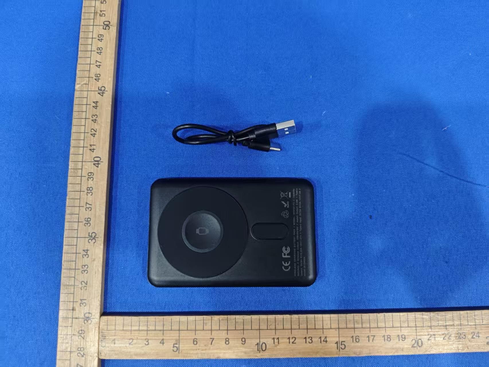
EMOIPCV3A
May 27, 2026Magnetic Wallet Power Bank
Equipment Class
DCD - Part 15 Low Power Transmitter Below 1705 kHz
EMOTW502A
Apr 22, 2026ALARM CLOCK WITH NIGHTLIGHT AND FAST WIRELESS CHARGING
Equipment Class
DCD - Part 15 Low Power Transmitter Below 1705 kHz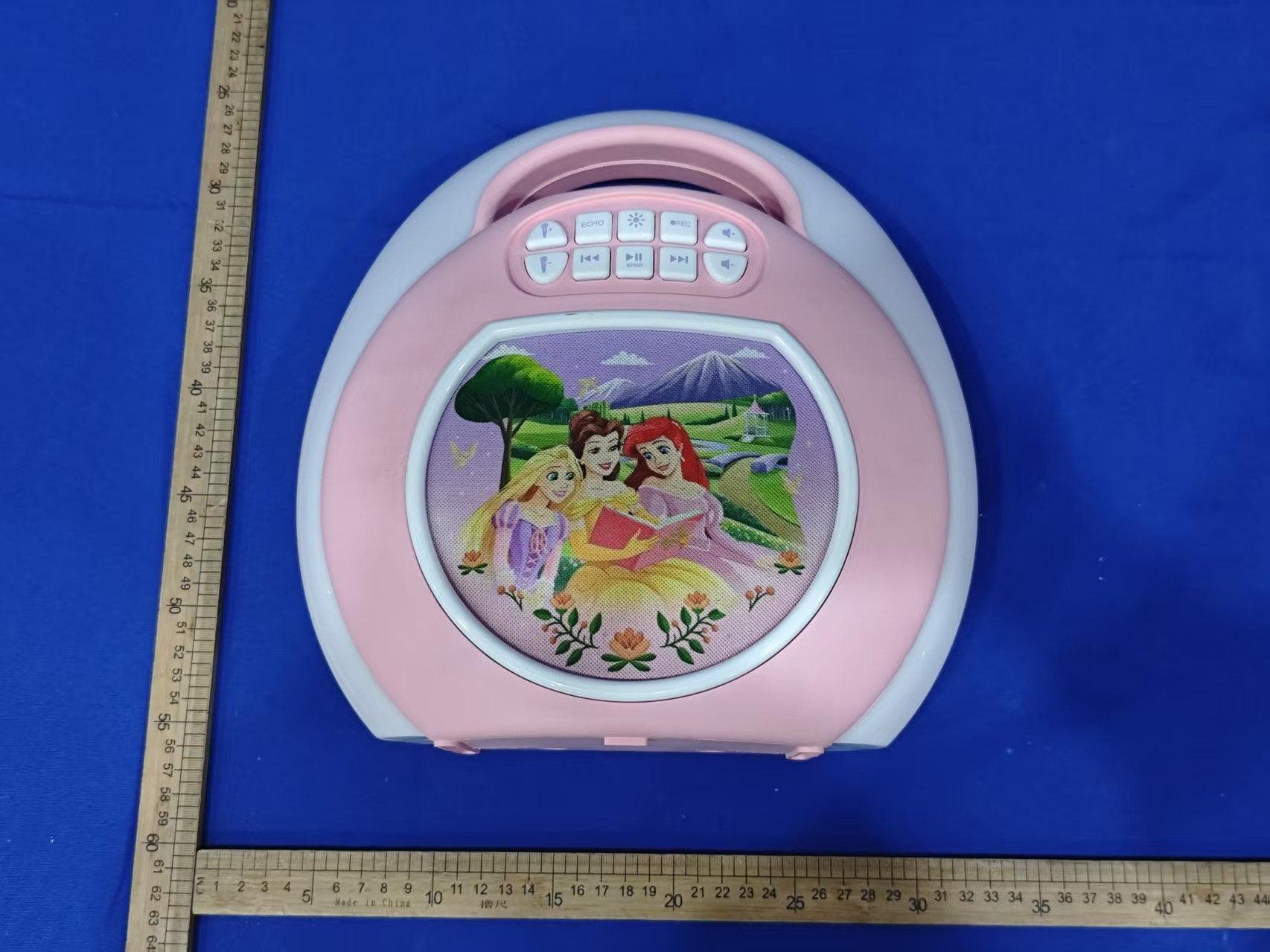
EMO555B
Nov 23, 2025Bluetooth Karaoke
Equipment Class
DSS - Part 15 Spread Spectrum Transmitter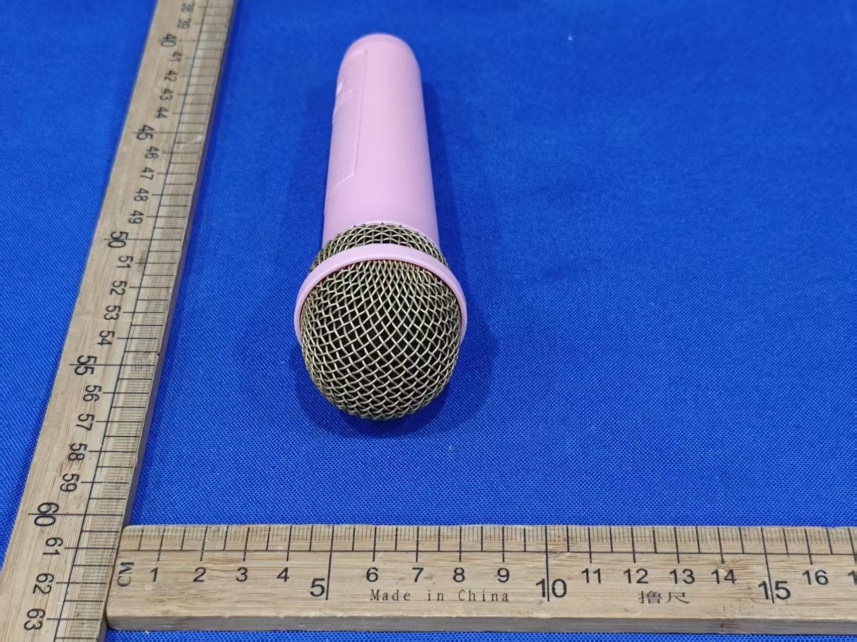
EMO555BM
Nov 23, 2025Bluetooth Karaoke
Equipment Class
DTS - Digital Transmission System
EMOIBTW112A
Sep 07, 2024Bluetooth Alarm Clock with wireless and USB charging
Equipment Class
DSS - Part 15 Spread Spectrum Transmitter