ESX4000438Home Bluetooth Speaker
Guangzhou Panyu Juda Car Audio Equipment Co.,Ltd.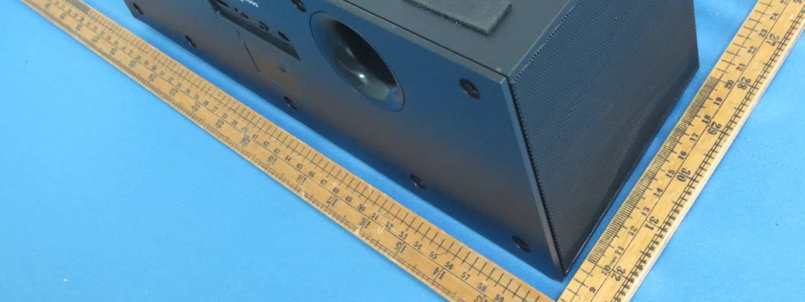
Click to zoom
Application Details
- Equipment Class
- DXX - Part 15 Low Power Communication Device Transmitter
- Date of Grant
- Apr 07, 2013
- Application Purpose
- Original Equipment
- Date of Application
- Apr 07, 2013
- Equipment Note
- Home Bluetooth Speaker
- Frequency Range
- 2402.00000000 - 2480.00000000
- Country
- China
Documents & Files
Document Text
Text extracted from the exhibit documents filed with the FCC. Open a document above to read the original.
Users Manual
THE P ERFORMANCE YOU NEED ® ® Home Bluetooth ® Speaker User’s Guide 4000438 Please read this user’s guide before using your new speaker. 2 2 3 3 4 4 5 5 Connect Power Connect your speaker to the standard wall outlet using the AC power adapter and AC cable. The standby indicator lights red. 1. Plug the output cable end of the AC power adapter into the speaker’s DC IN jack. 2. Plug the AC cable to the jack of the AC power adapter. 3. Plug the AC cable to the wall outlet. The power indicator of the AC power adapter lights. Use Your Speaker 1. Press the power button (G), the Bluetooth indicator flashes red and blue as the speaker searches for a Bluetooth-enabled device. 2. Activate your device’s Bluetooth function (refer to your device’s user’s guide). 3. When AUVIO4000438 appears in the Bluetooth devices list, pair it to your device. 4. You can control your speaker through your device or the remote or with the speaker’s buttons. Package Contents Home Bluetooth Speaker AC Power Adapter AC Cable Remote Control User’s Guide Features Sonic emotion absolute 3D technology* adopted to produce rich, full sound that permeates every inch of your room Remote for conveniently controlling the speaker from a distance USB charging port charges your devices Compatible with most Bluetooth enabled tablets, laptops, MP3 players, and smartphones with iOS or Android™ platforms * Sonic Emotion Absolute 3D is the listening experience. n Note: You can download the free Auvio EQ App from the App Store SM and Google Play TM to customize your calls and music. device but resumes connection once the device is close. If the speaker malfunctions, reset it by pressing §/ twice when the Bluetooth indicator flashes red and blue. Charge Your Device 1. Set the A/B switch for charging your device: A for Apple, B for Samsung. 2. Use a USB cable (not included) to connect your device to the speaker’s USB port. Use AUX IN For audio devices without Bluetooth function, use an audio cable (not included) to connect it to your speaker’s AUX IN jack. The Bluetooth indicator lights red and then turns off. Volume +/– Previous/Next Power On/Off Play/Pause/ Disconnect Bluetooth Sonic Emotion 3D Indicator 5 / Version 1.2 Brand / Confidential sonic emotion ag 2012 Logo Standard version 5 / Version 1.2 Brand / Confidential sonic emotion ag 2012 Logo Standard version n Note: Press and hold § for 4 seconds to disconnect Bluetooth. The speaker starts searching for other Bluetooth devices. If your device uses Android 2.0 and below, enter the password 0000 for Bluetooth connection. If the connected device moves too far away from the speaker, the speaker disconnects from the A/B Switch AUX IN USB Port Bluetooth Indicator Fully insert AC cable Power Indicator Standby Indicator 4000438_UG_EN_022513.indd 1-53/6/2013 10:42:51 AM 6 6 7 7 8 8 9 9 10 10 Printed in China 03A13 4000437 © 2013. Ignition L.P. All rights reserved. Auvio is a registered trademark used by Ignition L.P. Package and user documentation are recyclable. User documentation contains recycled material. The Bluetooth ® word mark and logos are registered trademarks owned by Bluetooth SIG, Inc. and any use of such marks by Ignition L.P. is under license. Other trademarks and trade names are those of their respective owners. Sonic Emotion and 5 / Version 1.2 Brand / Confidential sonic emotion ag 2012 Logo Standard version are registered trademarks of sonic emotion ag. Google Play and Android are trademarks of Google Inc. Apple is a trademark of Apple Inc., registered in the United States and other countries. Samsung is a registered trademark of Samsung Electronics Co., Ltd. IGNITION L.P. EXPRESSLY DISCLAIMS ALL WARRANTIES AND CONDITIONS NOT STATED IN THIS LIMITED WARRANTY. ANY IMPLIED WARRANTIES THAT MAY BE IMPOSED BY LAW, INCLUDING THE IMPLIED WARRANTY OF MERCHANTABILITY AND, IF APPLICABLE, THE IMPLIED WARRANTY OF FITNESS FOR A PARTICULAR PURPOSE, SHALL EXPIRE ON THE EXPIRATION OF THE STATED WARRANTY PERIOD. EXCEPT AS DESCRIBED ABOVE, IGNITION L.P. SHALL HAVE NO LIABILITY OR RESPONSIBILITY TO THE PURCHASER OF THE PRODUCT OR ANY OTHER PERSON OR ENTITY WITH RESPECT TO ANY LIABILITY, LOSS OR DAMAGE CAUSED DIRECTLY OR INDIRECTLY BY USE OR PERFORMANCE OF THE PRODUCT OR ARISING OUT OF ANY BREACH OF THIS WARRANTY, INCLUDING, BUT NOT LIMITED TO, ANY DAMAGES RESULTING FROM INCONVENIENCE AND ANY LOSS OF TIME, DATA, PROPERTY, REVENUE, OR PROFIT AND ANY INDIRECT, SPECIAL, INCIDENTAL, OR CONSEQUENTIAL DAMAGES, EVEN IF IGNITION L.P. HAS BEEN ADVISED OF THE POSSIBILITY OF SUCH DAMAGES. Some states do not allow limitations on how long an implied warranty lasts or the exclusion or limitation of incidental or consequential damages, so the above limitations or exclusions may not apply to you. This warranty gives you specific legal rights, and you may also have other rights which vary from state to state. You may contact Ignition L.P. at: Ignition L.P., 3102 Maple Ave., Suite 450, Dallas, TX 75201 02/09 For product support, call 1-866-315-0426 This device complies with Part 15 of the FCC Rules. Operation is subject to the following two conditions: (1) This device may not cause harmful interference, and (2) this device must accept any interference received, including interference that may cause undesired operation. Limited Warranty Ignition L.P. warrants this product against defects in materials and workmanship under normal use by the original purchaser for ninety (90) days after the date of purchase. IGNITION L.P. MAKES NO OTHER EXPRESS WARRANTIES. This warranty does not cover: (a) damage or failure caused by or attributable to abuse, misuse, failure to follow instructions, improper installation or maintenance, alteration, accident, Acts of God (such as floods or lightning), or excess voltage or current; (b) improper or incorrectly performed repairs by persons who are not a Ignition L.P. Authorized Service Facility; (c) consumables such as fuses or batteries; (d) ordinary wear and tear or co…
Text truncated - open the document above for the full version.
Block Diagram
ANT 2402-2480MHz U14 U27 U9 U15 U12 U7 U6 U2 U29 U10 DC to DC U8 U3 RF 2.4 GHZ Radio I/O ROM RAM MCU Kalimba DSP XTAL CSR BC57F687A05 Balun Filter Fil I2c EEPROM PIO Audio In/Output 16MHz AN T 2402-2480MHz
External Photos
External photos
ID Label/Location Info
AUVIO 4000438 BL2608 0.1mm PVC (REACH ROHS) AUVIO 4000438 4.12.4.L2608011RR 24.8 mm 40.2 mm
Internal Photos
Internal photos
Operational Description
Technical Description The equipment under test (EUT) is a Home Bluetooth Speaker. The EUT can be powered by AC/DC adapter (Input 100-240, 50/60Hz, 1.5A max; Output: 15Vdc, 4A). For more detail information pls. refer to the user manual. Channel List 2402 2403 2404 2405 2406 2407 2408 2409 2410 2411 2412 2413 2414 2415 2416 2417 2418 2419 2420 2421 2422 2423 2424 2425 2426 2427 2428 2429 2430 2431 2432 2433 2434 2435 2436 2437 2438 2439 2440 2441 2442 2443 2444 2445 2446 2447 2448 2449 2450 2451 2452 2453 2454 2455 2456 2457 2458 2459 2460 2461 2462 2463 2464 2465 2466 2467 2468 2469 2470 2471 2472 2473 2474 2475 2476 2477 2478 2479 2480 Modulation Type: GFSK, ∏ ∏∏ ∏/4DQPSK, 8DPSK Bluetooth Version: 2.1 with EDR function without AFH mode Antenna Type: Integral antenna Antenna Gain: 0dBi The nominal radiated output power (e.i.r.p) specified: 0dBm ( Tolerance: +/- 3dB) The nominal conducted output power specified: 0dBm ( Tolerance: +/- 3dB) The function of main IC is mentioned as below. 1) U14 acts as Bluetooth Module. 2) U9 , U15 acts as power regulator(DIGITAL AMPLIFIER POWER STAGE). 3) U27 acts as a MCU 4) U2 acts as 3D PROCESSOR IC 5) U3 acts as Flash IC 6) U6 acts as AEE and ADC IC 7) U8 acts as EEPROM IC 8) U10 acts as DC to DC IC 9) U12 acts as USB CHARGING IC 10) U7 acts as CHANNEL SELECTOR IC 11) U29 acts as Oscillator IC In Bluetooth Module: 1) U1 acts as Bluetooth Chip. 2) Y1 is a 16MHz oscillator for Bluetooth Chip . 3) U3 acts as EEPROM. 4) T1 is a filter
RF Exposure Info
1 INTERTEK TESTING SERVICES RF Exposure report The equipment under test (EUT) is a Home Bluetooth Speaker. The EUT can be powered by AC/DC adapter (Input 100-240, 50/60Hz, 1.5A max; Output: 15Vdc, 4A). For more detail information pls. refer to the user manual. Modulation Type: GFSK, ∏/4DQPSK, 8DPSK Bluetooth Version: 2.1 with EDR function and without AFH mode Antenna Type: Integral antenna Antenna Gain: 0dBi The nominal radiated output power (e.i.r.p) specified: 0dBm ( Tolerance: +/- 3dB) The worst-case radiated emission for the EUT is 95.4dBμV/m at 3m in the frequency 2.480GHz = [(FS*D) ^2 / 30] mW = 0.1 7 dBm which is within the production variation. According to FCC Part 2.1091, this unlicensed transmitting devices is categorically excluded from routine environmental evaluation for RF exposure prior to equipment authorization or use, According to the KDB 447498 and OET 65, the simple calculation as below: For Maximum Permissible Exposure (MPE) evaluation of the product, the maximum power density at 20 cm from this transmitter shall be less than the General Population / Uncontrolled MPE limit in OET Bulletin 65. The maximum radiated output power = 3 dBm = 2.0mW The source-based time averaged maximum radiated power (including the tune-up tolerance) = 2.0 * Duty Cycle = 1.7 mW From above data, the exposed power density at a distance (R) of 20cm from the center of radiation of the antenna can be calculated according to OET Bulletin 65 as follow: = 1.7 mW / 4πR^2 = 0.0003 mW/cm^2 The MPE limit is 1.0 mWcm-2 for general population and uncontrolled exposure in the Bluetooth frequency range according to FCC Part 1.1310. As the measured power density at 20cm from the transmitter is lower than the MPE limit, the compliance to the MPE limit can be ensured by indicating the minimum 20cm separation between the transmitter's radiating structure and body of the user or nearby persons. Transmitter Duty Cycle Calculation 2 Based on the Bluetooth Specification (BT version: 2.1 + EDR function, without AFH), transmitter duty cycle is dependent of packet type (DH1, DH3 and DH5). For one period for a pseudo-random hopping through all 79 RF channels, for DH5: One hopset consists of 5 TX slot and 1 RX slot. Duty cycle = 5 / 6 = 0.833 The following RF exposure statement is proposed to be included in the user manual: “FCC RF Radiation Exposure Statement Caution: This Transmitter must be installed to provide a separation distance of at least 20 cm from all persons.”
Schematics
U27 U29 U14 ANT 2402-2480MHz U7 U6 U8 U2 U9 U15 U12 U3 U10
Test Report
• The test results reported in this test report shall refer only to the sample actually tested and shall not refer or be deemed to refer to bulk from which such a sample may be said to have been obtained. • This report is for the exclusive use of Intertek's Client and is provided pursuant to the agreement between Intertek and its Client. Intertek's responsibility and liability are limited to the terms and conditions of the agreement. Intertek assumes no liability to any party, other than to the Client in accordance with the agreement, for any loss, expense or damage occasioned by the use of this report. Only the Client is authorized to copy or distribute this report. Any use of the Intertek name or one of its marks for the sale or advertisement of the tested material, product or service must first be approved in writing by Intertek. The observations and test results referenced from this report are relevant only to the sample tested. This report by itself does not imply that the material, product, or service is or has ever been under an Intertek certification program. • For Terms And Conditions of the services, it can be provided upon request. • The evaluation data of the report will be kept for 3 years from the date of issuance. TRF No.: FCC 15C_TX_b Intertek Testing Services Shenzhen Ltd. Kejiyuan Branch 6F, D Block, Huahan Building, Langshan Road, Nanshan District, Shenzhen, P. R. China Tel: (86 755) 8601 6288 Fax: (86 755) 8601 6751 Website: www.china.intertek-etlsemko.com Guangzhou Panyu Juda Car Audio Equipment Co., Ltd. Application For Certification FCC ID: ESX4000438 Home Bluetooth Speaker Model: 4000438 2.4GHz Transceiver Report No.: 130125006SZN -001 We hereby certify that the sample of the above item is considered to comply with the requirements of FCC Part 15, Subpart C for Intentional Radiator, mention 47 CFR [10-1-12] Prepared and Checked by: Approved b y: Sign on file William Chen Engineer Billy Li Supervisor Date: 20 March 2013 INTERTEK TESTING SERVICES TRF No.: FCC 15C_TX_b FCC ID: ESX4000438 i LIST OF EXHIBITS INTRODUCTION EXHIBIT 1: General Description EXHIBIT 2: System Test Configuration EXHIBIT 3: Emission Results EXHIBIT 4: Equipment Photographs EXHIBIT 5: Product Labelling EXHIBIT 6: Technical Specifications EXHIBIT 7: Instruction Manual EXHIBIT 8: Miscellaneous Information EXHIBIT 9: Test Equipment List INTERTEK TESTING SERVICES TRF No.: FCC 15C_TX_b FCC ID: ESX4000438 ii MEASUREMENT/TECHNICAL REPORT Guangzhou Panyu Juda Car Audio Equipment Co., Ltd. - MODEL: 4000438 FCC ID: ESX4000438 This report concerns (check one:) Original Grant X Class II Change Equipment Type: DXX - Part 15 Low Power Communication Device Transmitter Deferred grant requested per 47 CFR 0.457(d)(1)(ii)? Yes No X If yes, defer until: date Company Name agrees to notify the Commission by: date of the intended date of announcement of the product so that the grant can be issued on that date. Transition Rules Request per 15.37? Yes No X If no, assumed Part 15, Subpart C for intentional radiator − the new 47 CFR [10-1-12 Edition] provision. Report prepared by: Billy Li Intertek Testing Services Shenzhen Ltd. Kejiyuan Branch 6F, Block D, Huahan Building, Langshan Road, Nanshan District, Shenzhen, P. R. China Phone: (86 755) 8614 0645 Fax: (86 755) 8601 6751 INTERTEK TESTING SERVICES TRF No.: FCC 15C_TX_b FCC ID: ESX4000438 iii Table of Contents 1.0 General Description ............................................................................................ 2 1.1 Product Description ............................................................................................ 2 1.2 Related Submittal(s) Grants ............................................................................... 2 1.3 Test Methodology ............................................................................................... 2 1.4 Test Facility ........................................................................................................ 2 2.0 System Test Configuration ................................................................................. 4 2.1 Justification ........................................................................................................ 4 2.2 EUT Exercising Software .................................................................................... 4 2.3 Special Accessories ........................................................................................... 4 2.4 Equipment Modification ...................................................................................... 4 2.5 Measurement Uncertainty .................................................................................. 5 2.6 Support Equipment List and Description ............................................................. 5 3.0 Emission Results ................................................................................................ 7 3.1Radiated Test Results............................................................................ 8 3.1.1 Field Strength Calculation ................................................................................ 8 3.1.2 Radiated Emission Configuration Photograph .................................................. 9 3.1.3 Radiated Emissions ......................................................................................... 9 3.1.4 Transmitter Spurious Emissions (Radiated)............................................ 11 3.2 Conducted Emission at Mains Terminal................................................... 15 3.2.1 Conducted Emissions Configuration Photograph......................................15 3.2.2 Conducted Emissions........................................................................15 4.0 Equipment Photographs ................................................................................... 19 5.0 Product Labelling .............................................................................................. 21 6.0 Technical Specifications ..…
Text truncated - open the document above for the full version.
Contact Information
Applicant
Xiaofei Liao
Technical Contact
Intertek Testing Services Shenzhen Ltd. Kejiyuan BShawn Xing
[email protected](86-755)86140603
6F, D Block, Huahan Building, Langshan Road · Shenzhen · China
Non-Technical Contact
Intertek Testing Services Shenzhen Ltd. Kejiyuan BShawn Xing
[email protected](86-755)86140603
Test Firm
Intertek Testing Services Shenzhen Ltd.Shawn Xing
Technical Specifications
| # | Rule Parts | Frequency Range | Power Output |
|---|---|---|---|
| 1 | 15C | 2.40 GHz - 2.48 GHz | - |
Other Applications from Guangzhou Panyu Juda Car Audio Equipment Co.,Ltd.
ESX-BMAX30
Apr 30, 2026WIRELESS SPEAKER SYSTEM
Equipment Class
DSS - Part 15 Spread Spectrum TransmitterESX-BMAX5
Jul 23, 2024WIRELESS SPEAKER SYSTEM
Equipment Class
DSS - Part 15 Spread Spectrum TransmitterESX-BMAX10
Jul 22, 2024WIRELESS SPEAKER SYSTEM
Equipment Class
DSS - Part 15 Spread Spectrum Transmitter
ESX-TMAX45
Jul 15, 2023WIRELESS SPEAKER SYSTEM
Equipment Class
DSS - Part 15 Spread Spectrum Transmitter
ESXHP100
Aug 03, 2022Party Speaker
Equipment Class
DSS - Part 15 Spread Spectrum Transmitter