EW780-1740-01Video Monitor
VTech Telecommunications Ltd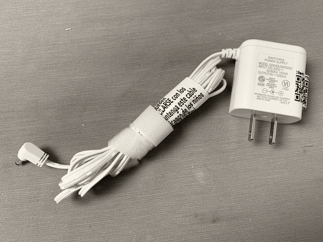
Click to zoom
Application Details
- Equipment Class
- DSS - Part 15 Spread Spectrum Transmitter
- Date of Grant
- Jan 20, 2020
- Application Purpose
- Original Equipment
- Date of Application
- Jan 20, 2020
- Equipment Note
- Video Monitor
- Frequency Range
- 2405.00000000 - 2475.00000000
- Company
- VTech Telecommunications Ltd
- Country
- Hong Kong
Documents & Files
Document Text
Text extracted from the exhibit documents filed with the FCC. Open a document above to read the original.
Users Manual
Note • This baby monitor is intended as an aid. It is not a substitute for proper adult supervision, and should not be used as such. Test your baby monitor You may test the baby monitor before initial use, and at regular times thereafter. Caution • For hearing protection, make sure the parent unit is more than 3 feet (1 meter) away from both baby units. If you hear any high-pitched noise, move the parent unit further until the noise stops. You can also press VOL- on the parent unit to reduce or mute the noise. 1. Make sure your baby unit and parent unit are on. 2. The parent unit displays images from the baby unit. • Speak towards the microphone of the baby unit. You will hear the sound at the parent unit. 3. If you have two baby units, press on your parent unit. The screen switches to the other baby unit. Then, repeat step 2. Power on or off the baby unit • Slide the ON/OFF switch to ON to turn on the baby unit. The POWER LED light turns on. • Slide the ON/OFF switch to OFF to turn off the baby unit. The POWER LED light turns off. Power on or off the parent unit • Press and hold to turn on the parent unit. The screen turns on. • Press and hold again to turn off the parent unit. The screen turns off. Turn on or off the parent unit screen You can turn on or off the parent unit screen without powering off the parent unit. You can still hear sound from the baby units. • Press and hold LCD ON/OFF on the parent unit to turn off the screen. • Press any key on the parent unit to turn on the screen again. Adjust speaker volume To adjust parent unit speaker volume: • Press VOL-/VOL+ on the parent unit to adjust the speaker volume. Note • When the parent unit speaker volume is set to zero, the appears on the screen and the light turns on. To adjust baby unit speaker volume: The baby unit speaker volume determines the lullaby volume and talkback volume transmitted from parent unit. • Press +/VOLUME/- on the baby unit to adjust the speaker volume. To adjust baby unit speaker volume using parent unit: The baby unit speaker volume can also be adjusted in the parent unit. 1. Press MENU when the parent unit is idle. 2. Press or to choose , then press SELECT or . 3. Press to choose . 4. Press or to choose the volume level of the baby unit. 5. Press SELECT to confirm your selection. Adjust LCD brightness You can change the brightness of the parent unit screen from Level 1 to Level 5. The LCD brightness is preset to Level 3. 1. Press MENU when the parent unit is idle. 2. Press or to choose , then press SELECT or . 3. Press or to choose the desired level of brightness, then press SELECT. User’s manual VM3253 VM3253-2 Video Monitor Go to www.vtechphones.com to register your product for enhanced warranty support and the latest VTech product news. Congratulations on purchasing your new VTech product. Before using this product, please read Important safety instructions. This manual has all the feature operations and troubleshooting necessary to install and operate your new VTech product. Please review this manual thoroughly to ensure proper installation and operation of this innovative and feature-rich VTech product. For support, shopping, and everything new at VTech, visit our website at www.vtechphones.com. 1 set for VM3253 2 sets for VM3253-2 To enter Patrol mode: 1. Press MENU when the parent unit is idle. 2. Press or to choose , then press SELECT or . 3. Press or to switch , then press SELECT to confirm your selection. Adjust the sound sensitivity of the baby unit You can choose to hear sounds from the baby unit all the time, or to hear sounds that exceed a certain level. You can use the parent unit to adjust the microphone sensitivity of your baby unit. The higher the sensitivity level, the more sensitive the baby unit is in detecting sounds for transmitting to the parent unit. The VOX sensitivity level is preset to the highest level. VOX Sensitivity level Highest High Medium Low Lowest Description The parent unit speaker is constantly on, and you will hear all sounds (including background noises) from your baby’s room. The parent unit speaker turns on for soft babbling and louder sounds from your baby. It remains quiet when your baby sleeps soundly. The parent unit speaker turns on for loud babbling and louder sounds from your baby. It remains quiet when your baby makes soft sounds. The parent unit speaker turns on for crying and louder sounds from your baby. It remains quiet when your baby makes soft sounds. The parent unit speaker turns on for loud crying or screeching sounds from your baby. It remains quiet when your baby makes soft sounds. 1. Press MENU when the parent unit is idle. 2. Press or to choose , then press SELECT or . 3. Press or to choose the desired sensitivity level, then press SELECT to confirm your selection. NOTESNOTE Note • As long as the Sound-activated Screen setting is on, the screen will turn on automatically when VOX sensitivity is triggered, despite it was off earlier. Tips • You can adjust the baby unit placement to improve the sound detection. • If you want to use a sound machine or white noise machine for natural white noise while using this baby monitor to check on your baby, you can: - Lower the volume of your sound machine or white noise machine; or - Lower the sensitivity level of your baby monitor to medium or below. Default level is the highest level. Turn on or off the sound activation When sound activation is on, as long as no sound is detected within 50 seconds, the parent unit screen will turn off automatically to save power. When your baby unit detects a sound, which exceeds the selected sensitivity level, the sound activation triggers the parent unit screen to turn on automatically. When no sound is detected within 50 seconds, the screen will be off again. 1. Press MENU when the parent unit is idle. 2. Press or to choose , then press SELECT or . 3. Press or to choose or , then press SELECT to confirm your selection. Note • If the sound sensitivity is set to the …
Text truncated - open the document above for the full version.
Cover Letter(s)
To: Federal Communications Commission Office of Engineering and Technology Laboratory Division 7435 Oakland Mills Rd. Columbia MD 21046 From: VTech Telecommunications Ltd 23/F Tai Ping Ind Center Block 1 57 Ting Kok Rd Tai Po NT Hong Kong Regarding: Confidentiality Request regarding application for FCC ID: EW780-1740-01 LONG TERM CONFIDENTIALITY Pursuant to 47 CFR Section 0.459 and 0.457 of the commission’s rules, the applicant hereby request confidential treatment of the documents listed below, associated with the certification application referenced above. Schematic(s) Block Diagrams Operational Descriptions The documents above contain proprietary information not released to the public. Public disclosure of this information may prove harmful to the business of the applicant. SHORT TERM CONFIDENTIALITY Additionally, the applicant requests the following documents be held confidential until the device is marketed or 90 days from the grant date, whichever is less. If the device is marketed within aforementioned days of the Grant Date, the applicant will notify the TCB per FCC KDB 726920 D01 Confidentiality Request Procedures. External Photos Internal Photos Test Setup Photos User manual(s) Sincerely, Print Name: Michael Tsui Title: Approbation Supervisor Signature: On behalf of Company: VTech Telecommunications Ltd Telephone: 852-26805398 E-mail: [email protected]
Cover Letter(s)
VTech Telecommunications Ltd Date: 2019-11-22 TO: Federal Communication Commission Equipment Authorization Branch 7435 Oakland Mills Road Columbia, MID 21046 Regarding: EW780-1740-01 To whom it may concern: We, the undersigned, hereby authorize SGS IECC Limited (Member of the SGS Group (SGS SA)) and YW Yung in SGS IECC Limited (Member of the SGS Group (SGS SA)) to act on our behalf in all manners relating to application for equipment authorization with respect to the FCC ID above, including signing of all documents relating to these matters. Any and all acts carried out by the agent on our behalf shall have the same effect as acts of our own. We, the undersigned, hereby certify that we are not subject to a denial of federal benefits, that includes FCC benefits, pursuant to Section 5301 of the Anti-Drug Abuse Act of 1988, 21 U.S.C. 853(a). Where our agent signs the application for certification on our behalf, I acknowledge that all responsibility for complying with the terms and conditions for Certification, as specified by SGS North America, Inc., still resides with VTech Telecommunications Ltd This authorization is valid until further written notice from the applicant. Name (Printed):Michael Tsui Title: Approbation Supervisor Signature: On behalf of Company: VTech Telecommunications Ltd. Telephone: 852 2680 5398
External Photos
External Photo HKEM1911001175AT
ID Label/Location Info
VM3253 Engraving Draft PU Battery connector icon 50# UL Approved PET DC 6V 500mA Model: VM3253-2 PU MMYY SN:XXXXXXXXXXX Model: VM3253 PU MMYY SN:XXXXXXXXXXX VTech Customer Service 1-800-595-9511 www.vtechphones.com MANUFACTURED IN CHINA FCC ID: EW780-1740-01 IC: 1135B-80174001 HVIN: 35-201307PU 4H20 I.T.E. Model: VM3253 PU MMYY SN:XXXXXXXXXXX VTech Customer Service 1-800-595-9511 www.vtechphones.com MANUFACTURED IN CHINA FCC ID: EW780-1740-01 IC: 1135B-80174001 HVIN: 35-201307PU 4H20 I.T.E. VTech Customer Service 1-800-595-9511 www.vtechphones.com MANUFACTURED IN CHINA FCC ID: EW780-1740-01 IC: 1135B-80174001 HVIN: 35-201307PU 4H20 I.T.E. VM3253 80-1740-00-06 PU label 92-035643-010-100 size:39.5x19.5mmMM the compliance information was displayed on user manual due to on small sample size
Internal Photos
Internal Photo HKEM1911001175AT Adaptor model: S003GU0600050 Adaptor model: VT05EUS06050
Test Report
SGS-CSTC Standards Technical Services Co., Ltd. Shenzhen Branch Report No.: ZR/2019/B002901 Appendix A Detailed System Check Results 1. System Performance Check System Performance Check 2450 MHz Head Date: 2019-12-12 Test Laboratory: SGS-SAR Lab System Performance Check 2450MHz Head DUT: D2450V2; Type: D2450V2; Serial: 869 Communication System: UID 0, CW; Frequency: 2450 MHz;Duty Cycle: 1:1 Medium: HSL2450;Medium parameters used: f = 2450 MHz; σ = 1.798 S/m; ε r = 38.222; ρ = 1000 kg/m 3 Phantom section: Flat Section DASY 5 Configuration: Probe: EX3DV4 - SN3793; ConvF(6.93, 6.93, 6.93); Calibrated: 2019-03-25; Sensor-Surface: 1.4mm (Mechanical Surface Detection) Electronics: DAE4 Sn871; Calibrated: 2019-06-27 Phantom: SAM 7; Type: SAM; Serial: 1027 DASY52 52.8.8(1222); SEMCAD X 14.6.10(7331) Body/d=10mm, Pin=250mW/Area Scan (9x15x1): Measurement grid: dx=12mm, dy=12mm Maximum value of SAR (measured) = 20.4 W/kg Body/d=10mm, Pin=250mW/Zoom Scan (7x7x7)/Cube 0: Measurement grid: dx=5mm, dy=5mm, dz=5mm Reference Value = 90.09 V/m; Power Drift = -0.21 dB Peak SAR (extrapolated) = 25.5 W/kg SAR(1 g) = 12.9 W/kg; SAR(10 g) = 6.05 W/kg Maximum value of SAR (measured) = 21.0 W/kg 0 dB = 21.0 W/kg = 13.22 dBW/kg
Test Report
SGS-CSTC Standards Technical Services Co., Ltd. Shenzhen Branch Report No.: ZR/2019/B002901 Appendix B Detailed Test Results 1. 2.4G 2.4G for Body Date: 2019-12-12 Test Laboratory: SGS-SAR Lab VM3253 2.4G 32CH Top side 0mm DUT: VM3253; Type: Video Baby monitor; Serial: NA Communication System: UID 0, WIFI 2.4G; Frequency: 2475 MHz;Duty Cycle: 1:1.347 Medium: HSL2450;Medium parameters used: f = 2475 MHz; σ = 1.825 S/m; ε r = 38.15; ρ = 1000 kg/m 3 Phantom section: Flat Section DASY 5 Configuration: Probe: EX3DV4 - SN3793; ConvF(6.93, 6.93, 6.93); Calibrated: 2019-03-25; Sensor-Surface: 1.4mm (Mechanical Surface Detection) Electronics: DAE4 Sn871; Calibrated: 2019-06-27 Phantom: SAM 7; Type: SAM; Serial: 1027 DASY52 52.8.8(1222); SEMCAD X 14.6.10(7331) Configuration/Body/Area Scan (6x14x1): Measurement grid: dx=12mm, dy=12mm Maximum value of SAR (measured) = 0.437 W/kg Configuration/Body/Zoom Scan (7x7x7)/Cube 0: Measurement grid: dx=5mm, dy=5mm, dz=5mm Reference Value = 12.59 V/m; Power Drift = 0.16 dB Peak SAR (extrapolated) = 1.08 W/kg SAR(1 g) = 0.475 W/kg; SAR(10 g) = 0.207 W/kg Maximum value of SAR (measured) = 0.793 W/kg 0 dB = 0.793 W/kg = -1.01 dBW/kg
Test Report
SGS-CSTC Standards Technical Services Co., Ltd. Shenzhen Branch Report No.: ZR/2019/B002901 Appendix C Calibration certificate 1. Dipole D2450V2-SN 869(2019-06-27) 2. DAE DAE4-SN 871(2019-6-27) 2. Probe EX3DV4-SN 3793(2019-03-25)
Test Report
SGS-CSTC Standards Technical Services Co., Ltd. Shenzhen Branch Report No.: ZR/2019/B002901 Appendix D Photographs 1. SAR measurement System 2. Photographs of Tissue Simulate Liquid 3. Photographs of EUT test position 4. EUT Constructional Details 5. Serial Number of EUT SGS-CSTC Standards Technical Services Co., Ltd. Shenzhen Branch Report No.: ZR/2019/B002901 1. SAR measurement System SGS-CSTC Standards Technical Services Co., Ltd. Shenzhen Branch Report No.: ZR/2019/B002901 2. Photographs of Tissue Simulate Liquid Photo 1: Tissue Simulant Liquid for Head 2450 NA NA SGS-CSTC Standards Technical Services Co., Ltd. Shenzhen Branch Report No.: ZR/2019/B002901 3. Photographs of EUT test position Photo 2: Front side 0mm Photo 3: Back side 0mm Photo 4: Left side 0mm Photo 5: Right side 0mm Photo 6: Top side 0mm Photo 7: Bottom side 0mm 4. EUT Constructional Details SGS-CSTC Standards Technical Services Co., Ltd. Shenzhen Branch Report No.: ZR/2019/B002901 Photo 8: Front View Photo 9: Back View
Test Report
SGS-CSTC Standards Technical Services Co., Ltd. Shenzhen Branch Report No.: ZR/2019/B002901 Page : 1 of 31 Authorized Signature: Derek Yang Wireless Laboratory Manager FCC SAR TEST REPORT Application No: ZR/2019/B0029 Applicant: VTech Telecommunications Ltd. Manufacturer: VTech Telecommunications Ltd. Factory: VTech (Dongguan) Telecommunications Limited. Product Name: Video monitor Model No.(EUT): VM3253 PU, VM3253-2 PU, VM3X53-ab PU Trade Mark: VTech FCC ID: EW7-80-1740-01 Standards: FCC 47CFR §2.1093 Date of Receipt: 2019-11-29 Date of Test: 2019-12-12 to 2019-12-12 Date of Issue: 2020-01-07 Test Result: PASS * * In the configuration tested, the EUT detailed in this report complied with the standards specified above. SGS-CSTC Standards Technical Services Co., Ltd. Shenzhen Branch Report No.: ZR/2019/B002901 Page: 2 of 31 REVISION HISTORY Revision Record Version Chapter Date Modifier Remark 01 2020-01-07 Original SGS-CSTC Standards Technical Services Co., Ltd. Shenzhen Branch Report No.: ZR/2019/B002901 Page: 3 of 31 TEST SUMMARY Frequency Band Test position Test mode Max Report SAR1-g (W/kg) SAR limit (W/kg) Verdict 2.4G (user-defined) Body FSK 1.01 1.6 PASS Approved & Released by Simon Ling SAR Manager Tested by Jackson Li SAR Engineer SGS-CSTC Standards Technical Services Co., Ltd. Shenzhen Branch Report No.: ZR/2019/B002901 Page: 4 of 31 CONTENTS 1 GENERAL INFORMATION .....................................................................................................................................6 1.1 DETAILS OF CLIENT ...........................................................................................................................................6 1.2 TEST LOCATION .................................................................................................................................................6 1.3 TEST FACILITY ...................................................................................................................................................7 1.4 GENERAL DESCRIPTION OF EUT .......................................................................................................................8 1.5 TEST SPECIFICATION .........................................................................................................................................9 1.6 RF EXPOSURE LIMITS .........................................................................................................................................9 2 SAR MEASUREMENTS SYSTEM CONFIGURATION ...................................................................................... 10 2.1 THE SAR MEASUREMENT SYSTEM .................................................................................................................. 10 2.2 ISOTROPIC E-FIELD PROBE EX3DV4 .............................................................................................................. 11 2.3 DATA ACQUISITION ELECTRONICS (DAE)........................................................................................................ 12 2.4 SAM TWIN PHANTOM ...................................................................................................................................... 12 2.5 ELI PHANTOM .................................................................................................................................................. 13 2.6 DEVICE HOLDER FOR TRANSMITTERS .............................................................................................................. 14 2.7 MEASUREMENT PROCEDURE ............................................................................................................................ 15 2.7.1 Scanning procedure .................................................................................................................................. 15 2.7.2 Data Storage ............................................................................................................................................. 17 2.7.3 Data Evaluation by SEMCAD................................................................................................................... 17 3 DESCRIPTION OF TEST POSITION ................................................................................................................... 19 3.1 THE BODY TEST POSITION ............................................................................................................................... 19 4 SAR SYSTEM VERIFICATION PROCEDURE .................................................................................................... 20 4.1 TISSUE SIMULATE LIQUID ................................................................................................................................ 20 4.1.1 Recipes for Tissue Simulate Liquid ......................................................................................................... 20 4.1.2 Measurement for Tissue Simulate Liquid ................................................................................................ 21 4.2 SAR SYSTEM CHECK ...................................................................................................................................... 22 4.2.1 Justification for Extended SAR Dipole Calibrations ................................................................................ 23 4.2.2 Summary System Check Result(s) .......................................................................................................... 23 4.2.3 Detailed System Check Results.............................................................................................................. 23 5 TEST RESULTS AND MEASUREMENT DATA ................................................................................................. 24 SGS-CSTC Standards Technical Services Co., Ltd. Shenzhen Branch Report No.: ZR/2019/B002901 Page: 5 of 31 5.1 OPERATION CONFIGURATIONS......................................................…
Text truncated - open the document above for the full version.
Test Report
SGS-CSTC Standards Technical Services Co., Ltd. Shenzhen Branch Report No.: HKEM191100117501 Page: 1 of 73 Keny Xu EMC Laboratory Manager TEST REPORT Application No.: HKEM1911001175AT Applicant: VTECH TELECOMMUNICATIONS LTD. Address of Applicant: 23/F.,BLOCK 1, TAI PING INDUSTRIAL CENTRE,NO. 57 TING KOK ROAD,TAI PO,N.T.,HONG KONG Equipment Under Test (EUT): EUT Name: Video Monitor Model No.: VM3253 PU, VM3253-2 PU, VM3X53-ab PU♣ FCC ID: EW7-80-1740-01 IC: 1135B-80174001 HVIN: 35-201307PU Standard(s): CFR 47 FCC Part 15, Subpart C, 2019 RSS-247 Issue 2: May 2017 RSS-Gen: Issue 5 Amdt 2019 Date of Receipt: 2019-11-25 Date of Test: 2019-11-29 to 2019-12-05 Date of Issue: 2019-12-11 Test Result: PASS * * In the configuration tested, the EUT detailed in this report complied with the standards specified above. Report No.: HKEM191100117501 Page: 2 of 73 Revision Record Version Chapter Date Modifier Remark 00 12/11/2019 Original Authorized for issue by: Tested by: Vincent Chen /Project Engineer Checked by: Eric Fu /Reviewer Report No.: HKEM191100117501 Page: 3 of 73 2 Test Summary Test Test Requirement Test method Result Antenna Requirement FCC PART 15 C section 15.247 (c) and Section 15.203 FCC PART 15 C section 15.247 (c) and Section 15.203 PASS 20dB Bandwidth FCC PART 15 C section 15.247 (a)(1) ANSI C63.10: Clause 6.9.1 PASS Carrier Frequencies Separation FCC PART 15 C section 15.247(a)(1) ANSI C63.10: Clause 7.8.2 PASS Hopping Channel Number FCC PART 15 C section 15.247(a)(1)(iii) ANSI C63.10: Clause 7.8.3 PASS Dwell Time FCC PART 15 C section 15.247(a)(1)(iii) ANSI C63.10: Clause 7.8.4 PASS Pseudorandom Frequency Hopping Sequence FCC PART 15 C section 15.247(a)(1) ANSI C63.10: Clause 7.7.5 PASS Maximum Peak Output Power FCC PART 15 C section 15.247(b)(1) ANSI C63.10: Clause 7.8.5 PASS Conducted Emissions at AC Power Line (150kHz-30MHz) FCC PART 15 C 15.207 ANSI C63.10 (2013) Section 6.2 PASS Conducted Spurious Emission FCC PART 15 C section 15.247(d) ANSI C63.10: Clause 7.8.8 PASS Radiated Emissions which fall in the restricted bands 47 CFR Part 15, Subpart C 15.209 & 15.247(d) ANSI C63.10 (2013) Section 6.10.5 PASS Radiated Spurious Emission FCC PART 15 C section 15.247(d) ANSI C63.10 (2013) Section 6.4,6.5,6.6 PASS Band Edges Measurement FCC PART 15 C section 15.247 (d) &15.205 ANSI C63.10: clause 7.8.6 PASS Antenna Requirement RSS-Gen Section 8.3 N/A PASS Pseudorandom Frequency Hopping Sequence RSS-247 Section 5.1(a) N/A PASS 99% Bandwidth RSS-Gen Section 6.7 ANSI C63.10 Section 6.9.3 PASS Conducted Peak Output Power RSS-247 Section 5.4(b) ANSI C63.10 (2013) Section 7.8.5 PASS 20dB Bandwidth RSS-247 Section 5.1(a) ANSI C63.10 Section 6.9.2 PASS Report No.: HKEM191100117501 Page: 4 of 73 *Note: Frequency stability requested in RSS GEN Section 8.1.1 has been complied since the result of band edge can demonstrate. Declaration of EUT Family Grouping: Item no.: VM3253 PU, VM3253-2 PU, VM3X53-ab PU♣♣ According to the confirmation from the applicant, the above models are identical in all electrical aspects in relating to the circuit design, PCB layout, electrical components used, internal wiring and functions. The differences are only the model/item No, color and decorations. Therefore only the model VM3253 PU was tested in this report. Carrier Frequencies Separation RSS-247 Section 5.1(b) ANSI C63.10 (2013) Section 7.8.2 PASS Hopping Channel Number RSS-247 Section 5.1(d) ANSI C63.10 (2013) Section 7.8.3 PASS Dwell Time RSS-247 Section 5.1(d) ANSI C63.10 (2013) Section 7.8.4 PASS Conducted Band Edges Measurement RSS-247 Section 5.5 ANSI C63.10 (2013) Section7.8.6 PASS Conducted Emissions at AC Power Line (150kHz-30MHz) RSS-Gen Section 8.8 ANSI C63.10 (2013) Section 6.2 PASS Conducted Spurious Emissions RSS-247 Section 5.5 ANSI C63.10 (2013) Section 7.8.8 PASS Radiated Emissions which fall in the restricted bands RSS-247 Section 3.3 & RSS-Gen Section 8.10 ANSI C63.10 (2013) Section 6.10.5 PASS Radiated Spurious Emissions RSS-247 Section 5.5 & RSS-Gen Section 8.9 ANSI C63.10 (2013) Section 6.4&6.5&6.6 PASS Frequency stability RSS-Gen Section 8.11 RSS-Gen Section 6.11 PASS* Report No.: HKEM191100117501 Page: 5 of 73 3 Content 1 COVER PAGE ..................................................................................................................................... 1 2 TEST SUMMARY ................................................................................................................................ 3 3 CONTENT ........................................................................................................................................... 5 4 GENERAL INFORMATION .................................................................................................................. 7 4.1 Details of E.U.T. .......................................................................................................................... 7 4.2 Description of Support Units ........................................................................................................ 9 4.3 Measurement Uncertainty (95% confidence level, k=2) ............................................................. 10 4.4 Test Location ............................................................................................................................ 11 4.5 Test Facility ............................................................................................................................... 11 4.6 Deviation from Standards .......................................................................................................... 11 4.7 Abnormalities from Standard Conditions .................................................................................... 12 5 EQUIPMENT LIST ............................................................................................................................. 13 6 RADIO SPECTRUM TECHNICAL REQUIREMENT ..............................................................…
Text truncated - open the document above for the full version.
Test Setup Photos
Setup Photo HKEM1911001175AT Conducted emission Radiated emission
Contact Information
Applicant
Michael Tsui(Approbation Supervisor)
Test Firm
SGS-CSTC Standards Technical Services Co., LtdDerek Yang
[email protected]+86 0135 6484 8721
Technical Specifications
| # | Rule Parts | Frequency Range | Power Output |
|---|---|---|---|
| 1 | 15C | 2.40 GHz - 2.48 GHz | 33.00 mW |
Other Applications from VTech Telecommunications Ltd

EW780-2531-01
Sep 12, 2024Video Baby Monitor
Equipment Class
DSS - Part 15 Spread Spectrum Transmitter
EW780-2531-00
Sep 12, 2024Video Baby Monitor
Equipment Class
DXX - Part 15 Low Power Communication Device Transmitter
EW780-2792-00A
Sep 09, 2024Video Baby Monitor
Equipment Class
DSS - Part 15 Spread Spectrum Transmitter
EW780-H0HQ-13
Aug 20, 2024SIP cordless hotel phone
Equipment Class
PUB - Part 15 Unlicensed PCS Base Station
EW780-2365-00A
Aug 19, 2024Video Baby Monitor
Equipment Class
DSS - Part 15 Spread Spectrum Transmitter