EW780-2014-00DECT 6.0 Cordless Telephone - Base Unit
VTech Telecommunications Ltd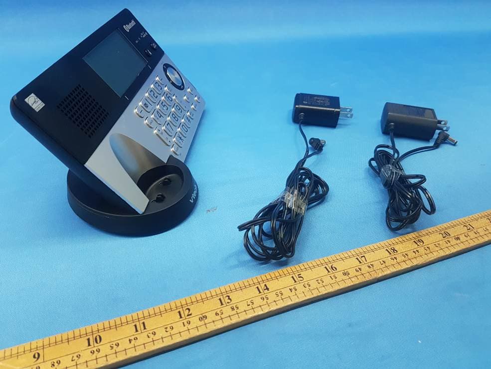
Click to zoom
Application Details
- Equipment Class
- DXX - Part 15 Low Power Communication Device Transmitter
- Date of Grant
- Mar 25, 2020
- Application Purpose
- Original Equipment
- Date of Application
- Mar 25, 2020
- Equipment Note
- DECT 6.0 Cordless Telephone - Base Unit
- Frequency Range
- 2402.00000000 - 2480.00000000
- Company
- VTech Telecommunications Ltd
- Country
- Hong Kong
Documents & Files
Document Text
Text extracted from the exhibit documents filed with the FCC. Open a document above to read the original.
Users Manual
Go to www.vtechphones.com to register your product for enhanced warranty support and the latest VTech product news. Quick start guide IS8151 IS8151-2 IS8151-3 IS8151-4 IS8151-5 IS8152-5 Specifications are subject to change without notice.© 2020 VTech Communications, Inc.All rights reserved. 03/20. IS8151-X_QSG_V1.0Document order number: 96-012956-010-100 Frequency control Crystal controlled PLL synthesizer Transmit frequency Handset: 1921.536MHz - 1928.448MHzTelephone base: 1921.536MHz - 1928.448MHz Channels 5 Nominal effective range Maximum power allowed by FCC and IC. Actual operating range may vary according to environmental conditions at the time of use. Power requirement Handset: 2.4 VDC, AAA×2, Ni-MH battery packTelephone base: 6V DC @ 600mACharger: 6V DC @ 400mA Memory Phonebook: 200 memory locations; up to 30 digits and 15 characters Caller ID log: 50 memory locations; up to 24 digits and 15 characters Call block: 1000 entries DECT 6.0 Cordless Answering System with Smart Call Blocker Telephones identified with this logo have reduced noise and interference when used with most T-coil equipped hearing aids and cochlear implants. The TIA-1083 Compliant Logo is a trademark of the Telecommunications Industry Association. Used under license. T Compatible with Hearing Aid T-Coil TIA -1083 The ENERGY STAR ® program (www.energystar.gov) recognizes and encourages the use of products that save energy and help protect our environment. We are proud to mark this product with the ENERGY STAR ® label indicating it meets the latest energy efficiency guidelines. To use a Bluetooth enabled cellular phone with your telephone, you must first pair and connect your Bluetooth cellular phone wit h the telephone base. Before you begin, make sure that you have cellular coverage and your Bluetooth enabled cell phone is not connected to any other Bluetooth device. Add a Bluetooth cell phone Activate remote voice control Download a cell phone directory using the telephone baseBefore downloading a directory, make sure the cell phone is paired, active, and connected to your IS8151. 1 Press VOICE on the handset . Technical specifications VTech Communications, Inc. and its suppliers assume no responsibility for any damage or loss resulting from the use of this user’s manual. VTech Communications, Inc. and its suppliers assume no responsibility for any loss or claims by third parties that may arise through the use of this product.Company: VTech Communications, Inc.Address: 9020 SW Washington Square Road - Ste 555 Tigard, OR 97223, United StatesPhone: 1 (800) 595-9511 in the U.S. or 1 (800) 267-7377 in CanadaDisclaimer and Limitation of Liability Bluetooth 1. If cell is connected to BT device, please disconnect it. NEXT Pls set headset to discoverable mode BACK NEXT 1 Press MENU on the telephone base . 2 Press / to scroll to Bluetooth, then press SELECT . 3 Press SELECT to select Add device . 4 Press SELECT to select Add cellular . 5 Press NEXT . 6 Press NEXT . 7 Once your cellphone finds your telephone (VTech DECT 6.0) , press appropriate key on your cell phone to continue the pairing process. 1 Press MENU on the telephone base. 2 Press / to scroll to Bluetooth, then press SELECT . 3 Press SELECT to select Add device . 4 Press / to scroll to Add headset, then press SELECT . 5 Press NEXT . 6 Press NEXT . 2 Speak toward the telephone base or handset, and then wait for feedback. 3 Press END to end . 1 Press MENU on the telephone base. 2 Press / to scroll to Bluetooth, then press SELECT . 3 Press / to scroll to Download PB, then press SELECT . 4 Press NEXT . Important safety instructionsWhen using your telephone equipment, basic safety precautions should always be followed to reduce the risk of fire, electric shock and injury, including the following:1. Read and understand all instructions. 2. Follow all warnings and instructions marked on the product. 3. Unplug this product from the wall outlet before cleaning. Do not use liquid or aerosol cleaners. Use a damp cloth for cleaning. 4. Do not use this product near water such as near a bath tub, wash bowl, kitchen sink, laundry tub or a swimming pool, nor in a wet basement or shower. 5. Do not place this product on an unstable table, shelf, stand or other unstable surfaces. 6. Avoid placing the telephone system in places with extreme temperature, direct sunlight, or other electrical devices. Protect your phone from moisture, dust, corrosive liquids and fumes. 7. Slots and openings in the back or bottom of the telephone base and handset are provided for ventilation. To protect them from overheating, these openings must not be blocked by placing the product on a soft surface such as a bed, sofa or rug. This product should never be placed near or over a radiator or heat register. This product should not be placed in any area where proper ventilation is not provided. 8. This product should be operated only from the type of power source indicated on the marking label. If you are not sure of the type of power supply in your home or office, consult your dealer or local power company. 9. Do not allow anything to rest on the power cord. Do not install this product where the cord may be walked on. 10. Never push objects of any kind into this product through the slots in the telephone base or handset because they may touch dangerous voltage points or create a short circuit. Never spill liquid of any kind on the product. 11. To reduce the risk of electric shock, do not disassemble this product, but take it to an authorized service facility. Opening or removing parts of the telephone base or handset other than specified access doors may expose you to dangerous voltages or other risks. Incorrect reassembling can cause electric shock when the product is subsequently used. 12. Do not overload wall outlets and extension cords.13. Unplug this product from the wall outlet and refer servicing to an authorized service facility under the following conditions: • When the power supply cord or p…
Text truncated - open the document above for the full version.
Cover Letter(s)
Appendix B1 Letter of Agency for FCC Certification Mar. 10, 2020 To whom it may concern, Letter of Agency I, an officer of VTech Telecommunications Limited do hereby authorize Intertek Testing Services (Mr. Terry Chan/ Kenneth Wong/ Ms. Jess Tang) to act on our behalf in front of the Federal Communications Commission with respect to all matters relating to certification of equipment under Part 15 and/or Part 95 of the FCC Rules until further notice. I further certify that no party (as defined in §1.2002(b) of CFR 47, 2004) to this application, including myself, is subject to a denial of federal benefits, that includes FCC benefits, pursuant to Section 5301 of the Anti-Drug Abuse Act of 1988, 21 U.S.C., 862. Regards, Michael Tsui Approbation Supervisor
Cover Letter(s)
VTech Telecommunications Ltd Mar. 10. 2020 To whom it may concern, Request for Permanent Confidentiality Under FCC Part 15 Certification FCC ID: EW780-2014-00 Request is hereby submitted by VTech Telecommunications Ltd. to withhold permanently from public review certain portions of the application for equipment certification for the referenced FCC identifiers. This request for confidentiality is made pursuant to 47 CFR § 0.457(d) and 0.459 of the FCC Rules. In particular, the following sections of the application are to be kept permanently confidential and VTech Telecommunications Ltd. reserves the right to discern which parties can obtain access to these information: Schematics Detailed Block diagrams Detailed Operational/Functional Description The rationale for request for confidentiality is as followings: This information represents intellectual property of VTech Telecommunications Ltd . and it is subject to competition. We have invested considerable time and materials in research and development to produce the referenced product. Disclosure of the permanently confidential portions of this application to competitors would not only give them significant competitive advantages in developing similar products, but would also disclose successful implementation of unpublished, leading edge technology developed by us. If you have questions or need further information, please contact the undersigned. Regards, Michael Tsui Approbation Supervisor
External Photos
INTERTEK TESTING SERVICES External Photos FCC ID: EW780-2014-00 IC: 1135B-80201400 INTERTEK TESTING SERVICES External Photos FCC ID: EW780-2014-00 IC: 1135B-80201400
ID Label/Location Info
IS8151-X Engraving(updated on Mar 23,2020) Model: IS8151 S/N: XXXXXXXXXXXXXXXXXXXX SN Label 28X10 mm Model: IS8151 S/N: XXXXXXXXXXXXXXXXXXXX RINGER EQUIVALENCE: 0.1A HAC USOC JACK: RJ11C/RJ11W FCC ID : EW780-2014-00 IC: 1135B-80201400 COMPLIES WITH 47 CFR PART 68 Reg. No.: US: EW7W401A80-201400 HVIN: 35-201331BS DC 6V 600mA Text : Recessed 0.3mm High Gloss Use Only Supplied Adapter 6V TEL. LINE SN Label 20X10 mm Model: IS8101 SN: XXXXXXXXXXXX IS8151-X Engraving Use Only Supplied Battery or Battery BT283342 FCC ID: EW780-2014-00 IC: 1135B-80201401 HVIN: 35-201330HS Text : Recessed 0.3mm High Gloss CHARGER Use 30-017168 tooling Use Only Supplied Adapter CORDLESS TELEPHONE DC 6V 400mA VTech Customer Service 1-800-595-9511 www.vtechphones.com CAUTION 6V I.T.E. 4H20 Accessory I.T.E. Model: IS8151 SN: XXXXXXXXXXX Model: IS8151 SN: XXXXXXXXXXX Model: IS8151-2 SN: XXXXXXXXXXX Model: IS8151-3 SN: XXXXXXXXXXX Model: IS8151-5 SN: XXXXXXXXXXX Model: IS8152-5 SN: XXXXXXXXXXX Model: IS8151-2 S/N: XXXXXXXXXXXXXXXXXXXXS/N: XXXXXXXXXXXXXXXXXXXX Model: IS8151-3 S/N: XXXXXXXXXXXXXXXXXXXXS/N: XXXXXXXXXXXXXXXXXXXX Model: IS8151-4 S/N: XXXXXXXXXXXXXXXXXXXXS/N: XXXXXXXXXXXXXXXXXXXX Model: IS8151-5 S/N: XXXXXXXXXXXXXXXXXXXXS/N: XXXXXXXXXXXXXXXXXXXX Model: IS8151-4 SN: XXXXXXXXXXX Model: IS8152-5 S/N: XXXXXXXXXXXXXXXXXXXXS/N: XXXXXXXXXXXXXXXXXXXX
Internal Photos
INTERTEK TESTING SERVICES Internal photos FCC ID: EW780-2014-00 IC: 1135B-80201400 INTERTEK TESTING SERVICES Internal photos FCC ID: EW780-2014-00 IC: 1135B-80201400 INTERTEK TESTING SERVICES Internal photos FCC ID: EW780-2014-00 IC: 1135B-80201400 INTERTEK TESTING SERVICES Internal photos FCC ID: EW780-2014-00 IC: 1135B-80201400 INTERTEK TESTING SERVICES Internal photos FCC ID: EW780-2014-00 IC: 1135B-80201400 INTERTEK TESTING SERVICES Internal photos FCC ID: EW780-2014-00 IC: 1135B-80201400 INTERTEK TESTING SERVICES Internal photos FCC ID: EW780-2014-00 IC: 1135B-80201400 INTERTEK TESTING SERVICES Internal photos FCC ID: EW780-2014-00 IC: 1135B-80201400 INTERTEK TESTING SERVICES Internal photos FCC ID: EW780-2014-00 IC: 1135B-80201400
RF Exposure Info
INTERTEK TESTING SERVICES FCC ID: EW780-2014-00 RF exposure - 1 of 1 For Maximum Permissible Exposure (MPE) evaluation of the base unit, the maximum power density at 20 cm from this mobile transmitter shall be less than the General Population / Uncontrolled MPE limit in OET Bulletin 65 and meet the requirement listed in KDB447498. For the 1.9GHz DECT Transmission of tested model: IS8151-4, the measured powers among all the measured channels were within its production tolerance: +16 dBm (Minimum) and +21 dBm (Maximum). The antenna gain of IS8151-4 is 2 dBi = 1.58 (num gain) and its maximum source-based time-averaging duty factor is 25.0% (6/24 x100%). From these data and its operating configuration – Mobile device, the exposed power density at a distance (R) of 20cm from the center of radiation of the antenna can be calculated according to OET Bulletin 65 as follow: The Conducted Power = 21 dBm = 125.9 mW The Conducted Power source-based time-averaging output power = (125.9 * 0.250) mW = 31.47 mW The power density at 20cm = 31.47 *1.58/ 4πR 2 = 0.0099 mW cm -2 For the 2.4GHz Bluetooth Transmission of tested model: IS8151-4, the measured powers among all the measured channels were within its production tolerance: -6 dBm (Minimum) and +4 dBm (Maximum). The antenna gain of IS8151-4 is 0 dBi = 1.00 (num gain) and its maximum source-based time-averaging duty factor is 83.3% (5/6 x100%). From these data and its operating configuration – Mobile device, the exposed power density at a distance (R) of 20cm from the center of radiation of the antenna can be calculated according to OET Bulletin 65 as follow: The Conducted Power = 4 dBm = 2.5 mW The Conducted Power source-based time-averaging output power = (2.5 * 0.833) mW = 2.09 mW The power density at 20cm = 2.09 *1.00/ 4πR 2 = 0.0004 mW cm -2 INTERTEK TESTING SERVICES FCC ID: EW780-2014-00 RF exposure - 1 of 1 Per KDB 447498 D01 v06, simultaneous transmission MPE test exclusion applies when the sum of the MPE ratios for all simultaneous transmitting antennas incorporated in a host device, based on calculated or measured field strengths or power density, is ≤ 1.0. The MPE ratio for DECT Transmission can be calculated as follow: = The power density at 20cm / MPE limit = 0.0099 mW cm -2 / 1.0 mW cm -2 = 0.0099 The MPE ratio for Bluetooth Transmission can be calculated as follow: = The power density at 20cm / MPE limit = 0.0004 mW cm -2 / 1.0 mW cm -2 = 0.0004 The sum of the MPE ratios for all simultaneous transmitting antennas = 0.0099 + 0.0004 = 0.0103 As the sum of MPE ratios for all simultaneous transmitting antennas is ≤ 1.0, simultaneous transmission MPE test exclusion will be applied. Conclusion In frequency range of 1,500 - 100,000MHz, the MPE limit is 1.0 mWcm -2 for general population and uncontrolled exposure. As simultaneous transmission MPE test exclusion is applied and the measured power density at 20cm from all the standalone transmissions is lower than the MPE limit, the compliance to the MPE limit can be ensured by indicating the minimum 20cm separation between the transmitter's radiating structures and body of the user or nearby persons. The following RF exposure statement is proposed to be included in the user manual: “ FCC RF Radiation Exposure Statement Caution: To maintain compliance with the FCC’s RF exposure guidelines, place the base unit at least 20cm from nearby persons.”
Test Report
2/F., Garment Centre, 576 Castle Peak Road, Kowloon, Hong Kong SAR, China. Telephone: (852) 2173 8888 Facsimile: (852) 2785 5487 www.intertek.com Intertek’s standard Terms and Conditions can be obtained at our website http://www.intertek.com/terms/. The test report only allows to be revised within the retention period unless further standard or the requirement was noticed. This report is for the exclusive use of Intertek's Client and is provided pursuant to the agreement between Intertek and its Client. Intertek's responsibility and liability are limited to the terms and conditions of the agreement. Intertek assumes no liability to any party, other than to the Client in accordance with the agreement, for any loss, expense or damage occasioned by the use of this report. Only the Client is authorized to permit copying or distribution of this report and then only in its entirety. Any use of the Intertek name or one of its marks for the sale or advertisement of the tested material, product or service must first be approved in writing by Intertek. The observations and test results in this report are relevant only to the sample tested. This report by itself does not imply that the material, product, or service is or has ever been under an Intertek certification program. © 2017 Intertek Page 1 of 27 TEST REPORT Report No.: 20020416HKG-005 Application For Original Grant of 47 CFR Part 15 Certification Single New of RSS-210 Issue 10 Equipment Certification DECT 6.0 Cordless Telephone - Base Unit FCC ID: EW780-2014-00 IC: 1135B-80201400 Prepared and Checked by: Approved by: Signed On File Leung Chiu Kuen, Stanley Engineer Tang Kwan Mo, Jess Lead Engineer Date: March 24, 2020 TEST REPORT VTech Telecommunications Ltd. Intertek Report No: 20020416HKG-005.doc Page 2 of 27 GENERAL INFORMATION Grantee: VTech Telecommunications Ltd. Grantee Address: 23/F., Tai Ping Industrial Centre, Block 1, 57 Ting Kok Road, Tai Po, Hong Kong. FCC Specification Standard: FCC Part 15, October 1, 2018 Edition FCC ID: EW780-2014-00 FCC Model(s): IS8151-4, IS8151, IS8151-2, IS8151-3, IS8151-5, IS8152-5, IS815Z-XY IC Specification Standard: RSS-210 Issue 10, December 2019 RSS-Gen Issue 5, April 2018 IC: 1135B-80201400 HVIN 35-201331BS VTech Model(s): IS8151-4, IS8151, IS8151-2, IS8151-3, IS8151-5, IS8152-5 PMN IS8151/IS8151-2/IS8151-3/IS8151-4/IS8151-5/IS8152-5 Type of EUT: Transceiver Description of EUT: DECT 6.0 Cordless Telephone - Base Unit Serial Number: N/A Sample Receipt Date: February 27, 2020 Date of Test: March 1 - 20, 2020 Report Date: March 24, 2020 Environmental Conditions: Temperature: +10 to 40°C Humidity: 10 to 90% Conclusion: Test was conducted by client submitted sample. The submitted sample as received complied with the 47 CFR Part 15 / RSS-210 Issue 10 Certification. TEST REPORT VTech Telecommunications Ltd. Intertek Report No: 20020416HKG-005.doc Page 3 of 27 TABLE OF CONTENTS 1.0 TEST RESULTS SUMMARY & STATEMENT OF COMPLIANCE ............................................ 4 1.1 Summary of Test Results ................................................................................................. 4 1.2 Statement of Compliance ................................................................................................ 4 2.0 GENERAL DESCRIPTION ................................................................................................ 5 2.1 Product Description......................................................................................................... 5 2.2 Test Methodology ........................................................................................................... 5 2.3 Test Facility ..................................................................................................................... 5 3.0 SYSTEM TEST CONFIGURATION ..................................................................................... 6 3.1 Justification ..................................................................................................................... 6 3.2 EUT Exercising Software .................................................................................................. 7 3.3 Radiated Emission Test Setup ......................................................................................... 8 3.4 Conducted Emission Test Setup ...................................................................................... 9 3.5 Details of EUT and Description of Accessories ............................................................... 10 3.6 Measurement Uncertainty ............................................................................................ 10 4.0 TEST RESULTS ............................................................................................................. 11 4.1 Field Strength Calculation.............................................................................................. 11 4.2 Radiated Emissions........................................................................................................ 12 4.2.1 Radiated Emission Configuration Photograph ............................................................ 12 4.2.2 Radiated Emission Data .............................................................................................. 12 4.2.3 Transmitter Duty Cycle Calculation ............................................................................ 18 4.3 Radiated Emission on the Bandedge ............................................................................. 19 4.4 AC Power Line Conducted Emission .............................................................................. 22 4.4.1 AC Power Line Conducted Emission Configuration Photograph ................................. 22 4.4.2 AC Power Line Conducted Emission Data ................................................................... 22 5.0 EQUIPMENT LIST ........................................................................................................ 27 TEST R…
Text truncated - open the document above for the full version.
Test Setup Photos
INTERTEK TESTING SERVICES The Worst Case Configuration Photographs FCC ID: EW780-2014-00 IC: 1135B-80201400 Radiated Emission - Bluetooth Front View Rear View INTERTEK TESTING SERVICES The Worst Case Configuration Photographs FCC ID: EW780-2014-00 IC: 1135B-80201400 Radiated Emission - Dect Front View Rear View INTERTEK TESTING SERVICES The Worst Case Configuration Photographs FCC ID: EW780-2014-00 IC: 1135B-80201400 AC Conducted Emission - Bluetooth Front View Side View 1 INTERTEK TESTING SERVICES The Worst Case Configuration Photographs FCC ID: EW780-2014-00 IC: 1135B-80201400 AC Conducted Emission Side View 2 INTERTEK TESTING SERVICES The Worst Case Configuration Photographs FCC ID: EW780-2014-00 IC: 1135B-80201400 AC Conducted Emission - Dect Front View Side View 1 INTERTEK TESTING SERVICES The Worst Case Configuration Photographs FCC ID: EW780-2014-00 IC: 1135B-80201400 AC Conducted Emission Side View 2
Contact Information
Applicant
Michael Tsui(Approbation Supervisor)
Technical Contact
Intertek Testing Services Hong Kong Ltd.Terry Chan
[email protected](852) 2173 8888
2/F., Garment Centre, · Hong Kong
Non-Technical Contact
Intertek Testing Services Hong Kong Ltd.Terry Chan
[email protected](852) 2173 8888
Test Firm
Intertek Testing Services Hong Kong Ltd.Billy Chow
Technical Specifications
| # | Rule Parts | Frequency Range | Power Output |
|---|---|---|---|
| 1 | 15C | 2.40 GHz - 2.48 GHz | - |
Other Applications from VTech Telecommunications Ltd

EW780-2531-01
Sep 12, 2024Video Baby Monitor
Equipment Class
DSS - Part 15 Spread Spectrum Transmitter
EW780-2531-00
Sep 12, 2024Video Baby Monitor
Equipment Class
DXX - Part 15 Low Power Communication Device Transmitter
EW780-2792-00A
Sep 09, 2024Video Baby Monitor
Equipment Class
DSS - Part 15 Spread Spectrum Transmitter
EW780-H0HQ-13
Aug 20, 2024SIP cordless hotel phone
Equipment Class
PUB - Part 15 Unlicensed PCS Base Station
EW780-2365-00A
Aug 19, 2024Video Baby Monitor
Equipment Class
DSS - Part 15 Spread Spectrum Transmitter