EW780-2754-00Video Monitor - Baby Unit
VTech Telecommunications Ltd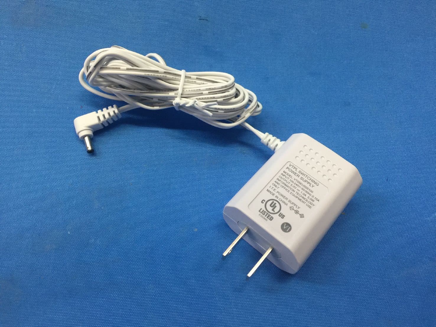
Click to zoom
Application Details
- Equipment Class
- DTS - Digital Transmission System
- Date of Grant
- Jun 14, 2022
- Application Purpose
- Original Equipment
- Date of Application
- Jun 14, 2022
- Equipment Note
- Video Monitor - Baby Unit
- Frequency Range
- 2412.00000000 - 2462.00000000
- Company
- VTech Telecommunications Ltd
- Country
- Hong Kong
Documents & Files
Document Text
Text extracted from the exhibit documents filed with the FCC. Open a document above to read the original.
Users Manual
Go to www.vtechphones.com to register your product for enhanced warranty support and latest VTech product news. Congratulations on purchasing your new VTech product. Before using this video monitor, please read Important safety instructions. For support, shopping, and everything new at VTech, visit our website at www.vtechphones.com. In Canada, visit www.vtechcanada.com. FrequencyBaby unit: 2412 - 2462 MHz Channels11 LCD5’’ Color LCD (IPS 320x240 pixels) Nominal effective rangeMaximum power allowed by FCC and IC. Actual operating range may vary according to environmental conditions at the time of use. Power requirementParent unit/Baby unit power adapters: VTech, VT05EUS05100 Rated output: 5V DC, 1000mA. Parent unit battery: 3.6V 2600mAh, 9.36Wh Lithium-ion battery Specifications are subject to change without notice. © 2022 VTech Communications, Inc. All rights reserved. 04/22. RM2851_QSG_V1 Technical specifications Android TM and Google Play TM are trademarks of Google Inc. App Store is a trademark of Apple Inc., registered in the U.S. and other countries. IOS is a trademark or registered trademark of Cisco in the U.S. and other countries and is used under license. UL STD. 62368-1 CERTIFIED TO CSA STD. C22.2 NO.62368-1 CONFORMS TO RM2851 RM2851-2 2.8 inch Smart Wi-Fi 1080p Video Monitor What does Video Monitor do? VTech 2.8 inch Smart Wi-Fi 1080p Video Monitor allows you to stay close to your baby when you are on the move or away. This monitor is Wi-Fi enabled, which uses your home wireless network to stream live video and audio through the baby unit and 2.8 inch color screen parent unit. It allows you to maintain a constant connection to your baby. You can also monitor from your smartphone and mobile tablet. VTech 2.8 inch Smart Wi-Fi 1080p Video Monitor uses MyVTech Baby Pro app to let you instantly see and hear what’s happening with your baby from anywhere in the world. The app can be downloaded from the App Store or the Google Play TM Store, directly from your smartphone or mobile tablet. Disclaimer and Limitation of Liability VTech Communications, Inc. and its suppliers assume no responsibility for any damage or loss resulting from the use of this user’s manual. VTech Communications, Inc. and its suppliers assume no responsibility for any loss or claims by third parties that may arise through the use of this product. Company: VTech Communications, Inc. Address: 9020 SW Washington Square Road - Ste 555 Tigard, OR 97223, United States Phone: 1 (800) 595-9511 in the U.S. or 1 (800) 267-7377 in Canada Quick start guide RM2851 For more support information S m RM2851-2 Direct mode The parent unit and the baby unit of your video monitor connect to each others in Direct mode by default, which allows you to stream live video right out of the box. Direct mode connection lets you stream live video from parent unit only. • You may experience reduced signal strength if your parent unit and baby unit are far apart, or there are obstructing factors, such as internal walls, between them. Move the parent unit closer to the baby unit to improve the signal strength. You can also set up Router mode to connect via your home Wi-Fi network to improve the connection between your parent unit and baby unit. Router mode You can continue using your video monitor with Direct mode connection, or you can set up your monitor in Router mode connection. Router mode uses your home Wi-Fi network to connect your video monitor. It supports streaming live video through parent unit and smartphone app. We recommend that you set up your monitor in Router mode to enjoy streaming live video via your parent unit with better connection. If you want to stream live video remotely with your mobile device, download and install the MyVTech Baby Pro mobile app. With the mobile app, your Wi-Fi router (not included) provides Internet connectivity to your video monitor system. It serves as a communicating channel between your baby unit and mobile device, allowing you to monitor and/or control your baby unit wherever you are. For detail, see Download app for mobile access section in this quick start guide. Notes • Your parent unit detects the connection signal strength. If you have connected your video monitor with your home Wi-Fi network, your parent unit automatically switches to direct or router mode - the one that has stronger signal strength. • When both parent unit and app are viewing the camera simultaneously, the video quality will be optimised to deliver the best possible viewing result. Overview What’s in the box Connect, charge and power on the baby monitor CABLE MANAGEMENT x 2 x 2 Important safety instructions Quick start guide Your video monitor package contains the following items. Save your sales receipt and original packaging in the event warranty service is necessary. How the system works VTech cares about your privacy and peace of mind. That’s why we’ve put together a list of industry- recommended best practices to help keep your wireless connection private and your devices protected when online. We recommend you carefully review and consider complying with the following tips. Ensure your wireless connection is secure. • Before installing a device, ensure your router’s wireless signal is encrypted by selecting the “WPA2- PSK with AES” setting in your router’s wireless security menu. Change default settings. • Change your wireless router’s default wireless network name (SSID) to something unique. • Change default passwords to unique, strong passwords. A strong password: - Is at least 10 characters long. - Is complex. - Does not contain dictionary words or personal information. - Contains a mix of uppercase letters, lowercase letters, special characters and numbers. Keep your devices up to date. • Download security patches from manufacturers as soon as they become available. This will ensure you always have the latest security updates. • If the feature is available, enable automatic updates for future releases. Disable Un…
Text truncated - open the document above for the full version.
Users Manual
To keep this product working well and looking good, follow these guidelines: • Avoid putting it near heating appliances and devices that generate electrical noise (for example, motors or fluorescent lamps). • DO NOT expose it to direct sunlight or moisture. • Avoid dropping the product or treating it roughly. • Clean with a soft cloth. • DO NOT immerse the parent unit and the baby unit in water and do not clean them under the tap. • DO NOT use cleaning spray or liquid cleaners. • Make sure the parent unit and the baby unit are dry before you connect them to the mains again. • Clean the USB charging port of dust, dirt, and lint regularly. When you are not going to use the video monitor for some time, store the parent unit, the baby unit and the adapters in a cool and dry place. Below are the questions most frequently asked about the video monitor. Can I turn off the parent unit screen but keep hearing sound from the baby unit? The parent unit’s LCD display will dim automatically after being inactive for some time. Press MENU/SELECT will turn the LCD display back on. Why does the baby unit not respond normally? Try the following (in the order listed) for common cure: 1. Disconnect the power to the baby unit. 2. Wait a few minutes before connecting power back to the baby unit. 3. Reboot the parent unit. Why is my screen in black and white? The baby unit has a light sensor that measures the ambient light. When the ambient light is dim, such as during nighttime or in a dark room, the baby unit activates its infrared LEDs, and displays the camera view in black and white. Why does my baby unit show offline? Why is the connection lost every now and then? The baby unit may lose the Internet connection. Check your network and the router setting. Other electronic products may cause interference with your baby unit. Try installing your baby unit as far away from these electronic devices as possible. Why don’t I hear a sound/Why can’t I hear my baby cry? The parent unit speaker volume may be too low. Press VOL + to increase the volume. You may have set a low sound sensitivity level. Set the sound sensitivity to a higher level. For details, go to www.vtechphones.com for online help topics. Frequently asked questions General product care Storage mount the baby unit (optional) 1. Place the wall mount bracket on a wall and then use a pencil to mark two holes in parallel. Remove the wall mount bracket and drill two holes in the wall (7/32 inch drill bit). NOTESNOTE Notes • Check for reception strength and camera angle of the baby unit before drilling the holes. • The types of screws and anchors you need depend on the composition of the wall. You may need to purchase the screws and anchors separately to mount your baby units. 2. If you drill the holes into a stud, go to step 3. • If you drill the holes into an object other than a stud, insert the wall anchors into the holes. Tap gently on the ends with a hammer until the wall anchors are flush with the wall. 3. Align the wall mount bracket and screws with the holes in the wall as shown. Tighten the screw in the middle hole first, so that the wall mount bracket position is fixed. You can tighten the other screw in the top hole. 3. Insert the screws into the holes and tighten the screws until only 1/4 inch of the screws are exposed. 4. Place the baby unit on the wall mount bracket, and then slide it forward until it locks into place. Align the holes on the wall mount bracket with the screws on the wall, and slide the wall mount bracket down until it locks into place. OR 4. Place the baby unit on the wall mount bracket, and then slide it forward until it locks into place. Connect the power adapter to the baby unit and a power supply not controlled by a wall switch. Need help? Use your smartphone or mobile device to access our online help. • Go to https://help.vtechphones.com/rm2851 or https://help.vtechphones.com/rm2851-2 ; OR • Scan the QR code on the right. Launch the camera app or QR code scanner app on your smartphone or tablet. Hold the device’s camera up to the QR code and frame it. Tap the notification to trigger the redirection of the online help. -If the QR code is not clearly displayed, adjust your camera’s focus by moving your device closer or further away until it is clear. If you would like to contact us, visit https://help.vtechphones.com/cs. Download app for mobile access Test the sound level and position the video monitor S m You can also call our Customer Support at 1-844-848-8324 (1-844-84-VTECH) [in US] or 1-888-211-2005 [in Canada] for help. Driven by system updates, the software, online help topics, and online FAQs will be updated periodically. For operations and guides to help you using your video monitor, and for latest information and supports, go and check the online help topics and online FAQs. Auto software and firmware update If you plan to install your baby unit in a designated location, and use your home Wi-Fi network to connect your video monitor, you need to test which of your selected monitoring areas within the house have good Wi-Fi signal strength. After you have powered on your parent unit, you can use your parent unit’s Wi-Fi signal strength indicator to assist in checking. Once you have identified the suitable location, you can install your baby unit. Adjust the distance between your baby unit and the Wi-Fi router if needed. • Depending on surroundings and obstructing factors, such as the effect distance and internal walls have on signal strength, you may experience reduced Wi-Fi signal. To improve the Wi-Fi signal strength, adjust the distance or direction of your parent unit. Check with your parent unit again. test the location for the baby unit Note • This video monitor is intended as an aid. It is not a substitute for proper adult supervision, and should not be used as such. Testing the sound level of the video monitor • For hearing protection, make sure the parent unit is more than 3 meters away from the baby unit. I…
Text truncated - open the document above for the full version.
Cover Letter(s)
VTech Telecommunications Ltd Appendix B1 Letter of Agency for FCC Certification Sep. 27, 2017 To whom it may concern, Letter of Agency I, an officer of VTech Telecommunications Ltd do hereby authorize Intertek Testing Services (Terry Chan/ Koo Wai Ip/ Kenneth Wong/ Jess Tang) to act on our behalf in front of the Federal Communications Commission with respect to all matters relating to certification of equipment under Part 15 and/or Part 95 of the FCC Rules until further notice. I further certify that no party (as defined in §1.2002(b) of CFR 47, 2004) to this application, including myself, is subject to a denial of federal benefits, that includes FCC benefits, pursuant to Section 5301 of the Anti-Drug Abuse Act of 1988, 21 U.S.C., 862. Regards, Michael Tsui Approbation Supervisor
Cover Letter(s)
VTech Telecommunications Ltd Oct 06, 2021 To whom it may concern, Request for Permanent Confidentiality Under FCC P art 15 Certification FCC ID: EW780-2754-00 Request is hereby submitted by VTech Telecommunications Ltd. to withhold permanently from public review certain portions of the application for equipment certification for the referenced FCC identifiers. This request for confidentiality is made pursuant to 47 CFR § 0.457(d) and 0.459 of the FCC Rules. In particular, the following sections of the application are to be kept permanently confidential and VTech Telecommunications Ltd. r eserves the right to discern which parties can obtain access to these information: •Schematics •Detailed Block diagrams •Detailed Operational/Functional Description The rationale for request for confidentiality is as followings: This information represents intellectual property of VTech Telecommunications Ltd. and it is subject to competition. We have invested considerable time and materials in research and development to produce the referenced product. Disclosure of the permanently confidential portions of this application to competitors would not only give them significant competitive advantages in developing similar products, but would also disclose successful implementation of unpublished, leading edge technology developed by us. If you have questions or need further information, please contact the undersigned. R egards, Michael Tsui Approbation Supervisor
External Photos
INTERTEK TESTING SERVICES External Photos FCC ID: EW780-2754-00 IC: 1135B-80275400 INTERTEK TESTING SERVICES External Photos FCC ID: EW780-2754-00 IC: 1135B-80275400
ID Label/Location Info
PU BU SIZE: 36.4X16.4 mm SIZE: 29.4X10 mm S/N: XXXXXXXXXXX Model: RM2851 BU www.vtechphones.com VTech Customer Service 1-844-848-8324 FCC ID: EW780-2754-00 IC: 1135B-80275400 HVIN: 35-400427BU UPC: 7-3507805310-7 DiSa: xxxxxxxxxxxxx WIFI MAC: XXXXXX S/N: XXXXXXXXXXX Model: RM2851-2 BU www.vtechphones.com VTech Customer Service 1-844-848-8324 FCC ID: EW780-2754-00 IC: 1135B-80275400 HVIN: 35-400427BU UPC: 7-3507805310-7 DiSa: xxxxxxxxxxxxx WIFI MAC: XXXXXX S/N: XXXXXXXXXXX Model: RM2751 BU www.vtechphones.com VTech Customer Service 1-844-848-8324 FCC ID: EW780-2754-00 IC: 1135B-80275400 HVIN: 35-400427BU UPC: 7-3507805310-7 DiSa: xxxxxxxxxxxxx WIFI MAC: XXXXXX S/N: XXXXXXXXXXX Model: RM2751-2 BU www.vtechphones.com VTech Customer Service 1-844-848-8324 FCC ID: EW780-2754-00 IC: 1135B-80275400 HVIN: 35-400427BU UPC: 7-3507805310-7 DiSa: xxxxxxxxxxxxx WIFI MAC: XXXXXX S/N: XXXXXXXXXXX Model: RM2851 BU www.vtechphones.comVTech Customer Service1-844-848-8324 FCC ID: EW780-2754-00IC: 1135B-80275400HVIN: 35-400427BUUPC: 7-3507805310-7 DiSa: xxxxxxxxxxxxx WIFI MAC: XXXXXX A/V I.C.T.E. Model: RM2851 PU S/N: XXXXXXXXXXX HVIN: 35-201927PU MANUFACTURED IN CHINA FCC ID: EW780-2754-01 IC: 1135B-80275401 UPC: 7-3507805310-7 DiSa: xxxxxxxxxxxxx WIFI MAC: XXXXXX A/V I.C.T.E. Model: RM2851 PU S/N: XXXXXXXXXXX HVIN: 35-201927PU MANUFACTURED IN CHINA FCC ID: EW780-2754-01 IC: 1135B-80275401 UPC: 7-3507805310-7 DiSa: xxxxxxxxxxxxx WIFI MAC: XXXXXX A/V I.C.T.E. Model: RM2851-2 PU S/N: XXXXXXXXXXX HVIN: 35-201927PU MANUFACTURED IN CHINA FCC ID: EW780-2754-01 IC: 1135B-80275401 UPC: 7-3507805310-7 DiSa: xxxxxxxxxxxxx WIFI MAC: XXXXXX A/V I.C.T.E. Model: RM2751 PU S/N: XXXXXXXXXXX HVIN: 35-201927PU MANUFACTURED IN CHINA FCC ID: EW780-2754-01 IC: 1135B-80275401 UPC: 7-3507805310-7 DiSa: xxxxxxxxxxxxx WIFI MAC: XXXXXX A/V I.C.T.E. Model: RM2751-2 PU S/N: XXXXXXXXXXX HVIN: 35-201927PU MANUFACTURED IN CHINA FCC ID: EW780-2754-01 IC: 1135B-80275401 UPC: 7-3507805310-7 DiSa: xxxxxxxxxxxxx WIFI MAC: XXXXXX A/V I.C.T.E. Model: RM2771 PU S/N: XXXXXXXXXXX HVIN: 35-201927PU MANUFACTURED IN CHINA FCC ID: EW780-2754-01 IC: 1135B-80275401 UPC: 7-3507805310-7 DiSa: xxxxxxxxxxxxx WIFI MAC: XXXXXX A/V I.C.T.E. Model: RM2771-2 PU S/N: XXXXXXXXXXX HVIN: 35-201927PU MANUFACTURED IN CHINA FCC ID: EW780-2754-01 IC: 1135B-80275401 UPC: 7-3507805310-7 DiSa: xxxxxxxxxxxxx WIFI MAC: XXXXXX
Internal Photos
INTERTEK TESTING SERVICES Internal photos FCC ID: EW780-2754-00 IC: 1135B-80275400 INTERTEK TESTING SERVICES Internal photos FCC ID: EW780-2754-00 IC: 1135B-80275400 INTERTEK TESTING SERVICES Internal photos FCC ID: EW780-2754-00 IC: 1135B-80275400 INTERTEK TESTING SERVICES Internal photos FCC ID: EW780-2754-00 IC: 1135B-80275400 INTERTEK TESTING SERVICES Internal photos FCC ID: EW780-2754-00 IC: 1135B-80275400 INTERTEK TESTING SERVICES Internal photos FCC ID: EW780-2754-00 IC: 1135B-80275400
RF Exposure Info
INTERTEK TESTING SERVICES FCC ID: EW780-2754-00 RF exposure - 1 of 1 For Maximum Permissible Exposure (MPE) evaluation of the baby unit, the maximum power density at 20 cm from this mobile transmitter shall be less than the General Population / Uncontrolled MPE limit in OET Bulletin 65 and meet the requirement listed in KDB447498. For the 2.4GHz Video Monitor - Baby Unit of tested model: RM2851 BU, the measured powers among all the measured channels were within its production tolerance: +15 dBm (Minimum) and +21 dBm (Maximum).The antenna gain of RM2851 BU is 2 dBi = 1.58 (num gain) and its maximum source-based time-averaging duty factor is 100.0% (100/100 x100%). From these data and its operating configuration – Mobile device, the exposed power density at a distance (R) of 20cm from the center of r adiation of the antenna can be calculated according to OET Bulletin 65 as follow: The C onducted Power = 21 dBm = 125.89 mW The Conducted Power source-based time-averaging output power = (125.89 * 1.000) mW = 125.89 mW The pow er density at 20cm = 125.89 *1.58/ 4πR 2 = 0.04 mW cm -2 In the frequency range of 1,500 - 100,000MHz, the MPE limit is 1.0 mWcm -2 for general population and uncontrolled exposure. As the measured power density at 20cm from the transmitter is lower than the MPE limit, the compliance to the MPE limit can be ensured by indicating the minimum 20cm separation between the transmitter's radiating structures and body of the user or nearby persons. The following RF exposure statement is proposed to be included in the user manual: “ FCC RF Radiation Exposure Statement Caution: To maintain compliance with the FCC’s RF exposure guidelines, place the baby unit at least 20cm from nearby persons.”
Test Report
2/F., Garment Centre, 576 Castle Peak Road, Kowloon, Hong Kong SAR, China. Telephone: (852) 2173 8888 Facsimile: (852) 2785 5487 www.intertek.com Intertek’s standard Terms and Conditions can be obtained at our website http://www.intertek.com/terms/. The test report only allows to be revised within the retention period unless further standard or the requirement was noticed. This report is for the exclusive use of Intertek's Client and is provided pursuant to the agreement between Intertek and its Client. Intertek's responsibility and liability are limited to the terms and conditions of the agreement. Intertek assumes no liability to any party, other than to the Client in accordance with the agreement, for any loss, expense or damage occasioned by the use of this report. Only the Client is authorized to permit copying or distribution of this report and then only in its entirety. Any use of the Intertek name or one of its marks for the sale or advertisement of the tested material, product or service must first be approved in writing by Intertek. The observations and test results in this report are relevant only to the sample tested. This report by itself does not imply that the material, product, or service is or has ever been under an Intertek certification program. © 2017 Intertek Page 1 of 57 TEST REPORT Report Number: 22040864HKG-002 Application for Original Grant of 47 CFR Part 15 Certification New Family of RSS-247 Issue 2 Equipment FCC ID: EW780-2754-00 IC: 1135B-80275400 Prepared and Checked by: Approved by: Signed On File Wong Cheuk Ho, Herbert Lead Engineer Tang Kwan Mo, Jess Lead Engineer Date: April 27, 2022 TEST REPORT VTech Telecommunications Ltd. Intertek Report No: 22040864HKG-002 Page 2 of 57 GENERAL INFORMATION Applicant Name: VTech Telecommunications Ltd. Applicant Address: 23/F., Tai Ping Industrial Centre, Block 1, 57 Ting Kok Road, Tai Po, Hong Kong. Manufacturer Name: VTech (Dongguan) Telecommunications Limited. Manufacturer Address: VTech Science Park, Xia Ling Bei Management Zone, Liaobu, Dongguan, Guangdong, China. FCC Specification Standard: FCC Part 15, October 1, 2020 Edition FCC ID: EW780-2754-00 FCC Model(s): RM2851 BU, RM2851-2 BU, RM2751 BU, RM2751-2 BU IC Specification Standard: RSS-247 Issue 2, February 2017 RSS-Gen Issue 5 Amendment 2, February 2021 IC: 1135B-80275400 PMN: RM2851 BU, RM2851-2 BU, RM2751 BU, RM2751-2 BU HVIN: 35-400427BU VTech Model(s): RM2851 BU, RM2851-2 BU, RM2751 BU, RM2751-2 BU Type of EUT: Spread Spectrum Transmitter Description of EUT: Video Monitor - Baby Unit Serial Number: N/A Sample Receipt Date: April 21, 2022 Date of Test: April 21 - 27, 2022 Report Date: April 27, 2022 Environmental Conditions: Temperature: +10 to 40°C Humidity: 10 to 90% Conclusion: Test was conducted by client submitted sample. The submitted sample as received complied with the 47 CFR Part 15 / RSS-247 Issue 2 Certification. TEST REPORT VTech Telecommunications Ltd. Intertek Report No: 22040864HKG-002 Page 3 of 57 TABLE OF CONTENTS 1.0 TEST RESULTS SUMMARY & STATEMENT OF COMPLIANCE ............................................ 4 1.1 Summary of Test Results ................................................................................................. 4 1.2 Statement of Compliance ................................................................................................ 4 2.0 GENERAL DESCRIPTION ................................................................................................ 5 2.1 Product Description ....................................................................................................... 5 2.2 Test Methodology ........................................................................................................... 6 2.3 Test Facility ..................................................................................................................... 6 2.4 Related Submittal(s) Grants ............................................................................................ 6 3.0 SYSTEM TEST CONFIGURATION .................................................................................... 7 3.1 Justification ..................................................................................................................... 7 3.2 EUT Exercising Software .................................................................................................. 8 3.3 Details of EUT and Description of Accessories ................................................................. 9 3.4 Measurement Uncertainty .............................................................................................. 9 4.0 TEST RESULTS ............................................................................................................ 10 4.1 Maximum Conducted Output Power at Antenna Terminals ......................................... 10 4.2 Minimum 6dB RF Bandwidth......................................................................................... 12 4.3 Maximum Power Spectral Density ................................................................................ 19 4.4 Out of Band Conducted Emissions ................................................................................ 26 4.5 Field Strength Calculation.............................................................................................. 39 4.6 Transmitter Radiated Emissions in Restricted Bands and Spurious Emissions ............... 40 4.6.1 Radiated Emission Configuration Photograph ............................................................ 40 4.6.2 Radiated Emission Data .............................................................................................. 40 4.6.3 Radiated Emission Test Setup ..................................................................................... 51 4.6.4 Transmitter Duty Cycle Calculation ............................................................................ 52 4.7 AC Power Line Conducted Emission .................…
Text truncated - open the document above for the full version.
Test Setup Photos
INTERTEK TESTING SERVICE Report No: HK22040864 Configuration Photographs Worst-Case Radiated Emissions (Front View) INTERTEK TESTING SERVICE Report No: HK22040864 Configuration Photographs Worst-Case Radiated Emissions (Rear View) INTERTEK TESTING SERVICES The Worst Case Configuration Photographs FCC ID: EW780-2754-00 IC: 1135B-80275400 Radiated Emission Front View Rear View INTERTEK TESTING SERVICES The Worst Case Configuration Photographs FCC ID: EW780-2754-00 IC: 1135B-80275400 AC Conducted Emission Front View Side View 1 INTERTEK TESTING SERVICES The Worst Case Configuration Photographs FCC ID: EW780-2754-00 IC: 1135B-80275400 AC Conducted Emission Side View 2
Contact Information
Applicant
Michael Tsui(Approbation Supervisor)
Technical Contact
Intertek Testing Services Hong Kong Ltd.Kenneth Wong
[email protected](852) 3912 6902
2/F., Garment Centre, · Hong Kong
Non-Technical Contact
Intertek Testing Services Hong Kong Ltd.Kenneth Wong
[email protected](852) 3912 6902
Test Firm
Intertek Testing Services Hong Kong Ltd.Billy Chow
Technical Specifications
| # | Rule Parts | Frequency Range | Power Output |
|---|---|---|---|
| 1 | 15C | 2.41 GHz - 2.46 GHz | 102.80 mW |
Other Applications from VTech Telecommunications Ltd

EW780-2531-01
Sep 12, 2024Video Baby Monitor
Equipment Class
DSS - Part 15 Spread Spectrum Transmitter
EW780-2531-00
Sep 12, 2024Video Baby Monitor
Equipment Class
DXX - Part 15 Low Power Communication Device Transmitter
EW780-2792-00A
Sep 09, 2024Video Baby Monitor
Equipment Class
DSS - Part 15 Spread Spectrum Transmitter
EW780-H0HQ-13
Aug 20, 2024SIP cordless hotel phone
Equipment Class
PUB - Part 15 Unlicensed PCS Base Station
EW780-2365-00A
Aug 19, 2024Video Baby Monitor
Equipment Class
DSS - Part 15 Spread Spectrum Transmitter