EW780-5125-B002.4 GHz Analog Base
VTech Telecommunications Ltd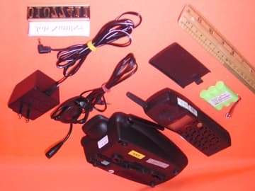
Click to zoom
Application Details
- Equipment Class
- DXX - Part 15 Low Power Communication Device Transmitter
- Date of Grant
- Aug 12, 2001
- Application Purpose
- Original Equipment
- Date of Application
- Aug 12, 2001
- Equipment Note
- 2.4 GHz Analog Base
- Frequency Range
- 2411.15000000 - 2418.40000000
- Company
- VTech Telecommunications Ltd
- Country
- Hong Kong
Documents & Files
Document Text
Text extracted from the exhibit documents filed with the FCC. Open a document above to read the original.
Users Manual
IMPORTANT PRODUCT INFORMATION Safety Information This symbol is to alert you to important operating or servicing instructions that may appear in this user’s manual. Always follow basic safety precautions when using this product to reduce the risk of injury, fire, or electric shock. 1 Read and understand all instructions in the user’s manual. Observe all markings on the product. 2 Avoid using a telephone during a thunderstorm. There may be a slight chance of electric shock from lightning. 3 Do not use a telephone in the vicinity of a gas leak. If you suspect a gas leak, report it immediately, but use a telephone away from the area where gas is leaking. If this product is a cordless model, make sure the base is also away from the area. 4 Do not use this product near water, or when you are wet. For example, do not use it in a wet basement or shower, or next to a swimming pool, bathtub, kitchen sink, or laundry tub. Do not use liquids or aerosol sprays for cleaning. If the product comes in contact with any liquids, unplug any line or power cord immediately. Do not plug the product back in until it has dried thoroughly. 5 Install this product in a protected location where no one can trip over any line or power cords. Protect cords from damage or abrasion. 6 If this product does not operate normally, read “In Case of Difficulty” in the user’s manual. If you cannot solve the problem, or if the product is damaged, refer to the Limited Warranty. Do not open this product except Part 1 (Continued) AT&T and the globe symbol are registered trademarks of AT&T Corp. licensed to Advanced American Telephones. Pt1_1yr_Eng_China_3ATT 7/18/01 10:25 AM Page 1 2 as may be directed in your user’s manual. Opening the product or reassembling it incorrectly may expose you to hazardous voltages or other risks. 7 If this product has user-replaceable batteries, replace batteries only as described in your user’s manual. Do not burn or puncture batteries — they contain caustic chemicals. 8 If this product has a three-prong (grounding) plug or a polarized plug with one wide prong, it may not fit in non-polarized outlets. Do not defeat the purpose of these plugs. If they do not fit in your outlet, the outlet should be replaced by an electrician. CAUTION:Use only the power adapter provided with this product. To obtain a replacement, call 1 800 222–3111. SAVE THESE INSTRUCTIONS Especially About Cordless Telephones Privacy: The same features that make a cordless phone convenient create some limitations. Telephone calls are transmitted between the base and the handset by radio waves, so there is a possibility that your cordless phone conversations could be intercepted by radio receiving equipment within range of the cordless handset. For this reason, you should not think of cordless phone conversations as being as private as those on corded phones. Electrical Power:The base unit of this cordless telephone must be connected to a working electrical outlet. The electrical outlet should not be controlled by a wall switch. Calls cannot be made from the handset if the base unit is unplugged or switched off, or if the electrical power is interrupted. Potential TV Interference:Some cordless telephones operate at frequencies that may cause interference to TVs and VCRs. To minimize or prevent such interference, do not place the base unit of the cordless telephone near or on top of a TV or VCR. If interference is experienced, moving the cordless telephone farther away from the TV or VCR will often reduce or eliminate the interference. (Applies to 25-channel cordless phones only.) Pt1_1yr_Eng_China_3ATT 7/18/01 10:25 AM Page 2 3 Rechargeable Batteries:This product contains either Nickel-Cadmium or Nickel-Metal Hydride rechargeable batteries. Exercise care in handling batteries in order not to short the battery with conducting material such as rings, bracelets, and keys. The battery or conductor may overheat and cause harm. Observe proper polarity between the battery and the battery charger. Nickel-Cadmium Rechargeable Batteries: Must be recycled or disposed of properly. Do not dispose of in household garbage. Do not burn or puncture. Like other batteries of this type, if burned or punctured, they could release caustic material which could cause injury. The RBRC ™ Seal means that the manufacturer is voluntarily participating in an industry program to collect and recycle Nickel- Cadmium rechargeable batteries when taken out of service within the United States. These batteries may be taken to a participating local retailer of replacement batteries or recycling center. Or you may call 1 800 8BATTERY for locations accepting spent Nickel- Cadmium Batteries. Nickel-Metal Hydride Rechargeable Batteries:Dispose of these batteries in a safe manner. Do not burn or puncture. Like other batteries of this type, if burned or punctured, they could release caustic material which could cause injury. Precautions for Users of Implanted Cardiac Pacemakers Cardiac Pacemakers (applies only to 900 MHz Digital Cordless Telephones): Wireless Technology Research, LLC (WTR), an independent research entity, led a multidisciplinary evaluation of the interference between portable wireless telephones and implanted cardiac pacemakers. Supported by the U.S. Food and Drug Administration, WTR had recommended to physicians that: PACEMAKER PATIENTS • Should keep wireless phones at least six inches from the pacemaker • Should NOTplace wireless phones directly over the pacemaker, such as in a breast pocket, when it is turned ON • Should use the wireless phone at the ear opposite the pacemaker WTR’s evaluation did not identify any risk to bystanders with pacemakers from other persons using wireless phones. Pt1_1yr_Eng_China_3ATT 7/18/01 10:25 AM Page 3 4 Especially About Telephone Answering Systems Two-Way Recording:This unit does not sound warning beeps to let the other party know that the call is being recorded. To ensure that you are in compliance with any federal or state…
Text truncated - open the document above for the full version.
Users Manual
2.4 GHz Cordless Telephone with Caller ID/Call Waiting 1430 Please also read Part 1 — Important Product Information USER’S MANUAL Part 2 AT&T and the globe symbol are registered trademarks of AT&T Corp. licensed to Advanced American Telephones. © 2001 Advanced American Telephones. All rights reserved. Printed in China. Issue 1AT&T 07/01 CONTENTS BEFORE YOU BEGIN . . . . . . . . . . . . . . .1 About Caller Identification .......... 1 INSTALLATION . . . . . . . . . . . . . . . . . . . . . . .2 Before You Install .......................... 2 Table/Desk Installation ................. 3 Wall Installation ............................ 5 TELEPHONE OPERATION . . . . . . . .6 Make a Call.................................... 6 Answer a Call ................................ 6 End a Call ...................................... 6 Change Channel............................ 6 Redial ............................................ 6 Handset Volume ............................ 6 Flash/Call Waiting.......................... 6 Hold .............................................. 6 Page/Handset Locator ................... 7 Handset Ringer Style/ Battery Save ............................... 8 Temporary Tone Dialing................ 8 Headset Jack.................................. 8 Operating Range ........................... 9 Display Screen Messages............... 9 TELEPHONE MEMORY . . . . . . . . . .10 Store a Number/Name in Memory .............................. 10 Edit a Number/Name Stored in Memory ............................... 11 Delete a Number/Name Stored in Memory ............................... 12 Dial a Memory Number .............. 12 TELEPHONE DIRECTORY . . . . . .13 Store a Number/Name in the Directory ........................... 13 Edit a Number/Name Stored the Directory ........................... 14 Delete a Number/Name Stored the Directory ........................... 15 Dial a Number from the Directory ........................... 15 CALLER ID OPERATION . . . . . . . .16 About Call History ...................... 16 Review Call History .................... 16 Delete Records from Call History .............................. 17 Dial a Displayed Number ............ 17 Store a Call History Record in the Directory ....................... 18 Display Screen Messages............. 18 BATTERIES . . . . . . . . . . . . . . . . . . . . . . . . . . .19 Charge the Handset Battery Pack............................. 19 Replacing the Handset Battery Pack............................. 20 IN CASE OF DIFFICULTY . . . . . . .21 BEFORE YOU BEGIN 1 About Caller Identification (Caller ID) This product has a Caller ID with Call Waiting feature that works with service from your local phone service provider. Caller ID with Call Waiting lets you see who’s calling before you answer the phone, even when you’re on another call. You may need to change your phone service to use this feature. Contact your phone service provider if: •You have both Caller ID and Call Waiting, but as separate services (you may need combined service) •You have only Caller ID service, or only Call Waiting service •You don’t subscribe to any Caller ID or Call Waiting services. You can use this product with regular Caller ID service, and you can use this product’s other features without subscribing to either Caller ID or combined Caller ID with Call Waiting service. There are fees for Caller ID services, and they may not be available in all areas. This product can provide information only if both you and the caller are in areas offering Caller ID service, and if both telephone companies use compatible equipment. Before You Install 1Choose a location for the base near an electrical outlet and a telephone jack. This phone requires a modular telephone jack and a standard electrical outlet (110v AC) not controlled by a wall switch. 2Install the handset battery. Use only AT&T Battery 2414, SKU#23403. INSTALLATION 2 b) Align two holes in plug with socket pins, and snap the plug into place. d) Replace cover by sliding it up into place. a)Remove battery compartment cover by pressing on the indentation and sliding downward. c) Place battery pack in compartment with the wires in the lower left corner, along the bottom of the battery pack. INSTALLATION 3 3Attach belt clip to the cordless handset (optional). To attach To remove Table/Desk Installation Standard electrical outlet Modular telephone jack 1Connect the telephone line cord. 2Connect the power cord. NOTE: Install the base unit and spare handset charger away from electronic equipment, such as personal computers, television sets or microwave ovens. Avoid excessive heat, cold, dust or moisture. INSTALLATION 4 3Charge the handset battery. Place the handset in the base. Charge the battery for at least 12 hours the first time. 4Check for dial tone. After the batteries are charged, pick up the handset and press P; you should hear a dial tone. 5Set the dial mode. If you have touch tone service, the phone is ready to use as soon as the batteries are charged. If you have dial pulse (rotary) service, you’ll need to change the dial mode. •Press Gon the handset to enter programming mode. •Press <or>until the screen displays DIAL MODE:and the currently selected mode. •Press S. The current setting blinks. •Press >to select TONEor PULSE. •Press S, to save the displayed mode. INSTALLATION 5 a)Align holes on base with mounting studs on wall jack. b) Pull base down on mounting studs until it locks into place. 4Follow Steps 3–5 in Table/Desk Installation. Wall Installation 1Connect the telephone line cord. 2Connect the power cord. 3Mount the base on the wall. Modular telephone jack Standard electrical outlet HEADLINE LEFT HEADLINE L-SUB 6 TELEPHONE OPERATION End a Call Press O — OR — Place handset in base. Exit programming. Cancel a page. Handset Volume While on a call, adjust volume of what you hear. Hold Press to put a call on hold. Press again to release hold — OR — Lift the handset of an extension. Answer a Call Press any key e…
Text truncated - open the document above for the full version.
Users Manual
VTECH TELECOMMUNICATIONS LTD. File : AT&T1430_IPS_1 Date : 07/24/01 TITLE : Internal Product Specification DOCUMENT NO. 60-5125-00-00 REV.NO. 1 PAGE 54 of 65 This document is proprietary to VTech Telecommunications Ltd. VTech HK R&D info. 5 RF Link Operation The radio frequency (RF) link is a full-duplex communication path between the AT&T1430 base and handset. It is used to transfer both audio (voice) and data between Base and Handset. There are a total of 30 RF channels available for communication. Only one channel may be selected as the active channel at any instant, though users can select to a different active channel when there is perceived interference on the current channel. 5.1 RF Link Data Data transmitted over the RF link are operational commands and CID data. When the AT&T1430 is in the PHONE mode, both audio and data will be transmitted over the RF link. To minimise any perceptible impact on audio quality when data is interspersed within the voice transmission, receiver audio at the handset will be muted within twenty (20) ms of start of data transfer. Furthermore, normal data transfers (except CID data) will be limited to no more than 150 ms in duration. When the AT&T1430 is in the STANDBY mode, the base and handset will listen for data transmission from the other relating to the initiation of the PHONE, RINGER, PROGRAM or PAGE mode. The handset is in the battery- conservation mode of operation, in which the on-board electronics is essentially “asleep” but will wake up periodically to check for incoming data transmitted from the base. The handset will detect commands sent from the base within 1 second. The first ring will be handled such that the probability of missing it is minimised. 5.2 Security Code All data communication over the RF link will include a security code as required by FCC Part 15. When a data packet is received over the RF link, the security code contained in the packet will be verified before any data is processed. This prevents the handset from receiving commands from another base unit and vice-versa. The handset and base units will use an identical, 20-bit security code. The security code is stored in the non-volatile memory in the base and handset unit and factory defaulted in production. During Production, all units will be passed through a test jig in pair. The test jig will test some parameters of the unit pair and write the security code into the memory once all test parameters passed. The test jig will count on the security code (Totally 1048576 – 20 bit buffer and reset after the buffer full) and write to the unit pair. 5.3 RF Channel Selection In order for the handset and base unit to communicate over the RF link, the selection of the active channel must be synchronised between the two units. An active channel is initially selected during the AT&T1430 initialisation process. If the RF link subsequently degrades during operation, recovery involves the selection of a new communication channel that can be manually (user) initiated. 5.3.1 Channel Resynchronization If the active channel between the Base and the Handset becomes out of synchronisation so that further communication between them cannot be established, re-cradling the Handset will re-synchronise the channel selection. It is accomplished by having the Handset transmitting the sync. code on its current channel and Base will monitor each channel sequentially until it receives the Handset’s sync. code. Upon successful reception of this signal, the Base then sends an ACK. command to Handset to confirm the current channel can communicate. BS stores the current channel as the “last channel”. Thus BS and HS resynchronisation is complete.
Block Diagram
Base audio The audio circuits in the base provide for speech exchange between the telephone line interface and the RF module that communicates with the handset. Figure 1 shows the circuitry for audio processing in the base unit. Figure 1. Audio Circuits in Base Unit TELEPHONE LINE INTERFACE RX AUDIO TX AUDIO RX DATA 4.8 kHz DE-EMPHASIS EXPANDER RECEIVER AMP COMPRESSOR PRE-EMPHASIS MIC AMP TX AUDIO AMP 1 kHz COMPARATOR TX DEVIATION CTRL RX LEVEL TX DATA TEL JACK RING DETECT SIGNAL MCU PULSE DIALLING/ OFF-HOOK SWITCH CTRL MCU MCU DTMF SIGNALS MCU DTMF SIGNALS MUTE CTRL MUTE CTRL Base RF module Figure 4. RF Circuits in Base Unit 915MHz SAW Filter X2 2.4GHz BP Filter Philips RF Combo UAA3519 (UAA3515) RX_Audio TX_Audio 10.7MHz IF Wire antenna 2.4GHz PA Q4
External Photos
External photos FCC ID: EW780-5125-B00 External photos FCC ID: EW780-5125-B00
Internal Photos
Internal photosFCC ID: EW780-5125-B00 Base assembly Base Main PCB comp s ide Internal photosFCC ID: EW780-5125-B00 Base Main PCB solder side Base Oscillator PCB co mp side Internal photosFCC ID: EW780-5125-B00 Base Oscillator PCB so lde r side
Test Report
• The test results rep orted in this rep ort shall refer only to the samp le actually tested and shall not refer or be deemed to refer to bulk from which such a samp le may be said to have been obtained. • This rep ort shall not be rep roduced excep t in full without p rior authorization form Intertek Testing Services Limit ed FCC ID: EW780-5125-B00 Inte rte k Te sting Se rvice s Hong Kong Ltd. 2/F., Garment Centre, 576 Castle Peak Road, Kowloon, Hong Kong. Tel: (852) 2173 8888 Fax: (852) 2741 1693 VTech Communications Limited Application For Certification 900MHz/2.4GHz 30 Channel Analog Modulation Cordless Phone with Caller ID (Base unit) (FCC ID: EW780-5125-B00) WO# 01077411 TL/Ann Choy July 25, 2001 INTERTEK TESTING SERVICES FCC ID: EW780-5125-B00 i LIST OF EXHIBITS INTRODUCTION EXHIBIT 1 :General Description EXHIBIT 2 :System Test Configuration EXHIBIT 3 :Emission Results EXHIBIT 4 :Equipment Photographs EXHIBIT 5 :Product Labelling EXHIBIT 6 :Technical Specifications EXHIBIT 7 :Instruction Manual EXHIBIT 8 :Security Code Information INTERTEK TESTING SERVICES FCC ID: EW780-5125-B00 ii MEASUREMENT/TECHNICAL REPORT VTech Communications Limited - MODEL: AT&T 1430 FCC ID: EW780-5125-B00 This report concerns (check one:) Original Grant X Class II Change Equipment Type : Cordless Telephone (example : computer, modem, transmitter, etc.) Deferred grant requested per 47 CFR 0.457(d)(1)(ii)?Yes No X If yes, defer until : date Company Name agrees to notify the Commission by: date of the intended date of announcement of the product so that the grant can be issued on that date. Transition Rules Request per 15.37 ?Yes No X If no, assumed Part 15, Subpart C for intentional radiator - the new 47 CFR [ 10-1-99 Edition ] Provision. Report prepared by:Tommy Leung Intertek Testing Services. 2/F., Garment Centre, 576 Castle Peak Road, Kowloon, Hong Kong. Phone :852-2173-8575 Fax:852-2741-1693 INTERTEK TESTING SERVICES FCC ID: EW780-5125-B00 iii Table of Contents 1.0 General Description ....................................................................................................... 2 1.1 Product Description.................................................................................................... 2 1.2 Related Submittal(s) Grants........................................................................................ 3 1.3 Test Methodology....................................................................................................... 3 1.4 Test Facility................................................................................................................ 3 2.0 System Test Configuration ............................................................................................. 5 2.1 Justification................................................................................................................. 5 2.2 EUT Exercising Software ........................................................................................... 5 2.3 Support Equipment List and Description ................................................................... 6 2.4 Equipment Modification............................................................................................. 7 3.0 Emission Results ............................................................................................................. 9 3.1 Field Strength Calculation ........................................................................................ 10 3.2 Radiated Emission Configuration Photograph - Base Unit ...................................... 11 3.3 Radiated Emission Data - Base Unit ........................................................................ 12 3.4 Radiated Emission on the bandedge......................................................................... 15 3.5 Line Conducted Configuration Photograph - Base Unit .......................................... 17 3.6 Line Conducted Emission Data - Base Unit ............................................................. 18 4.0 Equipment Photographs .............................................................................................. 20 5.0 Product Labelling ......................................................................................................... 22 6.0 Technical Specifications ............................................................................................... 24 7.0 Instruction Manual ....................................................................................................... 26 8.0 Security Code Information .......................................................................................... 28 INTERTEK TESTING SERVICES FCC ID: EW780-5125-B00 iv List of attached file Exhibit typeFile Descriptionfilename Test ReportTest Reportreport.doc Operation DescriptionTechnical Descriptiondescri1.pdf to descri3.pdf Test Setup PhotoRadiated Emission for Baseconfig photos.doc Test ReportEmission Plotemission.pdf Test Setup PhotoConducted Emissionconfig photos.doc Test ReportConducted Emission Test Resultconduct.pdf External PhotoExternal Photoexternal photos.doc Internal PhotoInternal Photointernal photos.doc Block DiagramBlock Diagramblock.pdf SchematicsCircuit Diagramcircuit.pdf ID Label/LocationLabel Artwork and Locationlabel.pdf User ManualUser Manualmanual1.pdf, manual2.pdf User ManualFCC Informationfcc information.pdf Security Code InformationSecurity Code Informationsecurity.pdf INTERTEK TESTING SERVICES FCC ID: EW780-5125-B00 1 EXHIBIT 1 GENERAL DESCRIPTION INTERTEK TESTING SERVICES FCC ID: EW780-5125-B00 2 1.0 General Description 1.1 Product Description1.1Product Description The AT&T 1430 is a 900MHz/2.4GHz 30 Channel Analog Modulation Cordless Phone with Caller ID. The transmit frequency of the base unit is from 2411.150MHz to 2418.400MHz, and the handset is from 912.750MHz to 917.100MHz. The unit is capable of either tone or pulse dialing. The internal power supply's isolation is accomplished through a po…
Text truncated - open the document above for the full version.
Test Setup Photos
Configuration Photographs FCC ID: EW780-5125-B00 Radiated Emission – Base Front View Re ar Vie w Configuration Photographs FCC ID: EW780-5125-B00 Conducted Emission Front View Re ar Vie w Configuration Photographs FCC ID: EW780-5125-B00 Conducted Emission Side View
Contact Information
Applicant
Michael Tsui(Approbation Supervisor)
Technical Contact
Intertek Testing ServicesWilson Loke
[email protected]852 2713-8575
2/F., Garment Centre · Kowloon · Hong Kong
Non-Technical Contact
Intertek Testing ServicesWilson Loke
[email protected]852 2713-8575
Test Firm
Intertek Testing Services Hong KongBilly Chow
Technical Specifications
| # | Rule Parts | Frequency Range | Power Output |
|---|---|---|---|
| 1 | 15C | 2.41 GHz - 2.42 GHz | - |
Other Applications from VTech Telecommunications Ltd

EW780-2531-01
Sep 12, 2024Video Baby Monitor
Equipment Class
DSS - Part 15 Spread Spectrum Transmitter
EW780-2531-00
Sep 12, 2024Video Baby Monitor
Equipment Class
DXX - Part 15 Low Power Communication Device Transmitter
EW780-2792-00A
Sep 09, 2024Video Baby Monitor
Equipment Class
DSS - Part 15 Spread Spectrum Transmitter
EW780-H0HQ-13
Aug 20, 2024SIP cordless hotel phone
Equipment Class
PUB - Part 15 Unlicensed PCS Base Station
EW780-2365-00A
Aug 19, 2024Video Baby Monitor
Equipment Class
DSS - Part 15 Spread Spectrum Transmitter