EW780-5425-00Cordless Telephone System
VTech Telecommunications Ltd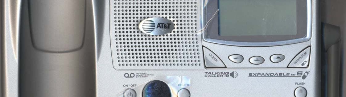
Click to zoom
Application Details
- Equipment Class
- DSS - Part 15 Spread Spectrum Transmitter
- Date of Grant
- Jan 05, 2004
- Application Purpose
- Original Equipment
- Date of Application
- Jan 05, 2004
- Equipment Note
- Cordless Telephone System
- Frequency Range
- 2401.05600000 - 2482.27200000
- Company
- VTech Telecommunications Ltd
- Country
- Hong Kong
Documents & Files
Document Text
Text extracted from the exhibit documents filed with the FCC. Open a document above to read the original.
Users Manual
User Manual (Part 2)2.4 GHz CordlessTelephone/Answ ering System 2525with Caller ID & Call Waiting 1 Table of contents Copyright © 2003 Advanced American Telephones. All Rights Reserved. AT&T and the Globe Design are trademarks of AT&T Corporation., licensed to Advanced American Telephones. User Manual (Part 2)2.4 GHz CordlessTelephone/AnsweringSystem 2525 STOP! See page 7for easy instructions You must install andcharge the battery beforeusing the telephone For customer service or productinformation, visit our web site atwww.telephones.att.comor call 1-800-222-3111 Please also readImportant Product InformationEnclosed in product package Add new handsets to make your phone more versatile (see page 36)Your telephone can accommodate up to four cordless handsets. You can add newhandsets (sold separately) at any time. The handset provided with your telephone is automatically registered as Handset 1. Additional handsets are assigned numbers in the order they are registered (2, 3, 4, etc.). Handset 1 Handset 2 Handset 3 Getting Started Quick reference ...................................2Parts checklist .......................................4Before you begin ..................................5Telephone base installation................6Battery installation & charging ..........7Wall mounting ......................................8Belt clip & optional headset ...............9 Telephone Operation Basic handset operation ...................10Basic base operation .........................11Options during calls ..........................12Intercom calls .....................................13Handset settings.................................14Base settings........................................15Handset clock settings......................16 Phonebooks Handset and base phonebooks.......17New phonebook entries ..................18Phonebook search .............................19To dial, edit or delete a listing ........20 Caller ID Logs How Caller ID works .......................21To review Caller ID logs..................22To dial a Caller ID entry ..................23 Answering System Operation Answering system operation ..........24Day and time announcements ........25Outgoing announcements................26Announce Only mode ......................27Changing feature options .................28Message playback (at base) ..............29Message playback (at handset) ........30Recording and playing memos ........31Message window displays.................32Remote access....................................33 Appendix Display screen status icons..............34Alert tones & indicator lights..........35Adding new handsets ........................36Charging spare batteries ..................37In case of difficulty .............................38INDEX..................................................40Technical specifications ....................42Spare remote access card................43 Answering system controls (see pages 24-33) ON/OFF ..................Press to turn answering system on or off DELETE ..................Press to delete message currently playing TIME SET ................Press to set date and time MENU ......................Press to review or change answering system options CHANGE ................Press to change a menu option RECORD ................Press to record a memo or outgoing announcement 3 Getting Started 2 Getting Started Off/Clear During a call, press to hang up. While using menus, press to cancel anoperation, back up to the previousmenu, or exit the menu display. Quick reference guide Quick reference guide SpeakerPress to activate handset speaker-phone. Press again to hang up.SoftkeysPress a softkey to select a menu item displayed just above the key.Phone/FlashPress to begin a call, then dial a number.During a call, press to receive an incomingcall, if Call Waiting is activated (see page 12). Sound Select Press to customize speaker sound forclear speakerphone conversations (seepage 12). Telephone function keys (see pages 11-15) SOFTKEYS ............Press to select menu item displayed just above the key FLASH ....................During a call, press to receive an incoming call, if Call Waiting is activated VOLUME ................Press to adust speakerphone listening volume MUTE ......................Press to silence microphone; press again to resume SPEAKERPHONE ..Press to answer incoming call or intercom page Handset Telephone Base Answeringsystem controls Telephonefunction keys Swivel antenna fullyupright for best results Xfer/Intercom Press to transfer a call or initiate an intercom conversation (see pages 10 & 13). Redial Log (See page 10) Phonebook (See page 17) Screen menus Item 1 Item 2 Item 3 Press to play messages Press to repeat message.Press twice to hear previous message. Press to skip to next message. Item 1 Item 2 Item 3 HANDSET 1 REDIAL MEM MENU Menus Main MenuCalls Log ................See page 21Play Messages ......See page 30Handset Settings ........See menuSet Time ................See page 16Clock Mode ............See page 16Register ..................See page 36 Handset SettingsRinger Volume ........See page 14Ringer Melody ........See page 14Low Batt Tone ........See page 14Range Tone ............See page 14Keypad Tone ..........See page 14Contrast ..................See page 14Language................See page 14 5 Getting Started 4 Getting Started Before you begin Parts checklist Remember to save your sales receipt and original packaging in case you ever need toship your telephone for warranty service. Check to make sure the telephone packageincludes the following: Telephone base Telephone handset Poweradapter Belt clip Batteries Long line cordShort line cord About Caller Identification Caller ID with Call Waiting features inthis telephone let you see who’s callingbefore you answer the phone, evenwhen you’re on another call. Thesefeatures require services provided byyour local telephone company.Contact your telephone serviceprovider if:• You have both Caller ID …
Text truncated - open the document above for the full version.
Users Manual
User Manual (Part 2)2.4 GHz CordlessSpeakerphone/ Answering System 2555with Caller ID & Call Waiting 1 Table of contents Copyright © 2003 Advanced American Telephones. All Rights Reserved. AT&T and the Globe Design are trademarks of AT&T Corporation., licensed to Advanced American Telephones. User Manual (Part 2)2.4 GHz CordlessSpeakerphone/Answering System 2555 STOP! See page 7for easy instructions You must install andcharge the battery beforeusing the telephone For customer service or productinformation, visit our web site atwww.telephones.att.comor call 1-800-222-3111 Please also readImportant Product InformationEnclosed in product package Add new handsets to make your phone more versatile (see page 36)Your telephone can accommodate up to four cordless handsets. You can add newhandsets (sold separately) at any time. The handset provided with your telephone is automatically registered as Handset 1. Additional handsets are assigned numbers in the order they are registered (2, 3, 4, etc.). Handset 1 Handset 2 Handset 3 Getting Started Quick reference ...................................2Parts checklist .......................................4Before you begin ..................................5Telephone base installation................6Battery installation & charging ..........7Wall mounting ......................................8Belt clip & optional headset ...............9 Telephone Operation Basic handset operation ...................10Basic base operation .........................11Options during calls ..........................12Intercom calls .....................................13Handset settings.................................14Base settings........................................15Handset clock settings......................16 Phonebooks Handset and base phonebooks.......17New phonebook entries ..................18Phonebook search .............................19To dial, edit or delete a listing ........20 Caller ID Logs How Caller ID works .......................21To review Caller ID logs..................22To dial a Caller ID entry ..................23 Answering System Operation Answering system operation ..........24Day and time announcements ........25Outgoing announcements................26Announce Only mode ......................27Changing feature options .................28Message playback (at base) ..............29Message playback (at handset) ........30Recording and playing memos ........31Message window displays.................32Remote access....................................33 Appendix Display screen status icons..............34Alert tones & indicator lights..........35Adding new handsets ........................36Charging spare batteries ..................37In case of difficulty .............................38INDEX..................................................40Technical specifications ....................42Spare remote access card................43 Answering system controls (see pages 24-33) ON/OFF ..................Press to turn answering system on or off DELETE ..................Press to delete message currently playing TIME SET ................Press to set date and time MENU ......................Press to review or change answering system options CHANGE ................Press to change a menu option RECORD ................Press to record a memo or outgoing announcement 3 Getting Started 2 Getting Started Off/Clear During a call, press to hang up. While using menus, press to cancel anoperation, back up to the previousmenu, or exit the menu display. Quick reference guide Quick reference guide SpeakerPress to activate handset speaker-phone. Press again to hang up.SoftkeysPress a softkey to select a menu item displayed just above the key.Phone/FlashPress to begin a call, then dial a number.During a call, press to receive an incomingcall, if Call Waiting is activated (see page 12). Sound Select Press to customize speaker sound forclear speakerphone conversations (seepage 12). Telephone function keys (see pages 11-15) SOFTKEYS ............Press to select menu item displayed just above the key FLASH ....................During a call, press to receive an incoming call, if Call Waiting is activated VOLUME ................Press to adust speakerphone listening volume MUTE ......................Press to silence microphone; press again to resume SPEAKERPHONE ..Press to turn speakerphone on or off (begin or end a call) Handset Base/Speakerphone Answeringsystem controls Telephonefunction keys Swivel antenna fullyupright for best results Xfer/Intercom Press to transfer a call or initiate an intercom conversation (see pages 10 & 13). Redial Log (See page 10) Phonebook (See page 17) Screen menus Item 1 Item 2 Item 3 Press to play messages Press to repeat message.Press twice to hear previous message. Press to skip to next message. Item 1 Item 2 Item 3 HANDSET 1 REDIAL MEM MENU Menus Main MenuCalls Log ................See page 21Play Messages ......See page 30Handset Settings ........See menuSet Time ................See page 16Clock Mode ............See page 16Register ..................See page 36 Handset SettingsRinger Volume ........See page 14Ringer Melody ........See page 14Keypad Tone ..........See page 14Tone/Pulse..............See page 14Contrast ..................See page 14Language................See page 14 5 Getting Started 4 Getting Started Before you begin Parts checklist Remember to save your sales receipt and original packaging in case you ever need toship your telephone for warranty service. Check to make sure the telephone packageincludes the following: Telephone base Telephone handset Poweradapter Belt clip Batteries Long line cordShort line cord About Caller Identification Caller ID with Call Waiting features inthis telephone let you see who’s callingbefore you answer the phone, evenwhen you’re on another call. Thesefeatures require services provided byyour local telephone company.Contact your telephone serviceprovider if:• You have both Caller ID and Call W…
Text truncated - open the document above for the full version.
Users Manual
IMPORTANT PRODUCT INFORMATION Safety Information This symbol is to alert you to important operating or servicing instructions that may appear in this user’s manual. Always follow basic safety precautions when using this product to reduce the risk of injury, fire, or electric shock. 1Read and understand all instructions in the user’s manual. Observe all markings on the product. 2Avoid using a telephone during a thunderstorm. There may be a slight chance of electric shock from lightning. 3Do not use a telephone in the vicinity of a gas leak. If you suspect a gas leak, report it immediately, but use a telephone away from the area where gas is leaking. If this product is a cordless model, make sure the base is also away from the area. 4Do not use this product near water, or when you are wet. For example, do not use it in a wet basement or shower, or next to a swimming pool, bathtub, kitchen sink, or laundry tub. Do not use liquids or aerosol sprays for cleaning. If the product comes in contact with any liquids, unplug any line or power cord immediately. Do not plug the product back in until it has dried thoroughly. 5Install this product in a protected location where no one can trip over any line or power cords. Protect cords from damage or abrasion. 6If this product does not operate normally, read “In Case of Difficulty” in the user’s manual. If you cannot solve the problem, or if the product is damaged, refer to the Limited Warranty. Do not open this product except as may be directed in your user’s manual. Opening the product or reassembling it incorrectly may expose you to hazardous voltages or other risks. Part 1 (Continued) © 2001 Advanced American Telephones. All Rights Reserved. AT&T and the Globe Design are trademarks of AT&T Corp., licensed to Advanced American Telephones. 2 7If this product has user-replaceable batteries, replace batteries only as described in your user’s manual. Do not burn or puncture batteries — they contain caustic chemicals. 8If this product has a three-prong (grounding) plug or a polarized plug with one wide prong, it may not fit in non-polarized outlets. Do not defeat the purpose of these plugs. If they do not fit in your outlet, the outlet should be replaced by an electrician. CAUTION:Use only the power adapter provided with this product. To obtain a replacement, call 1 800 222–3111. SAVE THESE INSTRUCTIONS Especially About Cordless Telephones Privacy: The same features that make a cordless phone convenient create some limitations. Telephone calls are transmitted between the base and the handset by radio waves, so there is a possibility that your cordless phone conversations could be intercepted by radio receiving equipment within range of the cordless handset. For this reason, you should not think of cordless phone conversations as being as private as those on corded phones. Electrical Power:The base unit of this cordless telephone must be connected to a working electrical outlet. The electrical outlet should not be controlled by a wall switch. Calls cannot be made from the handset if the base unit is unplugged or switched off, or if the electrical power is interrupted. Potential TV Interference:Some cordless telephones operate at frequencies that may cause interference to TVs and VCRs. To minimize or prevent such interference, do not place the base unit of the cordless telephone near or on top of a TV or VCR. If interference is experienced, moving the cordless telephone farther away from the TV or VCR will often reduce or eliminate the interference. (Applies to 25-channel cordless phones only.) Rechargeable Batteries:This product contains either Nickel- Cadmium or Nickel-Metal Hydride rechargeable batteries. Exercise care in handling batteries in order not to short the battery with conducting material such as rings, bracelets, and keys. The battery or conductor may overheat and cause harm. Observe proper polarity between the battery and the battery charger. 3 Nickel-Cadmium Rechargeable Batteries:Must be recycled or disposed of properly. Do not dispose of in household garbage. Do not burn or puncture. Like other batteries of this type, if burned or punctured, they could release caustic material which could cause injury. The RBRC ™ Seal means that the manufacturer is voluntarily participating in an industry program to collect and recycle Nickel-Cadmium rechargeable batteries when taken out of service within the United States. These batteries may be taken to a participating local retailer of replacement batteries or recycling center. Or you may call 1 800 8BATTERY for locations accepting spent Nickel-Cadmium Batteries. Nickel-Metal Hydride Rechargeable Batteries:Dispose of these batteries in a safe manner. Do not burn or puncture. Like other batteries of this type, if burned or punctured, they could release caustic material which could cause injury. Precautions for Users of Implanted Cardiac Pacemakers Cardiac Pacemakers (applies only to 900 MHz Digital Cordless Telephones): Wireless Technology Research, LLC (WTR), an independent research entity, led a multidisciplinary evaluation of the interference between portable wireless telephones and implanted cardiac pacemakers. Supported by the U.S. Food and Drug Administration, WTR had recommended to physicians that: PACEMAKER PATIENTS •Should keep wireless phones at least six inches from the pacemaker •Should NOTplace wireless phones directly over the pacemaker, such as in a breast pocket, when it is turned ON •Should use the wireless phone at the ear opposite the pacemaker WTR’s evaluation did not identify any risk to bystanders with pacemakers from other persons using wireless phones. 4 Especially About Telephone Answering Systems Two-Way Recording:This unit does not sound warning beeps to let the other party know that the call is being recorded. To ensure that you are in compliance with any federal or state regulations regarding recording a telephone call, you should start the recording process and then inform …
Text truncated - open the document above for the full version.
Cover Letter(s)
December 11, 2003 Federal Communications Commission Authorization and Evaluation Division Confidentiality Request regarding application for certification of FCC ID: EW780-5425-00 Pursuant to Sections 0.457 and 0.459 of the Commission’s Rules, we hereby request confidential treatment of information accompanying this application as outlined below: (1) Theory of Operation (2) Wireless System Description (3) Schematics (4) Block Diagrams (5) Part Lists The above materials contain trade secrets and proprietary information not customarily released to the public. The public disclosure of these materials may be harmful to the applicant and provide unjustified benefits to its competitors. The applicant understands that pursuant to Section 0.457 of the Rules, disclosure of this application and all accompanying documentation will not be made before the date of the Grant for this application. Sincerely, Joseph Poon Regulatory Compliance Manager
External Photos
AT&T E2525 Base Cosmetic AT&T E2525 Base Cosmetic AT&T E2555 Base Cosmetic AT&T E2555 Base Cosmetic
External Photos
AT&T E2525/E2555 Handset Cosmetic AT&T E2525/E2555 Handset Cosmetic
ID Label/Location Info
EW780-5425-00 US: EW7W401B80-542500 0.1B IC: 1135A-80542500 EW780-5425-00 IC: 1135A-80542500 EW7 80 - 5 42 5 - 00 IC: 1135A-80542500 IC: 1135A-80542500 US: EW7W401B80-542500 EW780-5425-00 0.1B
ID Label/Location Info
EW780-5425-00 US: EW7W401B80-542500 0.1B IC: 1135A-80542500 EW780-5425-00 IC: 1135A-80542500 EW7 80 - 5 42 5 - 00 IC: 1135A-80542500 IC: 1135A-80542500 US: EW7W401B80-542500 EW780-5425-00 0.1B MODEL E2555/E2655B MODEL E2555/E2655B
Internal Photos
AT&T E2525/E2555 Base PCB AT&T E2525/E2555 Base PCB AT&T E2525/E2555 Base PCB AT&T E2525/E2555 Base PCB AT&T E2525/E2555 Base PCB
Internal Photos
AT&T E2525/E2555 Handset PCB AT&T E2525/E2555 Handset PCB AT&T E2525/E2555 Handset PCB
RF Exposure Info
Prediction of MPE limit at a given distance Equation from page 18 of OET Bulletin 65, Edition 97-01where: S = power density P = power input to the antennaG = power gain of the antenna in the direction of interest relative to an isotropic radiatorR = distance to the center of radiation of the antenna Maximum peak output power a antenna input terminal: 20.50 (dBm) Maximum peak output power at antenna input terminal: 112 (mW) Antenna gain(typical): 2.5 (dBi) Maximum antenna gain: 1 . 7782794 (numeric) Prediction distance: 20 (cm) Prediction frequency: 24 00 (MHz) MPE limit for uncontrolled exposure at prediction frequency: 1 (mW/cm^2) Power density at prediction frequency: 0 . 039623 (mW/cm^2) Maximum allowable antenna gain: 16.520518 (dBi) Margin of Compliance at 20cm = 14 . 0 dB 2 4 R PG S π =
RF Exposure Info
VTech Engineering Canada Ltd. 200 – 7671 Alderbridge Way, Richmond, B.C. Canada V6X 1Z9 Tel: (604) 273-5131 Fax: (604) 276-9137 Radio Frequency Exposure Information For AT&T E2525 / E2555 Cordless Handset Handset (Tx / Rx: 2.4GHz band) Readings from test report : (1) Max. Output Power = 122.6 mW (20.9 dBm) (2) Duty cycle – 1ms / 10ms = 10% (measured in single slot transmission) Under the worst environment with interference, dual slot diversity gives the max. duty cycle on the handset Tx (ie. 10% x2 or 20%) Hence, taking the max. power output & max. duty cycle, the average effective output power is : 122.6 mW x 20% = 24.52 mW Conclusion : The average effective output power is lower than the low threshold level (25mW) of portable device that operates less than 20cm from a person’s body. Hence, there is no RF exposure concerns on handset.
Test Report
Master: PT15C-FHT Date: February 7, 2002 Test Report: 3W07663, Issue 2 Applicant: VTech Engineering Canada Ltd. Suite 200 – 7671 Alderbridge Way Richmond, B.C., Canada V6X 1Z9 Equipment Under Test: E2525 & E2555 (EUT) In Accordance With: FCC Part 15, Subpart C Frequency Hopping Transmitters 2400 - 2483.5 MHz Tested By: Nemko Canada Inc. 303 River Road, R.R. 5 Ottawa, Ontario K1V 1H2 Authorized By: Glen Westwell, Wireless Technologist Date: 12 December 2003 Total Number of Pages: 48 Nemko Canada Inc. FCC PART 15, SUBPART C FREQUENCY HOPPING TRANSMITTERS PROJECT NO.:3W07663, ISSUE 2 EQUIPMENT: E2525 & E2555 Page 2 of 47 Table of Contents Section 1. Summary of Test Results ...................................................................................3 Section 2. General Equipment Specification......................................................................5 Section 3. Powerline Conducted Emissions........................................................................6 Section 4. Channel Separation ..........................................................................................12 Section 5. Number of Hopping Channels .........................................................................14 Section 6. Time of Occupancy ...........................................................................................18 Section 7. Occupied Bandwidth ........................................................................................23 Section 8. Peak Power Output...........................................................................................30 Section 9. Spurious Emissions (Radiated).........................................................................32 Section 10. Block Diagrams ..................................................................................................46 Section 11. Test Equipment List ..........................................................................................48 Nemko Canada Inc. FCC PART 15, SUBPART C FREQUENCY HOPPING TRANSMITTERS PROJECT NO.:3W07663, ISSUE 2 EQUIPMENT: E2525 & E2555 Page 3 of 47 Section 1. Summary of Test Results General All measurements are traceable to national standards. These tests were conducted on a sample of the equipment for the purpose of demonstrating compliance with Part 15, Subpart C, Paragraph 15.247 for Frequency Hopping Spread Spectrum devices. Radiated tests were conducted is accordance with ANSI C63.4-1992. Radiated emissions are made on an open area test site. A description of the test facility is on file with the FCC. THIS TEST REPORT RELATES ONLY TO THE ITEM(S) TESTED. THE FOLLOWING DEVIATIONS FROM, ADDITIONS TO, OR EXCLUSIONS FROM THE TEST SPECIFICATIONS HAVE BEEN MADE. NONE TESTED BY: _______________________________ DATE: 12 December 2003 Kevin Carr, EMC/EMI/Wireless Specialist Nemko Canada Inc. authorizes the above named company to reproduce this report provided it is reproduced in its entirety and for use by the company’s employees only. Any use which a third party makes of this report, or any reliance on or decisions to be made based on it, are the responsibility of such third parties. Nemko Canada Inc. accepts no responsibility for damages, if any, suffered by any third party as a result of decisions made or actions based on this report. This report applies only to the items tested. Nemko Canada Inc. FCC PART 15, SUBPART C FREQUENCY HOPPING TRANSMITTERS PROJECT NO.:3W07663, ISSUE 2 EQUIPMENT: E2525 & E2555 Page 4 of 48 Summary Of Test Data Name Of Test Para. No. Result Powerline Conducted Emissions 15.207(a) Complies Channel Separation 15.247(a)(1) Complies Time of Occupancy 15.247(a)(1)(iii) Complies 20 dB Occupied Bandwidth 15.247(a)(1) Complies Number of Hopping Channels 15.247(a)(1)(iii) Complies Peak Power Output 15.247(b)(1) Complies Spurious Emissions (Antenna Conducted) 15.247(c) NA Spurious Emissions (Radiated) 15.247(c) Complies Footnotes For N/A’s: No Access Port Additional Note: The handset & base pair are using the same RF module, so only one handset & one base. Model E2555 was selected due to it’s extra keypad circuitry on the base unit. Test Conditions: Indoor Temperature: 22°C Humidity: 55% Outdoor Temperature: 7°C Humidity: 54% Nemko Canada Inc. FCC PART 15, SUBPART C FREQUENCY HOPPING TRANSMITTERS PROJECT NO.:3W07663, ISSUE 2 EQUIPMENT: E2525 & E2555 Page 5 of 48 Section 2. General Equipment Specification Manufacturer: VTech (Dongguan) Electronics and Communications Ltd. Model No.: E2525 & E2555 Serial No.: FP:PA22, PP: PA07 Date Received In Laboratory: 24 Nov. 2003 Nemko Identification No.: 2 & 3 Frequency Range: 2401.056 – 2482.272MHz Tunable Bands: 1 Number of Channels: 17 Min. Channel Spacing: 860kHz Emissions Designator: PP: 683kF1D FP: 642kF1D User Frequency Adjustment: None Rated Output Power: PP: 0.1226W, 20.9dBm FP: 0.1114W, 20.5dBm Nemko Canada Inc. FCC PART 15, SUBPART C FREQUENCY HOPPING TRANSMITTERS PROJECT NO.:3W07663, ISSUE 2 EQUIPMENT: E2525 & E2555 Page 6 of 48 Section 3. Powerline Conducted Emissions Para. No.: 15.207 (a) Test Performed By: Kevin Carr Date of Test: 24 Nov. 2003 Test Results: Complies Measurement Data: See attached graph(s). Nemko Canada Inc. FCC PART 15, SUBPART C FREQUENCY HOPPING TRANSMITTERS PROJECT NO.:3W07663, ISSUE 2 EQUIPMENT: E2525 & E2555 Page 7 of 48 Powerline Conducted Emission Plots Nemko Canada Inc. FCC PART 15, SUBPART C FREQUENCY HOPPING TRANSMITTERS PROJECT NO.:3W07663, ISSUE 2 EQUIPMENT: E2525 & E2555 Page 8 of 48 Nemko Canada Inc. FCC PART 15, SUBPART C FREQUENCY HOPPING TRANSMITTERS PROJECT NO.:3W07663, ISSUE 2 EQUIPMENT: E2525 & E2555 Page 9 of 48 Nemko Canada Inc. FCC PART 15, SUBPART C FREQUENCY HOPPING TRANSMITTERS PROJECT NO.:3W07663, ISSUE 2 EQUIPMENT: E2525 & E2555 Page 10 of 48 Conducted Disturbance at Mains Port Test Data, continued: Port under test: Test Voltage: Conductor Frequency (MHz) Detector Level (dBμV) LISN Loss (dB) Cable Loss (dB) Result (dBμV) Limit (dBμV) Margin (dB) Quasi-Peak 37.5…
Text truncated - open the document above for the full version.
Test Setup Photos
Nemko Canada Inc. FCC PART 15, SUBPART C FREQUENCY HOPPING TRANSMITTERS PROJECT NO.:3W07663, ISSUE 2 EQUIPMENT: E2525 & E2555 Page 44 of 48 Set-up Photo: Nemko Canada Inc. FCC PART 15, SUBPART C FREQUENCY HOPPING TRANSMITTERS PROJECT NO.:3W07663, ISSUE 2 EQUIPMENT: E2525 & E2555 Page 45 of 48
Contact Information
Applicant
Michael Tsui(Approbation Supervisor)
Test Firm
Nemko Canada Inc.Stuart Beck
Technical Specifications
| # | Rule Parts | Frequency Range | Power Output |
|---|---|---|---|
| 2 | 15C | 2.40 GHz - 2.48 GHz | 111.40 mW |
Other Applications from VTech Telecommunications Ltd

EW780-2531-01
Sep 12, 2024Video Baby Monitor
Equipment Class
DSS - Part 15 Spread Spectrum Transmitter
EW780-2531-00
Sep 12, 2024Video Baby Monitor
Equipment Class
DXX - Part 15 Low Power Communication Device Transmitter
EW780-2792-00A
Sep 09, 2024Video Baby Monitor
Equipment Class
DSS - Part 15 Spread Spectrum Transmitter
EW780-H0HQ-13
Aug 20, 2024SIP cordless hotel phone
Equipment Class
PUB - Part 15 Unlicensed PCS Base Station
EW780-2365-00A
Aug 19, 2024Video Baby Monitor
Equipment Class
DSS - Part 15 Spread Spectrum Transmitter