EW780-5744-10Cordless Telephone Base Transceiver
VTech Telecommunications Ltd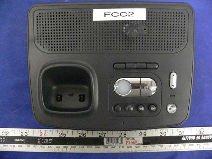
Click to zoom
Application Details
- Equipment Class
- DTS - Digital Transmission System
- Date of Grant
- Dec 21, 2005
- Application Purpose
- Original Equipment
- Date of Application
- Dec 21, 2005
- Equipment Note
- Cordless Telephone Base Transceiver
- Frequency Range
- 2400.90000000 - 2405.10000000
- Company
- VTech Telecommunications Ltd
- Country
- Hong Kong
Documents & Files
Document Text
Text extracted from the exhibit documents filed with the FCC. Open a document above to read the original.
Users Manual
36 Appendix FCC Part 68 and ACTA This equipment complies with Part 68 of the FCC rules and with technical require- ments adopted by the Administrative Council for Terminal Attachments (ACTA). The label on the back or bottom of this equipment contains, among other things, a product identifier in the format US: AAAEQ##TXXXX. This identifier must be provided to your local telephone company upon request. The plug and jack used to connect this equipment to premises wiring and the tele- phone network must comply with applicable Part 68 rules and technical requirements adopted by ACTA. A compliant telephone cord and modular plug is provided with this product. It is designed to be connected to a compatible modular jack that is also com- pliant. An RJ11 jack should normally be used for connecting to a single line and an RJ14 jack for two lines. See Installation Instructions in the user’s manual. The Ringer Equivalence Number (REN) is used to determine how many devices you may connect to your telephone line and still have them ring when you are called. The REN for this product is encoded as the 6th and 7th characters following the US: in the product identifier (e.g., if ## is 03, the REN is 0.3). In most, but not all areas, the sum of all RENs should be five (5.0) or less. For more information, please contact your localtelephone company. This equipment may not be used with Party Lines. If you have specially wired alarm dial- ing equipment connected to your telephone line, ensure the connection of this equip- ment does not disable your alarm equipment. If you have questions about what will disable alarm equipment, consult your telephone company or a qualified installer. If this equipment is malfunctioning, it must be unplugged from the modular jack until the problem has been corrected. Repairs to this telephone equipment can only be made by the manufacturer or its authorized agents. For repair procedures, follow the instructions outlined under the Limited Warranty. If this equipment is causing harm to the telephone network, the telephone com- pany may temporarily discontinue your telephone service. The telephone company is required to notify you before interrupting service. If advance notice is not practical, you will be notified as soon as possible. You will be given the opportunity to correct the problem and the telephone company is required to inform you of your right to file a complaint with the FCC. Your telephone company may make changes in its facilities, equipment, operation, or procedures that could affect the proper functioning of this product. The telephone company is required to notify you if such changes are planned. If this product is equipped with a corded or cordless handset, it is hearing aid compat- ible. 37 Appendix FCC Part 15 If this product has memory dialing locations, you may choose to store emergency telephone numbers (e.g., police, fire, medical) in these locations. If you do store or test emergency numbers, please: • Remain on the line and briefly explain the reason for the call before hanging up. • Perform such activities in off-peak hours, such as early morning or late evening. This equipment has been tested and found to comply with the requirements for a Class B digital device under Part 15 of the Federal Communications Commission (FCC) rules. These requirements are intended to provide reasonable protection against harmful interference in a residential installation. This equipment generates, uses and can radiate radio frequency energy and, if not installed and used in accordance with the instructions, may cause harmful interference to radio communications. However, there is no guarantee that interference will not occur in a particular installation. If this equip- ment does cause harmful interference to radio or television reception, which can be determined by turning the equipment off and on, the user is encouraged to try to cor- rect the interference by one or more of the following measures: • Reorient or relocate the receiving antenna. • Increase the separation between the equipment and receiver. • Connect the equipment into an outlet on a circuit different from that to which the receiver is connected. • Consult the dealer or an experienced radio/TV technician for help. Changes or modifications to this equipment not expressly approved by the party responsible for compliance could void the user’s authority to operate the equipment. To ensure safety of users, the FCC has established criteria for the amount of radio frequency energy that can be safely absorbed by a user or bystander according to the intended usage of the product. This product has been tested and found to comply with the FCC criteria. The handset may be safely held against the ear of the user. The base unit shall be installed and used such that parts of the user’s body other than the hands are maintained at a distance of approximately 20 cm (8 inches) or more. If you choose to use a clipping device, please make sure to only use the supplied AT&T belt clip.
Users Manual
CHAN MUTE REDIAL User Manual 2.4 GHz Cordless Telephone E2116 with Caller ID & Call Waiting Congratulations on your purchase of this AT&T product. Before using this telephone system, please read Important Safety Instructions in the Appendix of this manual. NEED HELP? Our representatives are here to help you with any questions concerning the operation of this product, available accessories, or any other related issues. Call Toll Free 1 (800) 222-3111 In Canada, Call 1 (866) 288-4268 or visit our website at www.telephones.att.com Model No.: AT&T E2116 Product Name: 2.4 GHz Cordless Telephone Serial No.: SN: (found at the bottom of the base unit) Purchase Date: Dealer: Depending on your service subscription, you may see the caller’s number, or the caller’s name and number. This product can provide information only if both you and the caller are in areas offering Caller ID service, and if both telephone companies use compatible equipment. The time and date are sent by the service provider along with the call information. Information about Caller ID with Call Waiting Copyright © 2005 Advanced American Telephones. All Rights Reserved. AT&T and the Globe Design are trademarks of AT&T Corp., licensed to Advanced American Telephones. This product has a Caller ID with Call Waiting feature that works with service from your local phone service provider. Caller ID with Call Waiting lets you see who’s calling before you answer the phone, even when you’re on another call. You may need to change your phone service to use this feature. Contact your phone service provider if: • You have both Caller ID and Call Waiting, but as separate ser- vices (you may need combined service). • You have only Caller ID service, or only Call Waiting service. • You don’t subscribe to any Caller ID or Call Waiting services. You can use this product with regular Caller ID service, you can use this product’s other features without subscribing to either Caller ID or combined Caller ID with Call Waiting service. There are fees for Caller ID services, and they may not be available in all areas. IMPORTANT Copyright © 2005 Advanced American Telephones. All Rights Reserved. AT&T and the Globe Design are trademarks of AT&T Corp., licensed to Advanced American Telephones. STOP! See page 7 for easy instructions. You must install and charge the battery before using the telephone. Please also read Important Product Information on page 32. For customer service or product information, visit our web site at www.telephones.att.com or call 1-800-222-3111. In Canada, call 1-866-288-4268. CAUTION: To reduce the risk of fire or injury to persons or damage to the telephone, read and follow these instructions carefully: • Use only replacement battery model 3301(Part number 80-5071-00-00 or AT&T SKU 23403). • Do not dispose of the battery in a fire, it could explode. Check with local codes for special disposal instructions. • Do not open or mutilate the battery. Released electrolyte is corrosive and may cause damage to the eyes or skin. It may be toxic if swallowed. • Exercise care in handling batteries in order not to create a short circuit with conducting materials such as rings, bracelets, and keys. The battery or conduc- tor may overheat and cause harm. • Charge the battery provided with or identified for use with this product only in accordance with the instructions and limitations specified in this manual. • Observe proper polarity orientation between the battery and battery charger. Do not disassemble your telephone. There are no user-serviceable parts inside. Refer for servicing to qualified service personnel. 1 CHAN MUTE REDIAL User Manual 2.4 GHz Cordless Telephone E2116 with Caller ID & Call Waiting Getting Started Quick reference guide ........................ 2 Parts checklist ...................................... 4 Before you begin .................................. 5 Telephone base installation ................ 6 Battery installation & charging .......... 7 Wall mounting ...................................... 8 Belt clip & optional headset .............. 9 Telephone Operation Handset Operation ...........................10 Handset Settings ................................12 Base Operation ..................................13 Messages Waiting ...............................14 Speed Dial ...........................................16 Directory Store/Edit an entry ............................19 Delete/Move an entry to Speed Dial ................................................................20 Dial a number from the Directory ...20 Caller ID Log How Caller ID works .......................21 To review the call log ........................23 Appendix Troubleshooting .................................28 Important Product Information ..... 33 Save /these Instructionsn ................. 34 FCC Part 68 and ACTA .... ...............36 FCC Part 15 ....................................... 37 Limited Warranty .............................. 38 Technical Specifi cations .................... 41 Table of contents 2 CHAN MUTE REDIAL OFF While on a call, press to temporarily mute the ringer. While using menus, press to cancel an operation, back up, or exit the menu display. When ringing, press to temporarily mute the ringer. Redial/Pause Press to view redial memory. While entering numbers, press and hold to insert a dialing pause. CID While on a call, press to lower the volume. A double beep will sound when you reach the lowest setting. While the phone is not in use, press to display caller ID information. While entering names or numbers into memory, press to delete last character entered. SPEAKER Press to activate handset speakerphone. Press again to resume normal handset use (earpiece). DIR While on a call, press to increase the volume. A double beep will sound when you reach the highest setting. While the phone is not in use, press to display directory entries. While entering names or numbers, press to add a space. PHONE/FLASH Press to make or answe…
Text truncated - open the document above for the full version.
Cover Letter(s)
Nov 16, 2005 Equipment Authorization Division Federal Communications Commission 7435 Oakland Mills Road Columbia, MD 21046 FCC ID: EW780-5744-10 (Base) EW780-5744-11 (Handset) Product Name: AT&T E2116 / E2126 Request for Confidentiality Pursuant to Sections 0.457 and 0.459 of the commissions rules, we hereby request that the following documents (list no# 1 to 4) be held confidential: (1) Theory of Operation (2) Block Diagrams (3) Schematics We also request that the FCC mark the below documents (list no# 5 to 7) as "Temporary Confidential" as outlined in Public Notice DA 04-1705, dated June 15, 2004. This provision will give Vtech temporary confidentiality prior to product launch. (4) External Photos (5) Internal Photos (6) Users Manual These materials contain trade secrets and proprietary information and are not customarily released to the public. The public disclosure of this information might be harmful to the company and provide unjustified benefits to our competitors. Dated this 17th Day of November 20 05 By: Joseph Poon Signature Printed Title: Regulatory Compliance Manager On behalf of : VTech Telecommunications Canada Ltd. Telephone: (604) 273-5131
External Photos
VTech Telecommunications Ltd. FCC ID: EW780-5744-10 Report # R0511071(B)Exhibits FCC Part 15.247 Test Report EXHIBIT C - EUT PHOTOGRAPHS E2116: EUT – Front View E2116: EUT – Rear View
ID Label/Location Info
EXHIBIT A - FCC ID LABEL INFORMATION Proposed FCC ID Label Proposed Label Location on EUT Back View of EUT/FCC ID Label FCC ID: EW780-5744-10 This device complies with Part 15 o the FCC Rules. Operation is subject to the following two conditions: (1) this device may not cause harmful interference, and (2) this device must accept any interference received, including interference that may cause undesired operation. 2.1875" 1.0" Model: E2116 Model: E2126
Internal Photos
VTech Telecommunications Ltd. FCC ID: EW780-5744-10 Report # R0511071(B)Exhibits FCC Part 15.247 Test Report E2116: EUT –Uncovered View E2116: EUT –Display board View (1) VTech Telecommunications Ltd. FCC ID: EW780-5744-10 Report # R0511071(B)Exhibits FCC Part 15.247 Test Report E2116: EUT –Display board View (2) E2116: EUT – Main board PCB View (1) VTech Telecommunications Ltd. FCC ID: EW780-5744-10 Report # R0511071(B)Exhibits FCC Part 15.247 Test Report E2116: EUT – Main board View (2) E2116: EUT-RF board View (1) VTech Telecommunications Ltd. FCC ID: EW780-5744-10 Report # R0511071(B)Exhibits FCC Part 15.247 Test Report E2116: EUT-RF board View (2) E2116: EUT – Adapter View VTech Telecommunications Ltd. FCC ID: EW780-5744-10 Report # R0511071(B)Exhibits FCC Part 15.247 Test Report E2126: EUT – Front View E2126: EUT – Rear View VTech Telecommunications Ltd. FCC ID: EW780-5744-10 Report # R0511071(B)Exhibits FCC Part 15.247 Test Report E2126: EUT – Cover off View E2126: EUT – Main board PCB View VTech Telecommunications Ltd. FCC ID: EW780-5744-10 Report # R0511071(B)Exhibits FCC Part 15.247 Test Report E2126: EUT – RF board View (1) E2126: EUT – RF board View (2)
RF Exposure Info
§1.1307(b)(1) & §2.1091 - RF EXPOSURE According to §15.247(b)(5) and §1.1307(b)(1), systems operating under the provisions of this section shall be operated in a manner that ensures that the public is not exposed to radio frequency energy level in excess of the Commission’s guidelines. According to §1.1310 and §2.1091 RF exposure is calculated. Limits for General Population/Uncontrolled Exposure Frequency Range (MHz) Electric Field Strength (V/m) Magnetic Field Strength (A/m) Power Density (mW/cm 2 ) Averaging Time (minute) Limits for General Population/Uncontrolled Exposure 0.3-1.34 614 1.63 *(100) 30 1.34-30 824/f 2.19/f *(180/f 2 ) 30 30-300 27.5 0.073 0.2 30 300-1500 / / f/1500 30 1500-100,000 / / 1.0 30 f = frequency in MHz * = Plane-wave equivalent power density MPE Prediction Predication of MPE limit at a given distance Equation from page 18 of OET Bulletin 65, Edition 97-01 S = PG/4πR² Where: S = power density P = power input to antenna G = power gain of the antenna in the direction of interest relative to an isotropic radiator R = distance to the center of radiation of the antenna Maximum peak output power at antenna input terminal: 13.21(dBm ) Maximum peak output power at antenna input terminal: 20.94 (mW) Prediction distance: 20 (cm) Predication frequency: 2400 (MHz) Antenna Gain (typical): 0 (dBi) antenna gain: 1 (numeric) Power density at predication frequency at 20 cm: 0.004(mW/cm 2 ) MPE limit for uncontrolled exposure at prediction frequency: 1.0 (mW/cm 2 ) Test Result The EUT is a mobile device. The power density level at 20 cm is 0.004mW/cm², which is below the uncontrolled exposure limit of 1.0mW/cm² at 2400 MHz.
Test Report
Note: The test report is specially limited to the above company and this particular sample only. It may not be duplicated without prior written consent of Bay Area Compliance Laboratory Corporation. This report must not be used by the client to claim product certification, approval, or endorsement by NVLAP, NIST or any agency of the US Government. FCC PART 15.247 EMI MEASUREMENT AND TEST REPORT For VTech Telecommunications Ltd. 23/F Tai Ping Ind Center Block 1, 57 Ting Kok Rd, Tai Po NT FCC ID: EW780-5744-10 This Report Concerns: Original Report Equipment Type: 900MHZ / 2.4 GHz Cordless Phone Test Engineer: Daniel Deng Report No.: R0511071(B)-b Report Date: 2005-12-20 Reviewed By: Richard Lee Prepared By: Bay Area Compliance Laboratory Corporation (BACL) 230 Commercial Street Sunnyvale, CA 94085 Tel: (408) 732-9162 Fax: (408) 732 9164 VTech Telecommunications Ltd. FCC ID: EW780-5744-10 Report # R0511071(B)Rpt Page 2 of 38 FCC Part 15.247 Test Report TABLE OF CONTENTS GENERAL INFORMATION.......................................................................................................................................4 PRODUCT DESCRIPTION FOR EQUIPMENT UNDER TEST (EUT) ....................................................................................4 OBJECTIVE...................................................................................................................................................................4 RELATED SUBMITTAL(S)/GRANT(S).............................................................................................................................4 TEST METHODOLOGY..................................................................................................................................................4 TEST FACILITY.............................................................................................................................................................4 SYSTEM TEST CONFIGURATION ..........................................................................................................................6 JUSTIFICATION.............................................................................................................................................................6 EUT EXERCISE SOFTWARE..........................................................................................................................................6 SPECIAL ACCESSORIES.................................................................................................................................................6 SCHEMATICS / BLOCK DIAGRAM.................................................................................................................................6 EQUIPMENT MODIFICATIONS.......................................................................................................................................6 POWER SUPPLY............................................................................................................................................................6 INTERFACE PORTS AND CABLING.................................................................................................................................6 CONFIGURATION OF TEST SYSTEM..............................................................................................................................7 TEST SETUP BLOCK DIAGRAM.....................................................................................................................................7 SUMMARY OF TEST RESULTS ...............................................................................................................................8 §1.1307(B)(1) & §2.1091 - RF EXPOSURE.................................................................................................................9 §15.203 - ANTENNA REQUIREMENT....................................................................................................................10 STANDARD APPLICABLE............................................................................................................................................10 §15.207 (A)- CONDUCTED EMISSION...................................................................................................................11 MEASUREMENT UNCERTAINTY..................................................................................................................................11 TEST SETUP................................................................................................................................................................11 RECEIVER SETUP........................................................................................................................................................11 TEST EQUIPMENT LIST AND DETAILS.........................................................................................................................11 TEST PROCEDURE......................................................................................................................................................11 ENVIRONMENTAL CONDITIONS..................................................................................................................................11 SUMMARY OF TEST RESULTS.....................................................................................................................................12 CONDUCTED EMISSIONS TEST DATA.........................................................................................................................12 PLOT OF CONDUCTED EMISSIONS TEST DATA...........................................................................................................12 §2.1051 & §15.247(C) - SPURIOUS EMISSIONS AT ANTENNA TERMINALS................................................15 STANDARD APPLICABLE......................................................................................................................…
Text truncated - open the document above for the full version.
Test Setup Photos
VTech Telecommunications Ltd. FCC ID: EW780-5744-10 Report # R0511071(B)Exhibits FCC Part 15.247 Test Report EXHIBIT B - TEST SETUP PHOTOGRAPHS E2116: Conducted Emission - Front View E2116: Conducted Emission –Side View VTech Telecommunications Ltd. FCC ID: EW780-5744-10 Report # R0511071(B)Exhibits FCC Part 15.247 Test Report E2116: Radiated Emission - Front View E2116: Radiated Emission - Rear View VTech Telecommunications Ltd. FCC ID: EW780-5744-10 Report # R0511071(B)Exhibits FCC Part 15.247 Test Report E2126: Radiated Emission - Front View E2126: Radiated Emission - Rear View
Contact Information
Applicant
Michael Tsui(Approbation Supervisor)
Test Firm
Bay Area Compliance LaboratoryJohn Chan
Technical Specifications
| # | Rule Parts | Frequency Range | Power Output |
|---|---|---|---|
| 1 | 15C | 2.40 GHz - 2.41 GHz | 20.94 mW |
Other Applications from VTech Telecommunications Ltd

EW780-2531-01
Sep 12, 2024Video Baby Monitor
Equipment Class
DSS - Part 15 Spread Spectrum Transmitter
EW780-2531-00
Sep 12, 2024Video Baby Monitor
Equipment Class
DXX - Part 15 Low Power Communication Device Transmitter
EW780-2792-00A
Sep 09, 2024Video Baby Monitor
Equipment Class
DSS - Part 15 Spread Spectrum Transmitter
EW780-H0HQ-13
Aug 20, 2024SIP cordless hotel phone
Equipment Class
PUB - Part 15 Unlicensed PCS Base Station
EW780-2365-00A
Aug 19, 2024Video Baby Monitor
Equipment Class
DSS - Part 15 Spread Spectrum Transmitter