EW780-6044-01Cordless Telephone - Base
VTech Telecommunications Ltd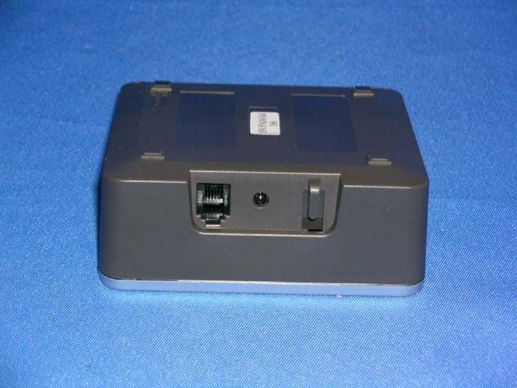
Click to zoom
Application Details
- Equipment Class
- PUB - Part 15 Unlicensed PCS Base Station
- Date of Grant
- Nov 13, 2006
- Application Purpose
- Original Equipment
- Date of Application
- Nov 13, 2006
- Equipment Note
- Cordless Telephone - Base
- Frequency Range
- 1921.53600000 - 1928.44800000
- Company
- VTech Telecommunications Ltd
- Country
- Hong Kong
Documents & Files
Document Text
Text extracted from the exhibit documents filed with the FCC. Open a document above to read the original.
Users Manual
NEED HELP? This manual has all the feature operations and troubleshooting you need to install and operate your new VTech telephone. Please take the time to review thoroughly to ensure proper installation of this VTech innovative and feature rich product. You can also visit our website at www.vtechphones.com for support, shopping, and everything new at VTech. In Canada, please visit www.vtechcanada.com. VTech toll free 1(800)595-9511. In Canada, dial 1(800)267-7377 Important ! Before using this telephone, you must read Important safety instructions on page 36 of this manual. www.vtechphones.com 2 Table of contents Installation Parts checklist . . . . . . . . . . . . . . . . . . . . .4 Choose a location . . . . . . . . . . . . . . . . . . .5 Install handset battery . . . . . . . . . . . . . . . . .6 Check dial mode. . . . . . . . . . . . . . . . . . . . 7 About caller ID information. . . . . . . . . . . . . . . 7 If you subscribe to DSL service . . . . . . . . . . . .8 Settings Handset layout. . . . . . . . . . . . . . . . . . . . . 9 Telephone base layoutbase layout. . . . . . . . . . . . . . . . 10 Set date and time . . . . . . . . . . . . . . . . . . 11 Set language. . . . . . . . . . . . . . . . . . . . . 11 Set dial mode . . . . . . . . . . . . . . . . . . . . 12 Set ring volume . . . . . . . . . . . . . . . . . . . 12 Set ring tone . . . . . . . . . . . . . . . . . . . . . 13 Reset to default settings. . . . . . . . . . . . . . . 13 Basic Operation Make, answer, and end calls. . . . . . . . . . . . . 14 Volume. . . . . . . . . . . . . . . . . . . . . . . . 14 Speakerphone . . . . . . . . . . . . . . . . . . . . 14 Mute . . . . . . . . . . . . . . . . . . . . . . . . . 14 Temporary tone dialing . . . . . . . . . . . . . . . 15 Call waiting. . . . . . . . . . . . . . . . . . . . . . 15 Handset locator . . . . . . . . . . . . . . . . . . . 15 Advanced settings Chart of characters . . . . . . . . . . . . . . . . . 16 Edit handset name. . . . . . . . . . . . . . . . . . 17 Set key beeps tone. . . . . . . . . . . . . . . . . . 17 Set low battery tone . . . . . . . . . . . . . . . . . 18 Set no coverage tone . . . . . . . . . . . . . . . . 18 Set voicemail. . . . . . . . . . . . . . . . . . . . . 19 Change the PIN . . . . . . . . . . . . . . . . . . . 20 Registration . . . . . . . . . . . . . . . . . . . . . 21 De-registering a handset . . . . . . . . . . . . . . 22 Advanced operation Phonebook . . . . . . . . . . . . . . . . . . . . . . . 23 Store an entry in the phonebook. . . . . . . . . . . 23 Search the phonebook. . . . . . . . . . . . . . . . 24 Dial a phonebook entry . . . . . . . . . . . . . . . 24 Edit a phonebook entry . . . . . . . . . . . . . . . 25 Delete a phonebook entry . . . . . . . . . . . . . . 26 Delete entire phonebook. . . . . . . . . . . . . . . 26 Redial list . . . . . . . . . . . . . . . . . . . . . . . . 27 Store a redial number in the phonebook . . . . . . 27 Dial from the redial list. . . . . . . . . . . . . . . . 28 Delete an entry from the redial list. . . . . . . . . . 28 Delete entire redial list. . . . . . . . . . . . . . . . 29 Call log . . . . . . . . . . . . . . . . . . . . . . . . . 30 Store an entry in the phonebook. . . . . . . . . . . 30 Dial an entry in the call log. . . . . . . . . . . . . . 31 Delete an entry from the call log. . . . . . . . . . . 31 Delete entire call log . . . . . . . . . . . . . . . . . 32 Intercom operation . . . . . . . . . . . . . . . . . . . 32 Internal call. . . . . . . . . . . . . . . . . . . . . . 32 Transfer an external call . . . . . . . . . . . . . . . 33 Conference call . . . . . . . . . . . . . . . . . . . 33 www.vtechphones.com 3 Table of contents Batteries . . . . . . . . . . . . . . . . . . . . . . . . 35 Important safety instructions. . . . . . . . . . . . . . 36 Troubleshooting . . . . . . . . . . . . . . . . . . . . 37 Operating range . . . . . . . . . . . . . . . . . . . . 43 Maintenance . . . . . . . . . . . . . . . . . . . . . . 43 About cordless telephones. . . . . . . . . . . . . . . 44 Warranty . . . . . . . . . . . . . . . . . . . . . . . . 44 FCC, ACTA and IC regulations. . . . . . . . . . . . . 45 Technical specifications . . . . . . . . . . . . . . . . 48 Index . . . . . . . . . . . . . . . . . . . . . . . . . . 49 www.vtechphones.com 4 1. Telephone base 2. Handset 3. Telephone line cord 4. Base power adaptor 5. Battery 6. User’s manual Parts checklist: Installation Telephone base Handset Telephone line cord Base power adaptor Battery User’s manual www.vtechphones.com 5 Installation Basic operation Installation Choose a location Install the telephone base as shown below. Choose a central location within the home, away from any electronic equipment and appliances such as personal computers, computer routers, television sets, microwave ovens, and refrigerators. Avoid excessive heat, cold, dust or moisture. Use only the power cord supplied with this product. If you need a replacement, call 1(800)222- 3111 in the U.S. In Canada, call 1(866)288-4268. Be sure to use an electrical outlet not controlled by a wall switch. Plug power adapter into an electrical outlet not controlled by a wall switch. Plug the telephone line cord into a telephone jack. www.vtechphones.com 6 Installation Install handset battery • Press tab and slide cover away from the battery compartment. • Plug the battery connector securely into the jack inside the battery compartment according to the color coded label. • Insert battery in the center of the battery compartment. • Press down on the wired side until the battery securely snaps into place. • Neatly tuck the wires inside the battery compartment. • Position the battery compartment cover and slide it towards the unit until it clicks into place. • Put the handset in the telephone base to start charging the new battery for at least 16 hours. You can keep battery charged by returning the handset to the telephone base after each use. When the battery power is fully depleted, a full rechar…
Text truncated - open the document above for the full version.
External Photos
INTERTEK TESTING SERVICES External Photos FCC ID: EW780-6044-01 external photos - 1 of 2 INTERTEK TESTING SERVICES External Photos FCC ID: EW780-6044-01 external photos - 2 of 2
Internal Photos
INTERTEK TESTING SERVICES Internal photos FCC ID: EW780-6044-01 internal photos - 1 of 3 Base Unit assembly Base Unit Main PCB comp side INTERTEK TESTING SERVICES Internal photos FCC ID: EW780-6044-01 internal photos - 2 of 3 Base Unit Main PCB solder side Base Page Key front side INTERTEK TESTING SERVICES Internal photos FCC ID: EW780-6044-01 internal photos - 3 of 3 Base Page Key rear side Base Unit Oscillator PCB comp side
RF Exposure Info
INTERTEK TESTING SERVICES FCC ID: EW780-6044-01 RF exposure - 1 of 2 For Maximum Permissible Exposure (MPE) evaluation of the base unit, the maximum power density at 20 cm from this mobile transmitter shall be less than the General Population / Uncontrolled MPE limit in OET Bulletin 65. For the base unit of tested model of DE6010, the maximum field strength measured (FS) was 116.2 dBμV/m. The distance (D) between the antenna and the equipment under test (EUT) was 3 meters. And the maximum source-based time-averaging duty factor in 4 handsets operation is 16.67%. From these data, the exposed power density at a distance (R) of 20cm from the center of radiation of the antenna can be calculated according to OET Bulletin 65 as follow: The radiated power = (FS*D) 2 / 30 = 125.06 mW The radiated (EIRP) source-based time-averaging output power = (125.06 * 0.167) mW = 20.85 mW The power density at 20 cm from the antenna = EIRP / 4πR 2 = 0.0041 mW cm -2 In the frequency range of 1,500 - 100,000MHz, the MPE limit is 1.0 mWcm -2 for general population and uncontrolled exposure. As the measured power density at 20cm from the transmitter is lower than the MPE limit, the compliance to the MPE limit can be ensured by indicating the minimum 20cm separation between the transmitter's radiating structures and body of the user or nearby persons. The following RF exposure statement is proposed to be included in the user manual: “ FCC RF Radiation Exposure Statement Caution: To maintain compliance with the FCC’s RF exposure guidelines, place the base unit at least 20cm from nearby persons.” www.vtechphones.com 46 FCC Part 15 Warning: Changes or modifications to this unit not expressly approved by the party responsible for compliance could void the user’s authority to operate the equipment. The equipment has been tested and found to comply with the limits for a Class B digital device, pursuant to part 15 of the FCC rules. These limits are designed to provide reasonable protection against harmful interference in a residential installation. This equipment generates, uses and can radiate radio frequency energy and, if not installed and used in accordance with the instructions, may cause harmful interference to radio communications. However, there is no guarantee that interference will not occur in a particular installation. If this equipment does cause harmful interference to radio or television reception, which can be determined by turning the equipment off and on, the user is encouraged to try and correct the interference by one or more of the following measures: • Reorient or relocate the receiving antenna. • Increase the separation between the equipment and receiver. • Connect the equipment into an outlet or on a circuit different from that to which the receiver is connected. • Consult the dealer or an experienced radio/TV technician for help. To ensure safety of users, the FCC has established criteria for the amount of radio frequency energy that can be safely absorbed by a user or bystander according to the intended usage of the product. This product has been tested and found to comply with the criteria. Use of other accessories may not ensure compliance with FCC RF exposure guidelines. It may be safely held against the ear of the user. The base unit shall be installed & used such that parts of the user’s body other than the hands should be maintained at a comfortable distance of approximately 20cm or more. FCC Part 68 and ACTA If this equipment was approved for connection to the telephone network prior to July 23, 2001, it complies with Part 68 of the Federal Communications Commission (FCC) rules. If the equipment was approved after that date, it complies with the Part 68 rules and with Technical Requirements for Connection of Equipment to the Telephone Network adopted by the Administrative Council for Terminal Attachments (ACTA). We are required to provide you with the following information. 1. Product identifier and REN information The label on the back or bottom of this equipment contains, among other things, an identifier indicating product approval and the Ringer Equivalence Number (REN). This information must be provided to your local telephone company upon request. For equipment approved prior to July 23, 2001, the product identifier is preceded by the phrase “FCC Reg No.” and the REN is listed separately. For equipment approved after that date, the product identifier is preceded by “US” and a colon (:), and the REN is encoded in the product identifier without a decimal point as the sixth and seventh characters following the colon. For example, the product identifier US:AAAEQ3T123XYZ would indicate an REN of 0.3. The REN is used to determine how many devices you may connect to your telephone line and still have them ring when you are called. In most, but not all areas, the sum of all RENs should be five (5.0) or less. You may want to contact your local telephone company for more information. 2. Connection and use with the nationwide telephone network The plug and jack used to connect this equipment to the premises wiring and the telephone network must comply with the applicable Part 68 rules and technical requirements adopted by ACTA. A compliant telephone cord and modular plug is provided with this product. It is designed to be connected to a compatible modular jack that is also compliant. An RJ11 jack should normally be used for connecting to a single line and an RJ14 jack for two lines. See Installation Instructions in the user’s manual. This equipment may not be used with Coin Telephone Lines or with Party Lines. If you have specially wired alarm dialing equipment connected to your telephone line, ensure the connection of this equipment does not disable your alarm equipment. If you have questions about what will disable alarm equipment, consult your telephone company or a qualified installer. 3. Repair instructions If this equipment is malfunctioning, it must be unplugged from the modular jack un…
Text truncated - open the document above for the full version.
Test Report
INTERTEK TESTING SERVICES 1 of 6 Plot 1A. Lowest Channel 26dB Emission Bandwidth (Traffic Carrier) Plot 1B. Lowest Channel Test Frequency at -6dB points (Traffic Carrier) INTERTEK TESTING SERVICES 2 of 6 Plot 1C. Lowest Channel Test Frequency at -12dB points (Traffic Carrier) Plot 1D. Highest Channel 26dB Emission Bandwidth (Traffic Carrier) INTERTEK TESTING SERVICES 3 of 6 Plot 1E. Highest Channel Test Frequency at -6dB points (Traffic Carrier) Plot 1F. Highest Channel Test Frequency at -12dB points (Traffic Carrier) INTERTEK TESTING SERVICES 4 of 6 Plot 1G. Lowest Channel 26dB Emission Bandwidth (Dummy Carrier) Plot 1H. Lowest Channel Test Frequency at -6dB points (Dummy Carrier) INTERTEK TESTING SERVICES 5 of 6 Plot 1I. Lowest Channel Test Frequency at -12dB points (Dummy Carrier) Plot 1J. Highest Channel 26dB Emission Bandwidth (Dummy Carrier) INTERTEK TESTING SERVICES 6 of 6 Plot 1K. Highest Channel Test Frequency at -6dB points (Dummy Carrier) Plot 1L. Highest Channel Test Frequency at -12dB points (Dummy Carrier)
Test Report
Report No.: 06039222 Talk Mode Ctrl No.: N/A PAGE 1 Tested By:Hong, Report No.:06039222 Scan Settings (1 Range) |--------- Frequencies -----------||----------- Receiver Settings ------------| Start Stop Step IF BW Detector M-Time Atten Preamp OpRge 150k 30M 5k 10k PK+AV 10ms AUTO LN OFF 60dB Final Measurement: x QP / + AV Meas Time: 1 s Subranges: 16 Acc Margin: 20dB Transducer No. Start Stop Name 2 1 9k 30M EW0699 12 9k 30M EW0192 0 10 20 30 40 50 60 70 80 90 dBuV 100 0.15 MHz 30 110 F15Q F15A Report No.: 06039222 Talk Mode Ctrl No.: N/A Tested By:Hong, Report No.:06039222 Scan Settings (1 Range) |--------- Frequencies -----------||----------- Receiver Settings ------------| Start Stop Step IF BW Detector M-Time Atten Preamp OpRge 150k 30M 5k 10k PK+AV 10ms AUTO LN OFF 60dB Final Measurement Results: no Results
Test Report
INTERTEK TESTING SERVICES 1 of 2 Plot 4A. Lowest Channel Unwanted Emission Inside the Sub-Band (Traffic Carrier) Plot 4B. Highest Channel Unwanted Emission Inside the Sub-Band (Traffic Carrier) INTERTEK TESTING SERVICES 2 of 2 Plot 4C. Lowest Channel Unwanted Emission Inside the Sub-Band (Dummy Carrier) Plot 4D. Highest Channel Unwanted Emission Inside the Sub-Band (Dummy Carrier)
Test Report
INTERTEK TESTING SERVICES 1 of 2 Plot 2A. Lowest Channel Peak Transmit Power (Traffic Carrier) Plot 2B. Highest Channel Peak Transmit Power (Traffic Carrier) INTERTEK TESTING SERVICES 2 of 2 Plot 2C. Lowest Channel Peak Transmit Power (Dummy Carrier) Plot 2D. Highest Channel Peak Transmit Power (Dummy Carrier)
Test Report
INTERTEK TESTING SERVICES 1 of 2 Plot 3A. Lowest Channel Power Spectral Density (Traffic Carrier) Plot 3B. Highest Channel Power Spectral Density (Traffic Carrier) INTERTEK TESTING SERVICES 2 of 2 Plot 3C. Lowest Channel Power Spectral Density (Dummy Carrier) Plot 3D. Highest Channel Power Spectral Density (Dummy Carrier)
Test Report
• The test results reported in this test report shall refer only to the sample actually tested and shall not refer or be deemed to refer to bulk from which such a sample may be said to have been obtained. • This report shall not be reproduced except in full without prior authorization from Intertek Testing Services Hong Kong Limited. • For Terms And Conditions of the services, it can be provided upon request. • The evaluation data of the report will be kept for 3 years from the date of issuance. Intertek Testing Services Hong Kong Ltd. 2/F., Garment Centre, 576 Castle Peak Road, Kowloon, Hong Kong. Tel: (852) 2173 8888 Fax: (852) 2741 1693 Website: www.hk.intertek-etlsemko.com VTech Telecommunications Ltd. Application For 47 CFR Part 15 Certification Unlicensed Personal Communication Service Devices FCC ID: EW780-6044-01 Test Report Number: 06039222 Issue Date: June 26, 2006 TL/Ann Choy INTERTEK TESTING SERVICES Test Report Number: 06039222 Page 1 of 72 FCC ID: EW780-6044-01 LIST OF EXHIBITS INTRODUCTION EXHIBIT 1: Summary of Tests EXHIBIT 2: General Description EXHIBIT 3: System Test Configuration EXHIBIT 4: Measurement Results EXHIBIT 5: Equipment Photographs EXHIBIT 6: Product Labelling EXHIBIT 7: Technical Specifications EXHIBIT 8: Instruction Manual EXHIBIT 9 : UTAM Affidavit EXHIBIT 10: Confidentiality Request INTERTEK TESTING SERVICES Test Report Number: 06039222 Page 2 of 72 FCC ID: EW780-6044-01 MEASUREMENT/TECHNICAL REPORT VTech Telecommunications Ltd. - Model: DE6010 FCC ID: EW780-6044-01 This report concerns (check one:) Original Grant X Class II Change Equipment Type : PUB - Part 15 Unlicensed PCS Base Station Deferred grant requested per 47 CFR 0.457(d)(1)(ii)? Yes No X If yes, defer until : __________________ Date Company Name agrees to notify the Commission by: Date of the intended date of announcement of the product so that the grant can be issued on that date. Transition Rules Request per 15.37? Yes No X If no, assumed Part 15, Subpart D for Unlicensed Personal Communication Service Device - the new 47 CFR [04-05-05 Edition] Provision. Report prepared by: Leung Wai Leung, Tommy Intertek Testing Services Hong Kong Ltd. 2/F., Garment Centre, 576 Castle Peak Road, Kowloon, Hong Kong. Phone : 852-2173-8538 Fax: 852-2741-1693 INTERTEK TESTING SERVICES Test Report Number: 06039222 Page 3 of 72 FCC ID: EW780-6044-01 Table of Contents 1.0 Summary of Test Results.......................................................................................... 7 2.0 General Description................................................................................................. 10 2.1 Product Description ................................................................................................. 10 2.2 Technical Description .............................................................................................. 10 2.3 Related Submittal(s) Grants .................................................................................... 11 2.4 Test Methodology.................................................................................................... 11 2.5 Test Facility ............................................................................................................. 11 3.0 System Test Configuration...................................................................................... 13 3.1 Justification ............................................................................................................. 13 3.2 Conducted Emission Test Configuration ................................................................. 14 3.3 Conducted Monitoring and Operational Test Configuration ..................................... 14 3.4 EUT Exercising Software ........................................................................................ 14 3.5 Support Equipment List and Description.................................................................. 15 3.6 Measurement Uncertainty ....................................................................................... 16 3.7 Equipment Modification ........................................................................................... 16 4.0 Measurement Results.............................................................................................. 18 4.1 Antenna Requirement ............................................................................................. 18 4.2 Digital Modulation Techniques ................................................................................ 18 4.3 Emission Bandwidth ................................................................................................ 19 4.4 Directional Gain of the Antenna............................................................................... 21 4.5 Peak Transmit Power .............................................................................................. 22 4.6 Power Spectral Density ........................................................................................... 23 4.7 Automatic Discontinuation of Transmission ............................................................. 24 4.8 Unwanted Emission Inside the Sub-Band ............................................................... 25 4.9 Emissions Outside the Sub-Band............................................................................ 26 4.9.1 Radiated Emissions Configuration Photographs................................................... 27 4.9.2 Radiated Emissions Data ..................................................................................... 28 4.9.3 Field Strength Calculation .................................................................................... 31 4.9.4 Average Factor Calculation and Transmitter ON Time Measurements ................. 32 4.10 AC Power Lines Conducted Emissions from Transmitter portion of EUT............... 33 4.10.1 AC Power Lines Conducted Emissions Configuration Photographs ................... 34 4.10.2 AC Powe…
Text truncated - open the document above for the full version.
Test Setup Photos
INTERTEK TESTING SERVICES The Worst Case Configuration Photographs FCC ID: EW780-6044-01 config photos (radiated emission – base unit) - 1 of 1 Radiated Emission – Base Unit Front View Rear View INTERTEK TESTING SERVICES The Worst Case Configuration Photographs FCC ID: EW780-6044-01 config photos (conducted emission) - 1 of 2 Conducted Emission Front View Right Side View INTERTEK TESTING SERVICES The Worst Case Configuration Photographs FCC ID: EW780-6044-01 config photos (conducted emission) - 2 of 2 Conducted Emission Left Side View
Contact Information
Applicant
Michael Tsui(Approbation Supervisor)
Test Firm
Intertek Testing Services Hong KongBilly Chow
Technical Specifications
| # | Rule Parts | Frequency Range | Power Output |
|---|---|---|---|
| 1 | 15D | 1.92 GHz - 1.93 GHz | 117.00 mW |
Other Applications from VTech Telecommunications Ltd

EW780-2531-01
Sep 12, 2024Video Baby Monitor
Equipment Class
DSS - Part 15 Spread Spectrum Transmitter
EW780-2531-00
Sep 12, 2024Video Baby Monitor
Equipment Class
DXX - Part 15 Low Power Communication Device Transmitter
EW780-2792-00A
Sep 09, 2024Video Baby Monitor
Equipment Class
DSS - Part 15 Spread Spectrum Transmitter
EW780-H0HQ-13
Aug 20, 2024SIP cordless hotel phone
Equipment Class
PUB - Part 15 Unlicensed PCS Base Station
EW780-2365-00A
Aug 19, 2024Video Baby Monitor
Equipment Class
DSS - Part 15 Spread Spectrum Transmitter