F3SS5HXS5 Series Handheld Transmitter
BBM Electronics Group Ltd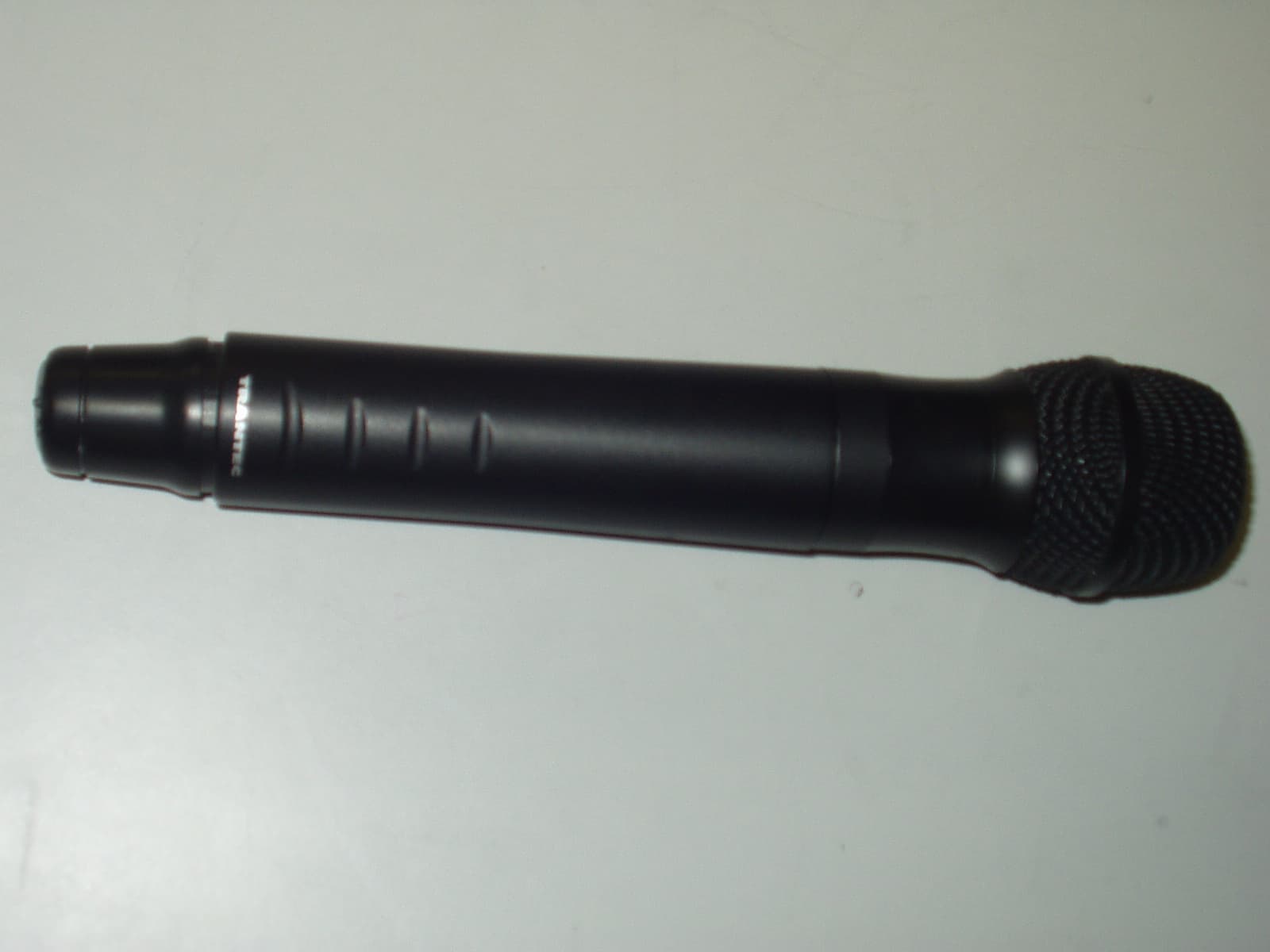
Click to zoom
Application Details
- Equipment Class
- TBF - Licensed Broadcast Transmitter Held to Face
- Date of Grant
- Jan 09, 2008
- Application Purpose
- Original Equipment
- Date of Application
- Jan 07, 2008
- Equipment Note
- S5 Series Handheld Transmitter
- Frequency Range
- 685.90000000 - 758.10000000
- Company
- BBM Electronics Group Ltd
- Country
- United Kingdom
Documents & Files
Document Text
Text extracted from the exhibit documents filed with the FCC. Open a document above to read the original.
Users Manual
Trantec S5 Wireless Microphone Series Q U I C K I N S TA L L AT I O N G U I D E Trantec S5 Wireless Microphone Series S5_manualV1.2.indd 125/10/07 17:18:09 CONTENTS Page 1. Introduction and system overview 2. Important safety instructions and getting started 3. Receiver set-up 4. Receiver frequency selection 5. Handheld transmitter set-up 6. Beltpack transmitter set-up 7. Operating hints and troubleshooting guide 8. Receiver rack mount kit 9. Technical specifications 10. WEEE statement and warranty INTRODUCTION The Trantec S5 series represents our commitment to our customers by providing high- quality, reliable wireless audio links using our considerable design expertise gained over many years as a leading edge manufacturer. We would like to thank you for purchasing this product and would like you to spend a few moments studying this Quick Installation Guide, especially the safety instructions, before going on to ‘read’ the full manual supplied on the CD Rom with this equipment. S5 SERIES SYSTEM OVERVIEW The S5 series is a professional UHF wireless microphone system with features including: • 24 channel simultaneous operation (12 channel S5.3) • 10 preset banks including 1 custom user. (9 Banks S5.3) • True “dual receiver” diversity – to minimise drop-outs • Intuitive LCD and operating system on both receiver and transmitter • Infra-red programming for fast system set-up • Software transmitter function locks • Headphone monitoring as standard • Both XLR (switchable mic and line) and 1⁄4” jack AF outputs • AF processing menu (S5.5 only) • Over 1400 customer selectable channels • Fully integrated PC software monitoring facility via USB port • All metal construction of receiver and transmitters • Rack kit and front mounting antenna adaptors included (S5.5 only) 1 S5_manualV1.2.indd 225/10/07 17:18:09 SAFETY Our aim is to supply you with a product that provides you with countless hours of trouble free use. In order to achieve these goals we recommend the following: • Keep the system away from direct sources of heat e.g. central heating radiators, heaters and direct sunlight. • Do not expose the unit to an environment where it could be splashed with liquids as this may result in fire or electric shocks. • Should the transmitters not be used for extended periods of time we recommend that the batteries are removed to avoid any potential leakage. • Keep the system clean by using a slightly damp cloth. Never use household cleaning agents or solvents. • Avoid using or storing the system in damp conditions. • Always use the AC power adaptor supplied with the receiver and always disconnect from the AC outlet when not in use. And never remove the external covers of the equipment, so as to expose the electronics, or modify the unit in any way. Should the covers be removed, or any other breach of the above instruction, the warranty becomes null and void in addition to personal risk from burns and/or electric shock. When using the unit should any of the following conditions occur, switch off the unit and remove AC adaptor from AC outlet immediately and contact your nearest dealer. • Smoke or unusual smell • Water or foreign metallic object inside unit • Damaged housings caused by physical damage Never pull cord of AC adaptor, always grasp main body of unit when connecting/ disconnecting to AC power outlet Never touch any part of the system during a thunderstorm, as this may result in severe electric shock GETTING STARTED The S5 series is a high quality, fully featured wireless microphone system with many features including an intuitive operating system. To enable you to get started we recommend you initially set up the system as outlined in the next few pages. 2 S5_manualV1.2.indd 325/10/07 17:18:09 RECEIVER SET-UP Rear View Front View 1. Attach the supplied antennae (2) to the rear panel TNC antenna connectors as shown in above illustration. 2. Connect the AC/DC adaptor into the DC inlet as marked on the rear panel using the attached cable strain relief. Observe the front panel on-off switch surround is illuminated red. 3. Connect the rear panel AF output from either the 1/4” Jack or XLR to your mixing console or amplifier. Note: the XLR balanced output can be switched for either mic or line. The system can be also monitored from the headphone socket using the “Jog-Wheel” to adjust Volume level. 4. Switch On-Off switch to “On” position and the receiver will default to initial setting as per illustration above. (BK1.01) The system is now ready for use. DC inlet 1/4” jack output DC strain relief Mic/Line switch USB port XLR output Diversity switch A/B indicators Infra-red port Power switch indicator Power On/Off LCD Jog wheel Mute indicator Headphone output 3 S5_manualV1.2.indd 425/10/07 17:18:10 RECEIVER FREQUENCY SELECTION 5. Frequency selection options • To change selected channel in BANK1: Press “Jog-wheel” for 3 secs and enter the MAIN MENU. Press FREQ SELECT and go to BANK setting, then select BANK1 and rotate jog wheel to select new channel, finally press to ACCEPT to select new frequency. See attached frequency table. • To change selected Bank: Press “Jog-wheel” for 3 secs and enter the MAIN MENU. Press FREQ SELECT and go to BANK setting, then select required BANK by rotating and pressing “Jog-Wheel” Select new channel, finally press ACCEPT to select new frequency. Go to step 6 to program transmitter via the Receiver Infra-red port. • To change selected channel to a Custom single frequency. This option allows the customer to select 1 of over 1400 available channels: Press “Jog-wheel” for 3 secs and enter the MAIN MENU. Press FREQ SELECT and go to SINGLE press EDIT and rotate and press “Jog-Wheel” to Select new frequency and User Name. Press “Jog-Wheel” for 3 secs to EXIT then ACCEPT to select new custom frequency. Go to step 6 to program transmitter via the Receiver infra-red port. Please note: For S5.3 product the single user frequency will be added to Transmitter with receiver Bank1. In the cas…
Text truncated - open the document above for the full version.
Cover Letter(s)
bbm A Division of TOA CORPORATION OF JAPAN Electronics Group Limited KESTREL HOUSE GARTH ROAD MORDEN SURREY SM4 4LP TEL : 44 (0) 20-8330 3111 FAX : 44 (0) 20-8330 3222 E - MAIL : [email protected] WEB SITE : www.trantec.co.uk Request for confidentiality Date 6 th December 2007 American Telecommunications Certification Body, Inc. 6731 Whittier Avenue Suite C110 McLean, VA 22101 RE: Certification Application FCC ID: F3SS5HX To Whom It May Concern: Please be advised that the following information is to be held confidential on behalf of TOA Corporation and/or it’s subsidiaries. • All detailed schematic and Block diagrams and parts list. • All items containing detailed technical description of product. The application contains technical information which TOA Corporation deems to be trade secrets and propriety. If made public, the information might be used to the disadvantage of the applicant in the market place. Thank you for your attention to this matter. Yours faithfully For and on Behalf of TOA CORPORATION Steven Baker TOA CORPORATION 2-1 TAKAMATSU-CHO, TAKARAZUKA, HYOGO 665 JAPAN. 0797-71-2218
Cover Letter(s)
bbm A Division of TOA CORPORATION OF JAPAN Electronics Group Limited KESTREL HOUSE GARTH ROAD MORDEN SURREY SM4 4LP TEL : 44 (0) 20-8330 3111 FAX : 44 (0) 20-8330 3222 E - MAIL : [email protected] WEB SITE : www.trantec.co.uk Letter of Agency Date 6 th December 2007 American Telecommunications Certification Body, Inc. 6731 Whittier Avenue Suite C110 McLean, VA 22101 To Whom It May Concern: R.N. Electronics is authorised to act on our behalf, until otherwise notified, for applications to American Telecommunications Certification Body, Inc. (ATCB). We certify that we are not subject to denial of federal benefits, that includes FCC benefits, pursuant to Section 5301 of the Anti-Drug Abuse ACT of 1988, U.S.C. 862. Further, no party, as defined in 47 CFR 1.2002(b), to the application is subject to denial of federal benefits, that includes FCC benefits. Thank you for your attention to these matters. Yours faithfully For and on Behalf of TOA Corporation Steven Baker TOA CORPORATION 2-1 TAKAMATSU-CHO, TAKARAZUKA, HYOGO 665 JAPAN. 0797-71-2218
Cover Letter(s)
American Telecommunications Certification Body Inc. 6731 Whittier Ave, McLean, VA 22101 January 5, 2008 RE: FCC ID: F3SS5HX_ATCB005796 Attention: Paul Darragh I have a few comments on this Application. Please note that further comments may arise in response to answers provided to the questions below. 1. Please note that part of the label exhibit requirement is the explanation of how the label is fastened to the device and how it is made permanent. While the exhibit shows the label and where it is placed on the device, there is no information on what it is made of and how it is permanently attached. Please explain. 2. Please note that the statement in the label placement states “Battery Compartment”. Please confirm that the label is inside the battery compartment and is not on the removable battery cover. 3. Please note that you list TIA603 in the report on page 6 as a ‘relevant standard’. However, in the test methods section of the actual tests you do not list TIA603 but instead list “47CFR Part 2, Subpart J, Clause 2.1046. Then you state in the text of the test that testing was done in accordance to the test method ‘listed above’. Please note that 2.1046 is not test method and that the accepted test method would be the TIA603 listed on page 6. Please confirm that testing was performed in accordance to TIA603 in this and the other tests in the report. 4. Please note that the operational description states that the final output stage is “biased by R27 so as to provide an output of not more than 10mW.” Please note that the tune up procedure states “Adjust it in [R27:20k Pot] -> 10+/-1dBm.” Please note that this would give an allowable tune up range of 7.9mW to 12.5mW. Please note that the output measured in the test report is 17.8mW or 178% higher than the design parameters of the device. Please tune the device to the allowed power range and retest conducted power to be in line with the tune up procedure and the operational description. Alternately, please correct the other documentation to account for the use of 17.8mW. 5. Please note that in the ERP measurements you only show the final results. Please note that the actual measured level into the substitution antenna and the gain of the substitution antenna need to be provided to see how device is shown compliant. Please provide the measurement data and please clearly state the calculation method used to determine ERP. 6. Please note that it is assumed by the reviewer that the manual for this device is the same as for the S5LX also being certified. I have copied the manual into the file exhibits. Please confirm or please provide the appropriate correct manual. Dennis Ward mailto:[email protected] The items indicated above must be submitted before processing can continue on the above referenced application. Failure to provide the requested information may result in application termination. Correspondence should be considered part of the permanent submission and may be viewed from the Internet after a Grant of Equipment Authorization is issued. Please do not respond to this correspondence using the email reply button. In order for your response to be processed expeditiously, you must submit your documents through the AmericanTCB.com website. Also, please note that partial responses increase processing time and should not be submitted. Any questions about the content of this correspondence should be directed to the sender.
ID Label/Location Info
FCC ID Label Artwork and Label Location. Example Handheld labels: (battery compartment) (front face)
ID Label/Location Info
Label Material 7813 Thermal Transfer Polyester Label Material Product Data Sheet Updated : April 2000 Supersedes: March 1999 Physical Properties Not for specification purposes Facestock 84 micron (3.3 thou) Matte Silver polyester (Calipers are nominal values) Adhesive 20 micron (0.8 thou) #300 Acrylic Liner 81 micron (3.2 thou), 90 g/m 2 (#55) Densified kraft Shelf Life 24 months from date of manufacture of product when properly stored between 22°C and 50% relative humidity. Features: • Matte topcoat provides the advantages of matte coating combined with a surface that is smooth enough for thermal transfer printing. Resin ribbons are recommended for optimum durability. The matte coating resists degradation from scuffing, chemicals, moisture, and wide temperature fluctuations. The topcoat also provides improved ink anchorage for traditional forms of press printing. • #300 adhesive bonds well to a wide variety of substrates including metals, high surface energy (HSE) plastics and low surfaces energy (LSE) plastics. It is ideal for applications requiring high initial adhesion especially to LSE plastic surfaces. • 90 g/m 2 , (55#) densified kraft liner assures consistent die cutting. • 3M Label Material 7813 is UL recognised (File MH16411) and CSA accepted (File 99316). See the UL and CSA listings for details. Application Ideas: •Barcode labels and rating plates. •Property identification and asset labelling. •Warning, instruction, and service labels for durable goods. •Nameplates for durable goods. •Substitutes for stamped metal, riveted plates 2 Date : April 2000 Label Material 7813 Thermal Transfer Polyester Label Material Performance Characteristics Not for specification purposes Adhesion 180° peel test procedure is ASTM D 3330 90° peel test procedure is ASTM D 3330 modified for the angle change Initial (10 Minute Dwell/RT) Surface 180º Peel90º Peel N/10mmOz/InN/10mmOz/In Stainless Steel 6.1564.642 Polycarbonate 6.7594.844 Polypropylene 5.8534.238 Glass 6.6604.642 HD Polyethylene 3.8353.128 LD Polyethylene 3.5322.725 Conditioned for 3 Days at Room Temperature 22ºC Surface 180º Peel90º Peel N/10mmOz/InN/10mmOz/In Stainless Steel 7.3675.046 Polycarbonate 6.7615.046 Polypropylene 6.1564.238 Glass 7.8715.248 HD Polyethylene 4.4403.128 LD Polyethylene 4.6423.734 Conditioned for 3 Days at 49ºC Surface 180º Peel90º Peel N/10mmOz/InN/10mmOz/In Stainless Steel 7.7705.550 Polycarbonate 3.3301.917 Polypropylene 5.9544.642 Glass 7.7705.550 HD Polyethylene 4.4403.229 LD Polyethylene 1.091.110 Conditioned for 24 hours at 32ºC At 90% Relative Humidity Surface 180º Peel90º Peel N/10mmOz/InN/10mmOz/In Stainless Steel 7.4685.853 Polycarbonate 6.0553.936 Polypropylene 7.2664.844 Glass 7.3674.844 HD Polyethylene 4.9453.532 LD Polyethylene 3.9363.330 3 Date : April 2000 Label Material 7813 Thermal Transfer Polyester Label Material Performance Characteristics Contd... Not for specification purposes Liner Release 180º Removal of Liner from Facestock Rate of RemovalN/10mmGms/25mm Width 2.3 m / min0.05414 7.6 m / min0.06918 Environmental Performance The properties defined are based on four hour immersions at room temperature 22ºC unless otherwise noted. Samples were applied to stainless steel panels 24 hours prior to immersion and were evaluated one hour after removal from the solution for peel adhesion. Adhesion measured at 180º peel angle (ASTM D3330) at 305 mm/min. Chemical Resistance Adhesion to Stainless Steel AppearanceEdge Penetration ChemicalN/10mmOz/InVisualMillimetres Isopropyl Alcohol 6.660No change0.8 Detergent (1% Alconox®*) 7.064No change0 Engine Oil (10W30) @ 250ºF (121ºC) 7.064No change1 Water for 48 hours 7.266No change0 pH 4 7.165No change0 PH10 7.064No change0 409 8 * Cleaning solution7.064No change0 Toluene 3.633Topcoat Damaged 6.5 Acetone 5.147Topcoat Damaged or Gone 4.3 Brake Fluid 8.174No change0 Gasoline 3.936No change5.8 Diesel Fuel 6.862No change1 Mineral Spirits 5.954No change2.4 Hydraulic Fluid 7.266No change0 Temperature Resistance 149°C for 24 hours: no significant visual change 0.7% MD shrinkage 0.9% CD shrinkage -40°C for 3 days: no significant visual change Humidity Resistance 24 hours at 38°C and 100% relative humidity no significant changes in appearance or adhesion 4 Date : April 2000 Label Material 7813 Thermal Transfer Polyester Label Material Accelerated Ageing ASTM D3611 : 96 hours at 65ºC & 80% relative humidity Rate of RemovalN/10mmGrams/In Width 180º Removal of Liner from Facestock90 in. / minute6.216 Rate of RemovalN/10mmOz/In Width 180º Peel Adhesion from Stainless Steel12 in. / minute545.9 Agency Listing Information Thermal Transfer Printing: Printer: UL no longer requires evaluation and listing of specific printers. *Ink Ribbon/UL Recognised Components Advent: 301 Black; 303 Black; 501 Black; 501 Red; 501 Blue; 501 Green Armor: AXR-7; AXR-7+; AXR-600 Astromed: R5 CP: 5440 Red; 5640 Blue; 5940 Black Dasco: DR-74; DR-84 Great Ribbon: SDR; GPR ICS: ICS-CC-2000; ICS-CC-4099.1 Iimak: SH-36; SP-330: PrimeMark Intermec: 051864-3; 053258-2; 054048-4; 054195-2 Japan Pulp and Paper: JP Resin 1; JP Resin 2 Blue; JP Resin 2 Red; JP Resin 2 Green Kurz: K501 Markem: 716 Mid City Columbia: CGL-80; CGL-80HE NCR: Matrix Resin; Matrix (suitable for indoor use only) ; Pace Setter; Promark II; Ultra V Pelikan: T016 Ricoh: B110A, B110C, B110CS Sato: Premier 1 Sony: 4050, 4051, 4070; 4072; 4075; 4085; 5070; Signature Series Resin; Signature Series Wax UBI: HR03; HR04 Zebra: 5095, 5097, 5099, 5100, 5175, 5555 Laser Toner Printing UL recognised with the following printers and toners. *Toner and Printer/UL Recognised Components Hitachi HMT 446 toner kit for producing finished printed labels with UL listed Synergystex CT-1000 laser printer. 5 Date : April 2000 Label Material 7813 Thermal Transfer Polyester Label Material Processing Printing: Facestock is topcoated for improved ink receptivity and is designed for thermal transfer printing. It is printable by all standard roll p…
Text truncated - open the document above for the full version.
Test Report
File name BBM.217A PAGE 1 OF 48 QMF21J – 3; FCC CFR 47 PART 2 J OCT 2004; RNE ISSUE 02 NOV 07 FCC Licensed Transmitter Test Report for S5 series Handheld transmitter S5.5HDX Reference Standard 47CFR Part 2, Subpart J: Oct 2007 Manufacturer: BBM Electronics Group Ltd For type of equipment and serial number, refer to section 3 Report Number 10-217A/3479/3/07 Supersedes report number 10-217/3479/3/07 Report Produced by: - R.N. Electronics Ltd. 1 Arnolds Court Arnolds Farm Lane Mountnessing Essex CM13 1UT U.K. www.RNelectronics.com Telephone +44 (0) 1277 352219 Facsimile +44 (0) 1277 352968 EMC & RADIO TEST SERVICES S RN Electronics ©2004 RN ELECTRONICS LIMITED REPORT NUMBER 10-217A/3479/3/07 ALL RIGHTS RESERVED File name BBM.217A PAGE 2 OF 48 QMF21J – 3; FCC CFR 47 PART 2 J OCT 2004; RNE ISSUE 02 NOV 07 This page has been left blank intentionally. ©2004 RN ELECTRONICS LIMITED REPORT NUMBER 10-217A/3479/3/07 ALL RIGHTS RESERVED File name BBM.217A PAGE 3 OF 48 QMF21J – 3; FCC CFR 47 PART 2 J OCT 2004; RNE ISSUE 02 NOV 07 1. Contents 1. CONTENTS............................................................................................................................................... 3 2. SUMMARY OF TEST RESULTS...................................................................................................................... 4 3. INFORMATION ABOUT EQUIPMENT UNDER TEST................................................................................... 5 4. SPECIFICATIONS....................................................................................................................................... 6 4.1 Relevant Standards ............................................................................................................... 6 4.2 Deviations Applied ............................................................................................................... 6 4.3 Measurement Uncertainty..................................................................................................... 6 4.4 Tests at Extremes of Temperature and Voltage.................................................................... 6 5. TESTS, METHODS AND RESULTS................................................................................................................. 7 5.1 Carrier Power........................................................................................................................ 7 5.2 Modulation Characteristics................................................................................................... 9 5.3 Occupied Bandwidth .......................................................................................................... 11 5.4 Spurious Emissions at Antenna Terminals ......................................................................... 12 5.5 Field Strength of Spurious Radiation. ................................................................................ 14 5.6 Frequency Error.................................................................................................................. 16 6. GRAPHICAL RESULTS................................................................................................................................17 6.1 Conducted Emissions. ........................................................................................................ 17 6.2 Modulation Limiting........................................................................................................... 32 6.3 Audio Response..................................................................................................................34 6.4 Channel Bandwidth. ........................................................................................................... 36 7. PHOTOGRAPHS........................................................................................................................................... 39 7.1 EUT Front View .................................................................................................................39 7.2 EUT Antenna...................................................................................................................... 40 7.3 EUT Display / Controls ...................................................................................................... 41 7.4 EUT Internal Construction ................................................................................................. 42 7.5 Test set-up, spurious emissions .......................................................................................... 44 8. SIGNAL LEADS....................................................................................................................................... 45 9. TEST EQUIPMENT CALIBRATION LIST....................................................................................................... 46 10. AUXILIARY EQUIPMENT........................................................................................................................ 47 10.1 Supplied by BBM Electronics ............................................................................................ 47 10.2 Supplied by RN Electronics Limited .................................................................................. 47 11. MODIFICATIONS.................................................................................................................................... 48 ©2004 RN ELECTRONICS LIMITED REPORT NUMBER 10-217A/3479/3/07 ALL RIGHTS RESERVED File name BBM.217A PAGE 4 OF 48 QMF21J – 3; FCC CFR 47 PART 2 J OCT 2004; RNE ISSUE 02 NOV 07 2. Summary of Test Results The S5 series Handheld transmitter S5.5HDX was tested for compliance to the following standard for licensed transmitters: - 47CFR Part 2, Subpart J: Oct 2007 47CFR Part 74, Subpart H: Oct 2007 Class TBF Intentional Radiator Title References Results conducted: PASSED 1. RF Power Output. 47CFR Part 2, Subpart J radiated: PASSED frequency response: PA…
Text truncated - open the document above for the full version.
Contact Information
Applicant
Steve Baker
011 44 181 330 3111Fax: 011 44 181 330 3222
Technical Specifications
| # | Rule Parts | Frequency Range | Power Output | Emission | Tolerance |
|---|---|---|---|---|---|
| 1 | 74.861 | 685.9 MHz - 758.1 MHz | 8.13 mW | 200KG3E | 0.0050000000 % |
Other Applications from BBM Electronics Group Ltd
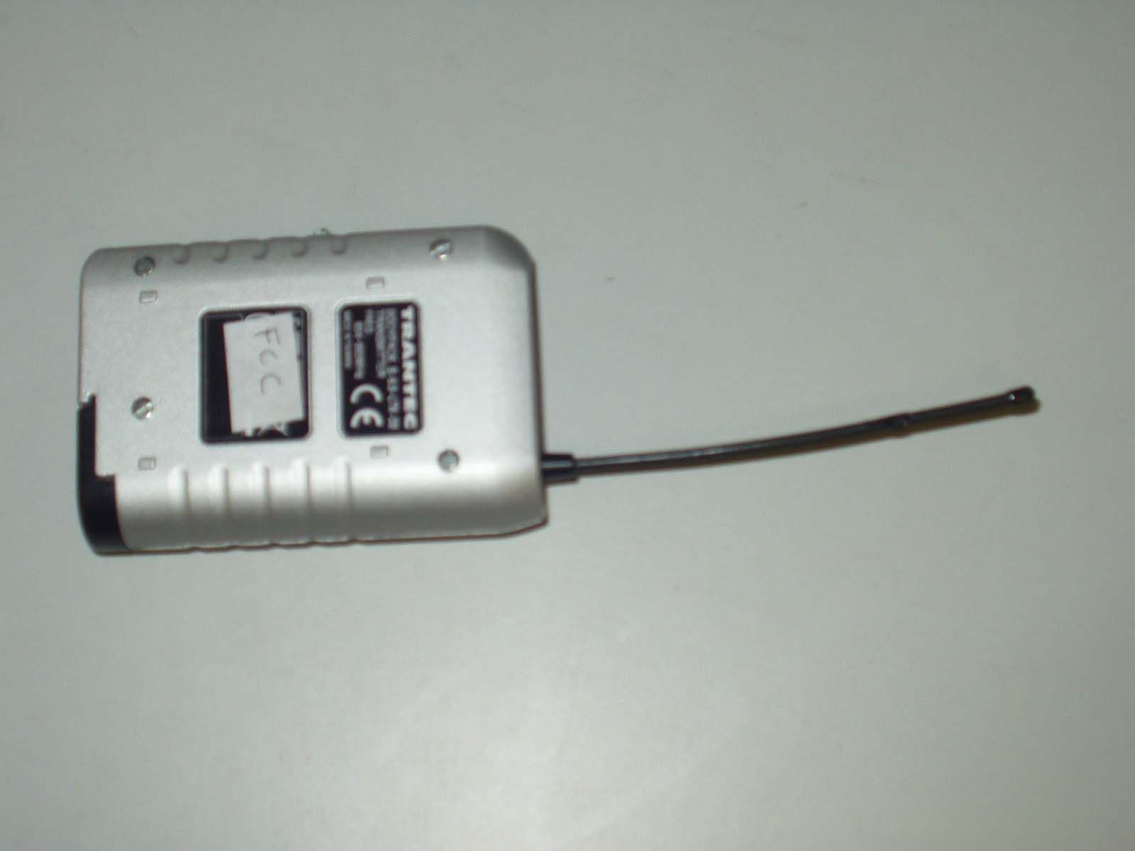
F3SS5LX
Jan 09, 2008S5 Series Beltpack Transmitter
Equipment Class
TBT - Licensed Broadcast Transmitter Worn on Body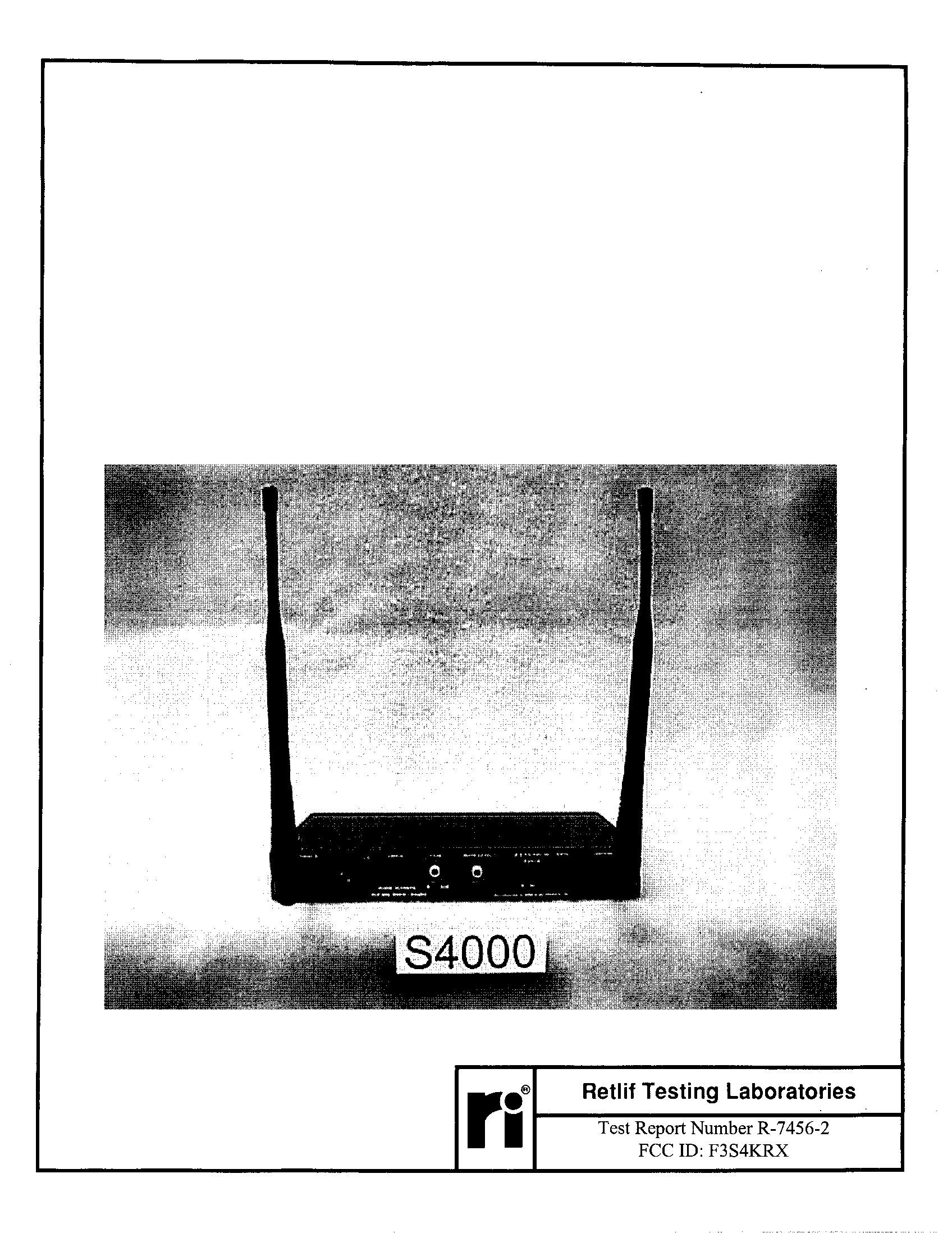
F3S4KRX
Jun 30, 1998CXX - Communications Rcvr for use w/ licensed Tx and CBs
Equipment Class
CXX - Communications Rcvr for use w/ licensed Tx and CBsF3S35KRX
Jun 29, 1998Wireless Mic Receiver
Equipment Class
CXX - Communications Rcvr for use w/ licensed Tx and CBsF3S5KRX
Jun 10, 1998CXX - Communications Rcvr for use w/ licensed Tx and CBs
Equipment Class
CXX - Communications Rcvr for use w/ licensed Tx and CBs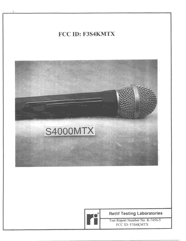
F3S4KMTX
Jun 08, 1998TBF - Licensed Broadcast Transmitter Held to Face
Equipment Class
TBF - Licensed Broadcast Transmitter Held to Face