F5J9192727MHz WIRELESS R/C CAR - TX
Ka Wah Manufactory Limited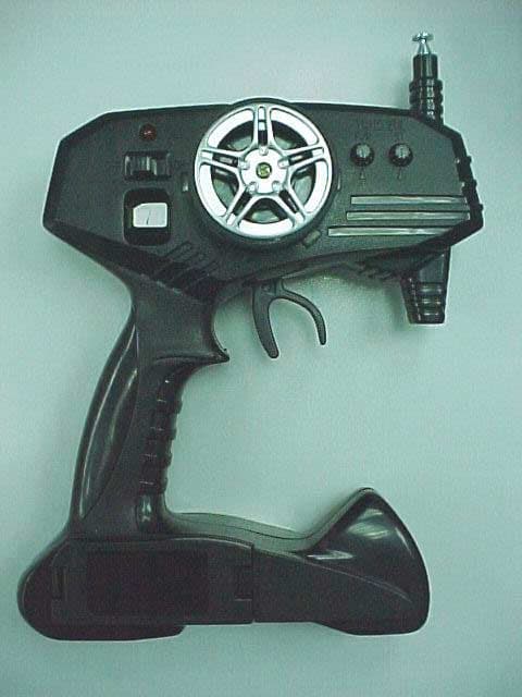
Click to zoom
Application Details
- Equipment Class
- DXX - Part 15 Low Power Communication Device Transmitter
- Date of Grant
- Sep 25, 2003
- Application Purpose
- Original Equipment
- Date of Application
- Sep 25, 2003
- Equipment Note
- 27MHz WIRELESS R/C CAR - TX
- Frequency Range
- 26.96000000 - 27.28000000
- Company
- Ka Wah Manufactory Limited
- Country
- Hong Kong
Documents & Files
Document Text
Text extracted from the exhibit documents filed with the FCC. Open a document above to read the original.
Users Manual
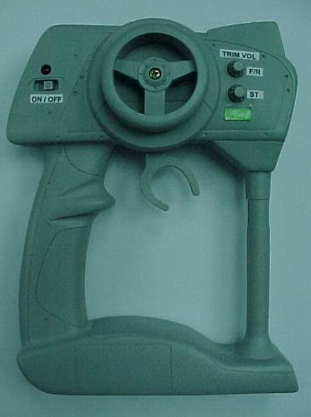
Honda CR250R Motocross Bike featuring Ricky Carmichael60-4353 What’s Included Installing BatteriesYou will need...• Four AA batteries for the motorcycle• One 7.2V rechargeable Ni-Cd or Ni-MH battery pack (not included) • One battery charger (not included)• One 9V battery for the transmitter (not included)• Phillips screwdriver (not included)Put AA Batteries in the Motorcycle• Loosen the screw on the battery box cover, located on the seat of the motorcycle, and remove the cover. • Take out the battery holder and insert four AA batteries, matching the polarity symbols (+ and -) marked inside. • Replace the battery holder and cover, and then secure it with the screw. Put Rechargeable Battery Pack in Motorcycle• Loosen the screw on the battery compartment cover, located on the bottom of the motorcycle, and remove the cover. • Place the battery pack in the compartment, attaching the battery pack’s white plastic connector to the motorcycle’s matching connector. Do not force them together. They only fit one way. • Replace the cover and secure it with the screw.Put Battery in the Transmitter• Remove the battery compartment cover. • Insert the battery in the transmitter, matching the polarity (+ and -) symbols marked inside. • Replace the cover. Installing the Antenna• Route the loose end of the motorcycle’s antenna wire through the supplied antenna tube.• Insert the tube securely into the motorcycle’s tube holder.• Extend the transmitter’s antenna to its full length before driv ing the motorcycle. For maximum range, hold the transmitter with the antenna as high as possible and point it straight up. • Retract the transmitter’s antenna when you are finished driving the motorcycle. Step One Step Two Motorcycle ♦ Transmitter ♦ Ricky Carmichael Action Figure Display Stand ♦ Antenna Tube ♦ Two 4-Way Wrenches Three Allen Wrenches ♦ Owner’s Manual Adjusting the Trim ControlsAdjust the trim controls to ma ke the motorcycle drive properly. Throttle Trim• Place your motorcycle on the displa y stand so the rear wheel does not touch the ground. • Turn the transmitter and motorcycle on and pull the throttle trigger.• If the rear wheel moves, turn the TRIM VOL F/R on the transmitter clockwise or counter-clockwise until the wheel stops. Never use the throttle trim to make the motorcycle go.Steering TrimIf your motorcycle does not drive in a st raight line, turn the TRIM VOL ST left or right until your motorcycle moves in a straight line. Release the steering wheel before you make the adjustment. Driving the Motorcycle• Turn the motorcycle and transmitter on. The LED lights on the transmitter. • Position the motorcycle straight and upright, holdi ng the back of the seat and lifting the rear wheel off the ground. • Pull the transmitter’s throttle trigger to full speed and release the motorcycle. Warning: Keep your fingers away from the spinning tire. • When you finish driving, turn the motorcycle off fi rst, and then turn the transmitter off. See Page 2 for Driving Tips. Transmitter Controls• Throttle Trigger - Pull the trigger back toward the grip to move forward. Release the trigger to stop.• Throttle Trigger Brake - The throttle trigger is us ed to slow the motorcycle down also. Push the trigger forward to apply the brake and reduce speed. • Steering Wheel - Steer the wheel left to go left. Steer the wheel right to go right. Release the wheel to go straight. Step Three Throttle Trigger Steering Wheel LED OFF/ON Switch 9V Battery Chamber Trim F/R Trim ST Trim ControlsTRIM VOL F/R - Adjusts the throttle so the motorcycle stops completely when you release the trigger. If the trim is not set properly, the motorcycle might continue to move forward when you release the trigger.TRIM VOL ST - Adjusts the wheel alignment so the motorcycle drives in a straight line when you release the steering wheel. Recreate all of your favorite Ricky Carmichael moves by adjusting the head, arms and legs, while racing at an impressive 20 m.p.h.! Cool Stunts • When driving at a medium or high speed, the motorcycle may raise the front tire off the ground if you drive on a surface that has small bumps or obstacles. • To fish tail the motorcycle, start making a turn at a low speed. Then, immediately change the direction of the turn and increase the speed. • You can perform jumps with your motorcycle off ramps eight inches high or less. Hint: When transporting your motorcycle, do not pick it up by the driver’s head. Use both hands to support the motorcycle, one underneath the motorcycle and the other on the rear of the seat. Battery Notes ©2003. RadioShack Corporation. 60-4353 All Rights Reserved. Printed in China RadioShack and RadioShack.com are trademarks 08A03 used by RadioShack Corporation. This product is warranted by RadioShack against manufacturing defects in material and workmanship under normal use for ninety (90) days from the date of purchase from RadioShac k company-owned stores and authorized RadioShack franchisees and dealers. EXCEPT AS PROVIDED HEREIN, RadioShack MA KES NO EXPRESS WARRANTIES AND ANY IMPLIED WARRANTIES, INCLUDING THOSE OF MERCHANTABILITY AND FITNESS FOR A PARTICULAR PURPOSE, ARE LIMITED IN DURATION TO THE DURATION OF THE WRITTEN LIMITED WARRANTIES CONTAINED HEREIN. EXCEPT AS PROVIDED HEREIN, RadioShack SHALL HAVE NO LIABILITY OR RESPONSIBILITY TO CUSTOMER OR ANY OTHER PERSON OR ENTITY WITH RESPECT TO ANY LIABILITY, LOSS OR DAMAGE CAUSED DIRECTLY OR INDIRECTLY BY USE OR PERFORMANCE OF THE PRODUCT OR ARISING OUT OF ANY BREACH OF THIS WARRANTY, INCLUDING, BUT NOT LIMITED TO, ANY DAMAGES RESULTING FROM INCONVENIENCE, LOSS OF TIME, DATA, PROPERTY, REVENUE, OR PROFIT OR ANY INDIRECT, SPECIAL, INCIDENTAL, OR CONSEQUENTIAL DAMAGES, EVEN IF RadioShack HAS BEEN ADVISED OF THE POSSIBILITY OF SUCH DAMAGES.Some states do not allow limitations on how long an implied warranty lasts or the exclusion or limitation of incidental or consequential damages, so the above limitations or exclusions may not apply to you.In the event…
Text truncated - open the document above for the full version.
Operational Description
Model 60-4353 Motorcycle CIRCUIT DESCRIPTION This unit is a low power remote control transmitter consisting two transistors in the RF circuitry. Q1 is a crystal control oscillator. Transistor Q3 is the output stage. This unit operates in the 27MHz RC band. The transistor Q2 is the voltage regulator to supply voltage to oscillator Q1 and IC1. The IC 1 generate the control signal to modulate RF signal. No voice or tone modulation is provided. ANTENNA & GROUND This unit uses a telescopic antenna. The antenna is self contained and there is no provision for connecting an external antenna. No ground connection is provided. The only ground used is the ground track on the PCB.
Test Report
TIMCO TIMCOTIMCO TIMCO ENGINEERING INC. 849 NW State Road 45 Newberry, Florida 32669 http://www.timcoengr.com 888.472.2424 F 352.472.2030 email: [email protected] APPLICANT: KA WAH MANUFACTORY LTD. FCC ID: F5J91927 REPORT #: K\KAWAHF5J\1215HT3\1215HT3TestReport.doc COVER SHEET Test Report Product Name: 27MHz WIRELESS R/C CAR - TX FCC ID: F5J91927 Applicant: KA WAH MANUFACTORY LTD. WAH HING IND. MANSIONS, 10/F FLAT F 36, TAI YAU STREET, SAN PO KONG KOWLOON HONG KONG Date Receipt: AUGUST 27, 2003 Date Tested: SEPTEMBER 4, 2003 TIMCO TIMCOTIMCO TIMCO ENGINEERING INC. 849 NW State Road 45 Newberry, Florida 32669 http://www.timcoengr.com 888.472.2424 F 352.472.2030 email: [email protected] APPLICANT: KA WAH MANUFACTORY LTD. FCC ID: F5J91927 REPORT #: K\KAWAHF5J\1215HT3\1215HT3TestReport.doc TABLE OF CONTENTS TABLE OF CONTENTS LIST APPLICANT: KA WAH MANUFACTORY LTD. FCC ID: F5J91927 TEST REPORT CONTAINING: PAGE 1...............TEST EQUIPMENT LIST PAGE 2...............TEST PROCEDURE PAGE 3...............RADIATION INTERFERENCE TEST DATA PAGE 4...............OCCUPIED BANDWIDTH PAGE 5...............OCCUPIED BANDWIDTH PLOT EXHIBITS CONTAINING: EXHIBIT 1............BLOCK DIAGRAM EXHIBIT 2............SCHEMATIC EXHIBIT 3............INSTRUCTION MANUAL EXHIBIT 4............LABEL SAMPLE EXHIBIT 5............LABEL LOCATION EXHIBIT 6............EXTERNAL PHOTOGRAPHS EXHIBIT 7............INTERNAL PHOTOGRAPHS EXHIBIT 8............CIRCUIT DESCRIPTION EXHIBIT 9............TEST SET UP PHOTOGRAPHS TIMCO TIMCOTIMCO TIMCO ENGINEERING INC. 849 NW State Road 45 Newberry, Florida 32669 http://www.timcoengr.com 888.472.2424 F 352.472.2030 email: [email protected] APPLICANT: KA WAH MANUFACTORY LTD. FCC ID: F5J91927 REPORT #: K\KAWAHF5J\1215HT3\1215HT3TestReport.doc Page 1 of 5 Equipment List Device Manufacturer Model Serial Number Cal/Char Date Due Date 3/10-Meter OATS TEI N/A N/A Listed 3/26/01 3/26/04 3-Meter OATS TEI N/A N/A Listed 1/13/03 1/13/06 Biconnical Antenna Eaton 94455-1 1057 CAL 3/18/03 3/18/05 Biconnical Antenna Eaton 94455-1 1096 CAL 10/1/01 10/1/03 Biconnical Antenna Electro- Metrics BIA-25 1171 CAL 4/26/01 4/26/03 Blue Tower Quasi-Peak Adapter HP 85650A 2811A01279 CAL 4/15/03 4/15/05 Blue Tower RF Preselector HP 85685A 2926A00983 CAL 4/15/03 4/15/05 Blue Tower Spectrum Analyzer HP 8568B 2928A04729 2848A18049 CAL 4/15/03 4/15/05 LISN Electro- Metrics ANS-25/2 2604 CAL 10/9/01 10/9/03 LISN Electro- Metrics EM-7820 2682 CAL 3/12/03 3/12/05 Log-Periodic Antenna Eaton 96005 1243 CAL 5/8/03 5/8/05 Log-Periodic Antenna Electro- Metrics EM-6950 632 CHAR 10/15/01 10/15/03 Log-Periodic Antenna Electro- Metrics LPA-25 1122 CAL 10/2/01 10/2/03 Log-Periodic Antenna Electro- Metrics LPA-30 409 CAL 3/4/03 3/4/05 Silver Tower Preamplifier HP 8449B 3008A01075 CHAR 1/28/02 1/28/04 Silver Tower Quasi-Peak Adapter HP 85650A 3303A01844 CAL 10/14/02 10/14/04 Silver Tower RF Preselector HP 85685A 2620A00294 CAL 10/14/02 10/14/04 Silver Tower Spectrum Analyzer HP 8566B Opt 462 3552A22064 3638A08608 CAL 10/14/02 10/14/04 Tan Tower Preamplifier HP 8449B-H02 3008A00372 CHAR 3/4/01 3/4/03 Tan Tower Quasi-Peak Adapter HP 85650A 3303A01690 CAL 8/31/01 8/31/03 Tan Tower RF Preselector HP 85685A 3221A01400 CAL 8/31/01 8/31/03 Tan Tower Spectrum Analyzer HP 8566B Opt 462 3138A07786 3144A20661 CAL 8/31/01 8/31/03 TIMCO TIMCOTIMCO TIMCO ENGINEERING INC. 849 NW State Road 45 Newberry, Florida 32669 http://www.timcoengr.com 888.472.2424 F 352.472.2030 email: [email protected] APPLICANT: KA WAH MANUFACTORY LTD. FCC ID: F5J91927 REPORT #: K\KAWAHF5J\1215HT3\1215HT3TestReport.doc Page 2 of 5 TEST PROCEDURE GENERAL: This report shall NOT be reproduced except in full without the written approval of TIMCO ENGINEERING, INC. RADIATION INTERFERENCE: The test procedure used was ANSI STANDARD C63.4- 1992 using a HEWLETT PACKARD spectrum analyzer with a pre-selector. The bandwidth of the spectrum analyzer was 100 kHz with an appropriate sweep speed. The analyzer was calibrated in dB above a microvolt at the output of the antenna. The resolution bandwidth was 100 kHz and the video bandwidth was 300 kHz. The ambient temperature of the UUT was 80ºC with a humidity of 76%. FORMULA OF CONVERSION FACTORS: The Field Strength at 3m was established by adding the meter reading of the spectrum analyzer (which is set to read in units of dBuV) to the antenna correction factor supplied by the antenna manufacturer. The antenna correction factors are stated in terms of dB. The gain of the Preselector was accounted for in the Spectrum Analyzer Meter Reading. Example: Freq (MHz) METER READING + ACF = FS 33 20 dBuV + 10.36 dB = 30.36 dBuV/m @ 3m ANSI STANDARD C63.4-1992 10.1.7 MEASUREMENT PROCEDURES: The unit under test was placed on a table 80 cm high and with dimensions of 1m by 1.5m. The table used for radiated measurements is capable of continuous rotation. When an emission was found, the table was rotated to produce the maximum signal strength. At this point, the antenna was raised and lowered from 1m to 4m. The antenna was placed in both the horizontal and vertical planes. TIMCO TIMCOTIMCO TIMCO ENGINEERING INC. 849 NW State Road 45 Newberry, Florida 32669 http://www.timcoengr.com 888.472.2424 F 352.472.2030 email: [email protected] APPLICANT: KA WAH MANUFACTORY LTD. FCC ID: F5J91927 REPORT #: K\KAWAHF5J\1215HT3\1215HT3TestReport.doc Page 3 of 5 APPLICANT: KA WAH MANUFACTORY LTD. FCC ID: F5J91927 NAME OF TEST: RADIATION INTERFERENCE RULES PART NO.: 15.227 REQUIREMENTS: CARRIER FREQUENCY WILL NOT EXCEEDS 80 dBuV/m AT 3M. OUT-OF-BAND EMISSIONS SHALL NOT EXCEED: 30 - 88 MHz 40.0 dBuV/M MEASURED AT 3 METERS 88 - 216 MHz 43.5 dBuV/M 216 - 960 MHz 46.0 dBuV/m ABOVE 960 MHz 54.0 dBuV/m TEST DATA: Emission Frequency MHz Meter Reading dBuV ANT. POLARITY Coax Loss dB Correction Factor dB Field Strength dBuV/m Margin dB 27.16 41.1 H 0.24 13.44 54.78 25.22 27.16 56.2 V 0.24 13.44 69.88 10.12 54.24 13.2 H 0.80 10.07 24.07 15.93 54.24 17.8 V 0.80 10.07 28.67 11.33 81.32 18.6 H …
Text truncated - open the document above for the full version.
Contact Information
Applicant
Benjamin W K Lai(General Manager)
852 2326-0221Fax: 852 2362-3407
Test Firm
Timco Engineering, Inc.S Sanders
Technical Specifications
| # | Rule Parts | Frequency Range | Power Output |
|---|---|---|---|
| 1 | 15C | 26.96 MHz - 27.28 MHz | - |
Other Applications from Ka Wah Manufactory Limited
F5J27927
Mar 20, 200627MHz REMOTE CONTROL TRANSMITTER
Equipment Class
DXX - Part 15 Low Power Communication Device Transmitter
F5J328449
Aug 25, 200549.82-49.90 MHz WIRELESS R/C TOY -RX
Equipment Class
CRR - Superregenerative Receiver
F5J21749
May 02, 200549 MHz Remote Control TX
Equipment Class
DXX - Part 15 Low Power Communication Device Transmitter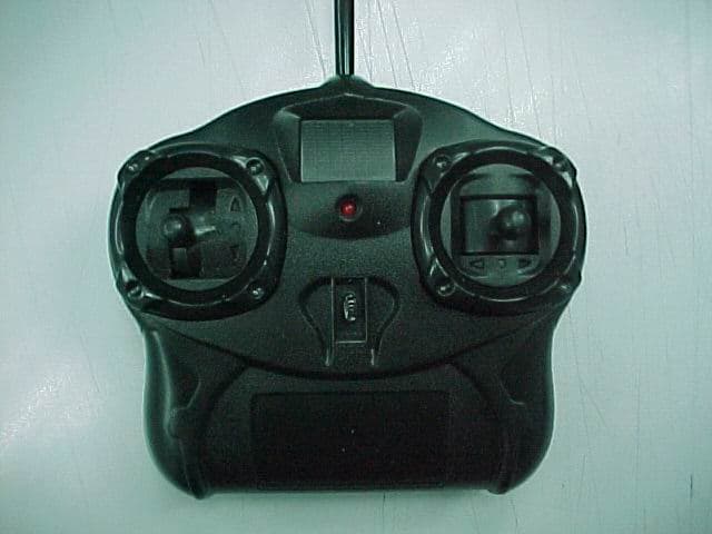
F5J21727
May 02, 200527 MHz Remote Control TX
Equipment Class
DXX - Part 15 Low Power Communication Device Transmitter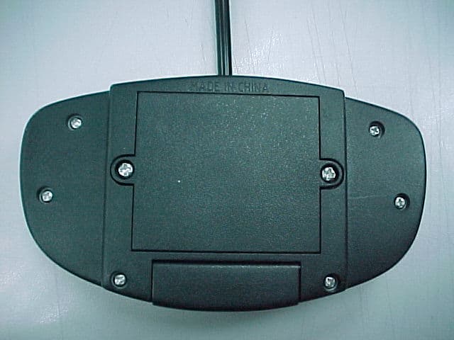
F5J99549
Jan 06, 200549MHz R/C TX
Equipment Class
DXX - Part 15 Low Power Communication Device Transmitter