FB9FPD1520LCD Monitor
Unison Electric Co Ltd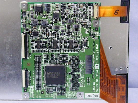
Click to zoom
Application Details
- Equipment Class
- JBP - Part 15 Class B Computing Device Peripheral
- Date of Grant
- Sep 20, 2001
- Application Purpose
- Original Equipment
- Date of Application
- Jun 05, 2000
- Equipment Note
- LCD Monitor
- Company
- Unison Electric Co Ltd
- Country
- Taiwan
Documents & Files
Document Text
Text extracted from the exhibit documents filed with the FCC. Open a document above to read the original.
Users Manual
- 0 - User Manual Cheng Uei Precision Industry Co., LTD. M atrix LCD Flat Panel D isp lay C olor M oni or 15 inch Active-Matrix LCD Flat Panel Display Color Monitor with OSD ••••• Thank you for buying our product.Please read thoroughly this user manualbefore using. After reading, keep it securely. - i - ••••• User Manual 15 •••••••••••••• 15 inch Active - Matrix LCD Flat Panel Display Color Monitor with OSD •• FPD1510XXX FoxVision FV5XX ••••••••••••••••••••••••••••••••••••••••••••••••••••••••••••••••• ” ••••• ” • •••••••••• •••••••••••••••••••••••• Table of Contents ••• - ii - 1. Safety and Regulation Information •••• .............. 1 2. Model Type and Installation ••••• ..................... 2 3. Factory Preset Timing •••• ............................... 3 4. Panel Controls and OSD Functions ••••••• ...... 4 5. Brightness/Contrast Controls ••/•••• ............... 5 6. OSD main menu/Phase Adjustment ••/•••• ...... 6 7. Pitch/H-center Adjustment •• / •••••• .............. 7 8. V-center Adjustment/Zoom Function •••••• ....... 8 9. Color Function/Language Selection •• / •••• ...... 9 10. Option Function •••••• ................................. 10 11. OSD Information OSD •••• .............................. 12 12. Troubleshooting •••• ..................................... 13 13. Specifications •••• ........................................ 15 14. Warranty Registration Card ••••• .................... 16 - 1 - •••• Safety and Regulatory Information •••••••••••••••••••••••••••••••••••••••••••••••••••••••••••••••••WarningTo prevent fire or shock hazard, do not e xpose the unit to rain or moisture. Dangerously high voltages are present inside the unit. Do not disassemble the unit. Refer servicing toqualified personnel only.•••• – ••••••••••••••••••••••••••••••••••••••••••••••••••••••••••••••••FCC NoticeThis equipment has been tested and found to comply with the limits for a Class B digital device, pursuant to Part 15 of theFCC Rules. These limits are designed to provide reasonable protection against harmful interference in a residentialinstallation. This equipment generates, uses, and can radiate radio frequency energy and, if not installed and used inaccordance with the instructions, may cause harmful interference to radio communications. However, this notice is not aguarantee that interference will not occur in a particular installation. If this equipment foes cause harmful interference to r adio or television reception, which can be determined by turning the equipment off and on, the user is encouraged to try one ofmore of the following measures: ••••••••••••• - Reorient or relocate the receiving antenna. •••••••• . - Increase the distance between the equipment and receiver. •••••••••••••••• . - Connect the equipment to an outlet on a circuit different from that to which the receiver is connected. - Consult the dealer or an experienced radio/TV technician •••••••••••••••••••••• . Any changes or modifications not expressly approved by the grantee of this device could void the user’s authority to operatethe device. •••••••••••••••••••••••••••• . - 2 - Installation •••• • Open the box. ................................................ •••• • Remove accessory box. ................................ ••••• • Carefully pull out the unit from box. ............. ••••••••••••• Warning: Do not grabe LCD panel when you pull out the unit. This may damage the panel.•••• : ••••••••••••••••••••••• • Set the unit on the top of a flat surface. ••••••••••• • Remove power adapter, AC power cord and I/O cable from accessory box. •••••••••• • Connect I/O cable and power the unit. ••••••••••••••••••••••• • Connect the other end of I/O cable to any video source. ••••••••••••••••• • Power on the video source first, then power on the unit. ••••••••••••••••• • EPA Energy Star. ............. Operation < 30 watts ••••••••••• 30 •• ( ••••• ) : .................................... Standby < 1 watts ••••••••••• 1 •• ( ••••• ) - 3 - Factory Preset Timing for Reference ••••••••••• • Note: *. Panel factory recommended operation timing. * •••••••• • Note: **. Not recommend for a normal operation. ** ••••••••••••• Resolution ••• H . Freq. (KHz) •••• V. Freq. (Hz) •••• Scan Type •••• ( • / ••• ) Pixel Freq. •••• (MHz) 640 x 350 31.469 70 Non-interlaced 25.175 720 x 400 31.469 70 Non-interlaced 28.322 640 x 400 24.83 56 Non-interlaced 21.053 640 x 480 31.469 60 Non-interlaced 25.175 640 x 480 35.000 66.67 Non-interlaced 30.24 640 x 480 37.861 72 Non-interlaced 31.50 640 x 480 37.500 75 Non-interlaced 31.50 800 x 600 37.879 60 Non-interlaced 40.00 800 x 600 48.077 72 Non-interlaced 50.00 800 x 600 46.875 75 Non-interlaced 49.50 836 x 624 49.715 74.536 Non-interlaced 57.272 960 x 720 44.80 60 Non-interlaced 56.00 *1024 x 768 48.363 60 Non-interlaced 65.00 1024 x 768 56.476 70 Non-interlaced 75.00 1024 x 768 60.023 75 Non-interlaced 78.75 - 4 - Panel Controls and OSD Functions ••••• OSD •••••• Controls •••••• Description •••• Power On/Off switch•••••• Soft power on/off button. Adjacent LED is lit when on.••••••• . ••••••••••••••••••• OSD buttonOSD •••• Press to access to OSD Main Menu and save the setting (if any).• OSD •••••••••••••••••••••••• Contrast/Adjust button•••••• To increase or decrease the panel back light luminance.••••••••••••••• OSD •••••••••• Brightness/Adjust button•••••• To increase or decrease display brightness.••••••••••••••• OSD •••••••••• Auto•••••• Auto-synchronize and scale down display to any valid factory preset timings.•••••••••••••••••••••••••• Power Indicator ••••• • GREEN ( •• ) ................................................... ON •••••• • ORANGE ( •• )................................................... ST ANDBY ••• • ORANGE ( •• )................................................... SUSPEND ••• • ORANGE ( •• )................................................... OFF •••••• Note : 1. OSD – On Screen Display •••••••••• 2. Energy Star - Leave your device power always on s…
Text truncated - open the document above for the full version.
Block Diagram
CLK68MHz DB-15VIDEO IN ADC ZOOM ENGINE LCD PANEAL SYNCPROCESSOR 12MHz MICRO CONTROLLER 20MHz FLASH ROM REMOTE KEYBOARD POWER ADAPTOR DC/DCCONVERTER Cheng Uei Precision Industry Co.,Ltd.Title: BLOCK DIAGRAM FOR FPD1520;1510April 26,2000 REV 2.0
External Photos
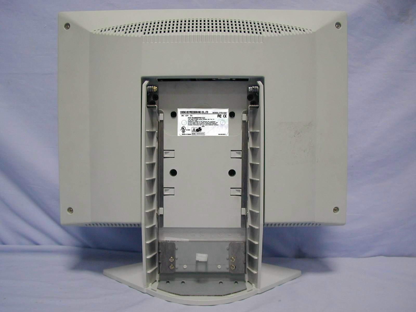
FB9D010 PHOTO OF EUT Rear View of EUT Front V iew of EUT Model : FPD-1520 FB9D010 PHOTO OF EUT Front View of EUT Rear View of EUT Model : FPD-1510 FB9D010 PHOTO OF EUT Inside View of EUT Model : FPD-1520 FB9D010 PHOTO OF EUT Inside View of EUT Model : FPD-1510 FB9D010 PHOTO OF EUT Case Inside View 1 of EUT Case Inside View 2 of EUT Model : FPD-1520 FB9D010 PHOTO OF EUT Inside View 1 of Pannel Inside View 2 of Pannel Model : FPD-1520 FB9D010 PHOTO OF EUT Front View of Pannel Rear View of Pannel Model : FPD-1520 FB9D010 PHOTO OF EUT Component Side View of LCD Board Model : FPD-1520 FB9D010 PHOTO OF EUT Case Inside View 1 of Pannel Case Inside View 2 of Pannel Model : FPD-1520 4 1 2 3 5 6 FB9D010 PHOTO OF EUT Main Board Component Side V iew of EUT Main Board Solder Side View of EUT Model : FPD-1520 FB9D010 PHOTO OF EUT Component Side View of I/O Board Solder Side View of I/O Board Model : FPD-1520 FB9D010 PHOTO OF EUT Main Board Component Side View of Inverter Main Board Solder Side View of Inverter Model : FPD-1520 FB9D010 PHOTO OF EUT Main Board Solder Side View of Control Main Board Component Side View of Control Model : FPD-1520 FB9D010 PHOTO OF EUT Front V iew of Adaptor Rear View of Adaptor Model : FPD-1520 FB9D010 PHOTO OF EUT V G A Data Cable Full View of EUT Power Cable Full View of Adaptor Model : FPD-1520 7 7 8 FB9D010 PHOTO OF EUT Inside View of Adaptor Case Inside View of Adaptor Model : FPD-1520 FB9D010 PHOTO OF EUT Main Board Component Side View of Adaptor Main Board Solder Side View of Adaptor Model : FPD-1520 FB9D010 PHOTO OF EUT Ground Plate View 1 of Adaptor Ground Plate V iew 2 of Adaptor Model : FPD-1520
Test Report
HomeTek Technology Inc. FCC ID : M6EFPD1520 FB9D010 TABLE OF CONTENTS GENERAL INFORMATION ............................................................................................................................................ 2 MODIFICATION LIST ..................................................................................................................................................... 4 CONDUCTED POWER LINE TEST...............................................................................................................................5 1TEST INSTRUMENTS & FACILITIES ........................................................................................................... 5 2TEST PROCEDURE......................................................................................................................................... 5 3TEST SETUP .................................................................................................................................................... 6 4CONFIGURATION OF THE EUT.................................................................................................................... 8 5EUT OPERATING CONDITION................................................................................................................... 11 6LIMIT OF CONDUCTED POWER LINE EMISSION CLASS B :................................................................. 11 7RESULT OF CONDUCTED POWER LINE TEST........................................................................................ 12 RADIATED EMISSION TEST....................................................................................................................................... 13 1TEST INSTRUMENTS & FACILITIES ......................................................................................................... 13 2TEST PROCEDURE....................................................................................................................................... 14 3TEST SETUP .................................................................................................................................................. 14 4CONFIGURATION OF THE EUT.................................................................................................................. 15 5EUT OPERATING CONDITION................................................................................................................... 15 6LIMIT OF RADIATED EMISSION CLASS B : ............................................................................................. 15 7RESULT OF RADIATED EMISSION TEST ................................................................................................. 16 PHOTO OF FCC ID LABEL .......................................................................................................................................... 18 APPENDIX A PHOTOS OF TEST CONFIGURATION APPENDIX B PHOTOS OF EUT HomeTek Technology Inc. FCC ID : M6EFPD1520 FB9D010Page : 2 of 18 GENERAL INFORMATION 1APPLICANT: CHENG UEI PRECISION INDUSTRY CO., LTD. 2ADDRESS : No. 18, Chung Shan Rd., Tu-Cheng Industry Park, Tu-Cheng City, Taipei Hsien, Taiwan, R. O. C. 3MANUFACTURER : CHENG UEI PRECISION INDUSTRY CO., LTD. 4ADDRESS : No. 18, Chung Shan Rd., Tu-Cheng Industry Park, Tu-Cheng City, Taipei Hsien, Taiwan, R. O. C. 5MANUFACTURER : TAIWAN VIDEO & MONITOR CORP. 6ADDRESS : No. 3-1, Shen-Keng, Peishan Li, Kuanhsi, Shinchu Taiwan, R. O .C. 5DESCRIPTION OF EUT : EUT:LCD Monitor FCC ID:M6EFPD1520 Model Number:FPD1520 Serial #:N/A Data Cable:SHIELDED Power Cord (AC)UN-SHIELDED Power Cord (DC):SHIELDED Power Supply Type:SWITCHING ADAPTOR 5.1 The EUT were investigated with three test modes: ( • )1024 x 768 ( • )800 x 600 ( • )640 x 480, and the worst case of three modes is mode ( • )1024 x 768. And the final test data of this report were shown with this test mode. HomeTek Technology Inc. FCC ID : M6EFPD1520 FB9D010Page : 3 of 18 6FEATURES OF EUT : • LCD panel:15” or 15.1” AM TFT • Input signal format:RGB analog video • Frequency:FH 30Khz-70Khz, FV50hz-85hz • Maximum Resolution:1024 (H) x 768 (V) Audio option: • Output power :2.5W per channel • Frequency response:40-20Khz • Input impedance:10K Ohm HomeTek Technology Inc. FCC ID : M6EFPD1520 FB9D010Page : 4 of 18 MODIFICATION LIST THE FOLLOWING ACCESSORIES WERE ADDED TO THE EUT DURING TESTING : ItemDescriptionManufacture Spec./ Model No. Dimension Q’tyLocationReference 1 EMI Absorbing Plate Taiwan Tokin K4E10 x 4 cm 1 Shielding Plate and LCD Signal Cable Appendix B Page 6 2 EMI Absorbing Plate Taiwan TokinK4E3.5 x 2 cm 2 Shielding Plate and LCD Signal Cable Appendix B Page 6 3 EMI Absorbing Plate Taiwan TokinK4E3 x 2 cm 2 Shielding Plate and LCD Signal Cable Appendix B Page 6 4 Conductive Fabric Tape Jong ChanCFT-0123 x 12 cm 1 LCD Signal Cable Appendix B Page 6 5 Conductive Fabric Tape Jong ChanCFT-0122.5 x 12 cm 1 LCD Signal Cable Appendix B Page 6 6 Clip-On Mounting Tenn Max187RF2C070 10 cm 1 Shielding Plate Appendix B Page 6 7 CoreErocRH17.5 x 28.5 x 9.5 mm 2 Both Side of VGA Cable Appendix B Page 13 8 CoreErocA12RH14.2 x 28.5 x 8.2 mm 1 Power Supply DC Cable Appendix B Page 13 HomeTek Technology Inc. FCC ID : M6EFPD1520 FB9D010Page : 5 of 18 CONDUCTED POWER LINE TEST 1TEST INSTRUMENTS & FACILITIES The following test Instruments was used during the conducted test : Item Instruments/ Facilities SpecificationManufacturerModel # Date Of Cal. 1EMI Receiver9KHz ~ 30MHz ROHDE & SCHWARZ ESHS 30MAR/2000 2LISN 50 • /50uH/100A 9KHz ~ 30MHz SCHWARZ BECK NNLK 8121 MAR/2000 3LISN9KHz ~ 30MHz ROHDE & SCHWARZ ESH3-Z5MAR/2000 4ESXS-K1Version 2.03b ROHDE & SCHWARZ 1082.9678.02 840.913/246 N/A 5Cables10KHz ~ 30MHz NO : 10 JUL/99 2TEST PROCEDURE 2.1 The EUT was tested according to ANSI C63.4 - 1992 & CISPR 22 . 2.2 The EUT was placed 0.4 meter from the conducting wall of shielding room and kept at least 0.8 meter from any other grounded conducting surface. 2.3 The frequency range form 0.…
Text truncated - open the document above for the full version.
Test Setup Photos
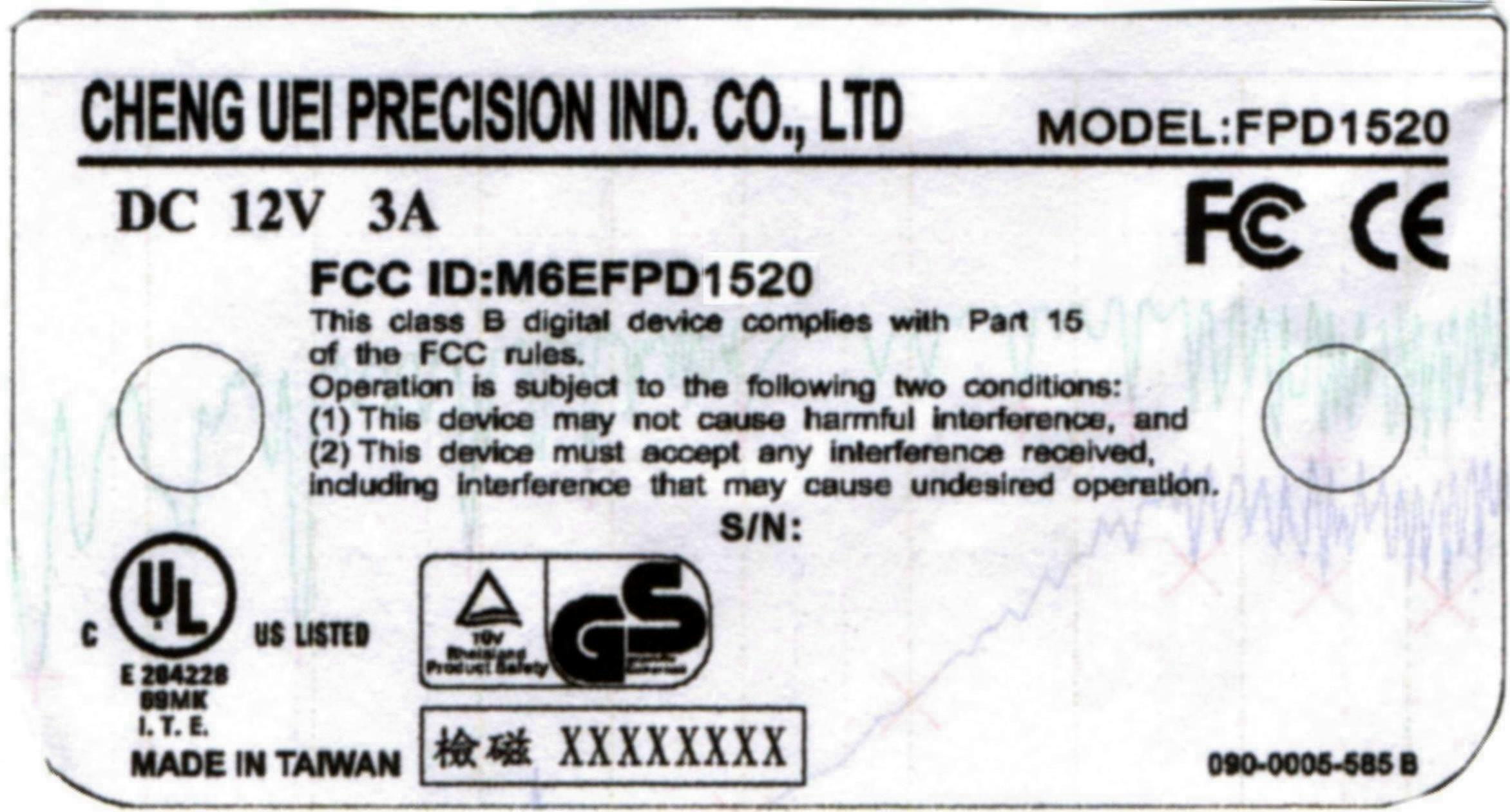
FB9D010 PHOTO OF CONDUCTED POWER LINE TEST Rear V iew Front V iew Test Mode : 1024 x 768 FB9D010 Front V iew Rear V iew PHOTO OF RADIATED EMISSION TEST Test Mode : 1024 x 768 FB9D010 FCC ID Label Location
Contact Information
Applicant
Terry Chang(Chief of Production Div.)
Technical Contact
HomeTek Technology Inc.Grant Huang
1515 Emperor Way · Taipei Hsien, California · United States
Non-Technical Contact
HomeTek Technology Inc.Chu-Lin Chu
[email protected]408-7201661
Test Firm
Home Tek Technology Inc.Grant Huang
Technical Specifications
| # | Rule Parts | Frequency Range | Power Output |
|---|---|---|---|
| 1 | 15B | - | - |
Other Applications from Unison Electric Co Ltd
FB9UBS40S
May 10, 1993Electronic Ballast
Equipment Class
8CC - Part 18 Consumer Device