FEF-453-8050RCOM-100 SatPhone
Arnav Systems Inc
Click to zoom
Application Details
- Equipment Class
- TNB - Licensed Non-Broadcast Station Transmitter
- Date of Grant
- May 07, 2003
- Application Purpose
- Original Equipment
- Date of Application
- Jan 17, 2003
- Equipment Note
- RCOM-100 SatPhone
- Frequency Range
- 1610.00000000 - 1621.35000000
- Company
- Arnav Systems Inc
- Country
- United States
Documents & Files
Document Text
Text extracted from the exhibit documents filed with the FCC. Open a document above to read the original.
Users Manual
ARNAV Systems, Inc. 16923 Meridian East Puyallup, WA. 98375 Pilot Operations Handbook for ARNAV SYSTEMS, INC. RCOM-100 Satellite Telephone Cessna 180 Series Aircraft 16 January 2003 Document No. 572-8050B ARNAV Systems, Inc. RCOM-100 Pilot Operations Handbook Document 572-8050B 2 1/16/03 Introduction The ARNAV Systems, Inc. RCOM-100 is a Globalstar satellite telephone system. The RCOM- 100 interfaces with telephone handsets or aviation equipment with a standard “POTS” (Plain Old Telephone Service) interface. This interface is sometimes called a “Tip/Ring” interface. Any compatible telephone handset can interface with the RCOM-100, but in an airplane it must be used with aviation-approved equipment. The equipment in the Cessna, Model 180 aircraft includes an NAT PTA-12 POTS Telephone Adapter that is interfaced with a UPSAT SL15 Audio Panel. The controls on the audio panel can be used to answer an incoming phone call, but the PTA-12 must be used in conjunctions with the audio panel to make a phone call. The RCOM-100 handles the communication with the ground based telecommunications network in a fully automatic method. The RCOM-100 simply acts like a normal telephone from the users perspective. ARNAV Systems, Inc. RCOM-100 Pilot Operations Handbook Document 572-8050B 3 1/16/03 Systems Description Audio Panel The audio panel is used to interface cockpit or cabin headsets and microphones to the telephone system. The SL15 audio panel has a “TEL” position on its selection switch that connects the audio channels to the “Tip/Ring” telephone interface that is tied to the RCOM-100. The audio panel controls can be used by themselves to answer an incoming call, but must be used in conjunction with the PTA- 12 Dialer device to make a phone call or to keep a phone call active while changing audio panel selections. PTA-12 POTS Telephone Adaptor (Dial Device) The PTA-12 also connects to the “Tip/Ring” interface of the RCOM-100. The PTA-12 could optionally be wired directly to the headset/microphone system, but its primary function in the Cessna 180 equipped with the SL15 audio panel is to provide dialing capability to initiate a phone call. The PTA-12 Keypad includes the numbers 0 – 9 and the * and # keys for dialing telephone numbers. There are also control buttons – Volume Up/Down, Redial, Flash, Hold, and Hook. ARNAV Systems, Inc. RCOM-100 Pilot Operations Handbook Document 572-8050B 4 1/16/03 In this application the Volume, Hold and Flash buttons are not used. “Hook” is used to start and stop a call that is being initiated from the airplane. It is not used when answering an incoming call unless the user wants to keep the phone line connected while changing audio panel selections. The “Hook” button can be pressed after answering a call on the audio panel in order to keep the line connected to the calling party while audio panel selections are changed (for example: if a call is in progress, but the pilot needs to change the audio panel switch to “COM” or “NAV” and does not want to hang up on the caller). “Redial” is used to dial the last dialed number again. In installations where the PTA-12 audio system is used with headsets and microphones or as an AUX input to an audio panel without “Phone” capabilities, the Volume and Hold functions would be available for their normal functions. Indicator There is a “Hook Status / Ringer Active” annunciator located above the “Hook” button. The LED is off when the unit is inactive (“On-hook”) and is illuminated continuously when the unit is active (“Off-hook”). If the unit is inactive and waiting for a call the LED will FLASH to indicate an incoming call. ARNAV Systems, Inc. RCOM-100 Pilot Operations Handbook Document 572-8050B 5 1/16/03 Operations Placing a Call The RCOM-100 is part of the Globalstar network. In order to make a call on the network you MUST dial a 1 plus a full TEN-digit number. The number includes the standard area code and the seven digit local number. To dial international numbers dial the country code and full number. The RCOM-100 is taken off hook by selecting “TEL” on the audio panel select switch. After selecting “TEL” there will be a dial tone on the audio system. Press the “Hook” button on the PTA-12 and then dial 1 plus the 10-digit number. After the call is complete, press, “Hook” on the PTA- 12 and move the audio panel select switch to any position other than “TEL”. Both the audio panel selector and the “Hook” switch on the dialer must be off or the phone is still off hook (has not hung up). Receiving a Call When a call comes into the RCOM-100 a ring is heard on the pilot’s headset and the “Hook / Ring Status” LED on the PTA-12 will flash. The call is answered by selecting “TEL” on the audio panel. The PTA-12 controls are not needed to answer an incoming call, but the “Hook” switch can be activated in order to keep the line connected while making different selections on the audio panel. ARNAV Systems, Inc. RCOM-100 Pilot Operations Handbook Document 572-8050B 6 1/16/03 To hang up an incoming call just select something other than “TEL” on the audio panel and pressing “Hook” on the dialer if it has been pressed to hold the line open.
Users Manual
ARNAV Systems, Inc. 16923 Meridian East Puyallup, WA. 98375 Pilot Operations Handbook for ARNAV SYSTEMS, INC. RCOM-100 Satellite Telephone Cessna 180 Series Aircraft 28 April 2003 Document No. 572-8050C ARNAV Systems, Inc. RCOM-100 Pilot Operations Handbook Document 572-8050C 2 4/28/03 Introduction The ARNAV Systems, Inc. RCOM-100 is a Globalstar satellite telephone system. The RCOM- 100 interfaces with telephone handsets or aviation equipment with a standard “POTS” (Plain Old Telephone Service) interface. This interface is sometimes called a “Tip/Ring” interface. Any compatible telephone handset can interface with the RCOM-100, but in an airplane it must be used with aviation-approved equipment. The equipment in the Cessna, Model 180 aircraft includes an NAT PTA-12 POTS Telephone Adapter that is interfaced with a UPSAT SL15 Audio Panel. The controls on the audio panel can be used to answer an incoming phone call, but the PTA-12 must be used in conjunctions with the audio panel to make a phone call. The RCOM-100 handles the communication with the ground based telecommunications network in a fully automatic method. The RCOM-100 simply acts like a normal telephone from the users perspective. ARNAV Systems, Inc. RCOM-100 Pilot Operations Handbook Document 572-8050C 3 4/28/03 Systems Description Audio Panel The audio panel is used to interface cockpit or cabin headsets and microphones to the telephone system. The SL15 audio panel has a “TEL” position on its selection switch that connects the audio channels to the “Tip/Ring” telephone interface that is tied to the RCOM-100. The audio panel controls can be used by themselves to answer an incoming call, but must be used in conjunction with the PTA- 12 Dialer device to make a phone call or to keep a phone call active while changing audio panel selections. PTA-12 POTS Telephone Adaptor (Dial Device) The PTA-12 also connects to the “Tip/Ring” interface of the RCOM-100. The PTA-12 could optionally be wired directly to the headset/microphone system, but its primary function in the Cessna 180 equipped with the SL15 audio panel is to provide dialing capability to initiate a phone call. The PTA-12 Keypad includes the numbers 0 – 9 and the * and # keys for dialing telephone numbers. There are also control buttons – Volume Up/Down, Redial, Flash, Hold, and Hook. ARNAV Systems, Inc. RCOM-100 Pilot Operations Handbook Document 572-8050C 4 4/28/03 In this application the Volume, Hold and Flash buttons are not used. “Hook” is used to start and stop a call that is being initiated from the airplane. It is not used when answering an incoming call unless the user wants to keep the phone line connected while changing audio panel selections. The “Hook” button can be pressed after answering a call on the audio panel in order to keep the line connected to the calling party while audio panel selections are changed (for example: if a call is in progress, but the pilot needs to change the audio panel switch to “COM” or “NAV” and does not want to hang up on the caller). “Redial” is used to dial the last dialed number again. In installations where the PTA-12 audio system is used with headsets and microphones or as an AUX input to an audio panel without “Phone” capabilities, the Volume and Hold functions would be available for their normal functions. Indicator There is a “Hook Status / Ringer Active” annunciator located above the “Hook” button. The LED is off when the unit is inactive (“On-hook”) and is illuminated continuously when the unit is active (“Off-hook”). If the unit is inactive and waiting for a call the LED will FLASH to indicate an incoming call. ARNAV Systems, Inc. RCOM-100 Pilot Operations Handbook Document 572-8050C 5 4/28/03 Operations Placing a Call The RCOM-100 is part of the Globalstar network. In order to make a call on the network you MUST dial a 1 plus a full TEN-digit number. The number includes the standard area code and the seven digit local number. To dial international numbers dial the country code and full number. The RCOM-100 is taken off hook by selecting “TEL” on the audio panel select switch. After selecting “TEL” there will be a dial tone on the audio system. Press the “Hook” button on the PTA-12 and then dial 1 plus the 10-digit number. After the call is complete, press, “Hook” on the PTA- 12 and move the audio panel select switch to any position other than “TEL”. Both the audio panel selector and the “Hook” switch on the dialer must be off or the phone is still off hook (has not hung up). Receiving a Call When a call comes into the RCOM-100 a ring is heard on the pilot’s headset and the “Hook / Ring Status” LED on the PTA-12 will flash. The call is answered by selecting “TEL” on the audio panel. The PTA-12 controls are not needed to answer an incoming call, but the “Hook” switch can be activated in order to keep the line connected while making different selections on the audio panel. ARNAV Systems, Inc. RCOM-100 Pilot Operations Handbook Document 572-8050C 6 4/28/03 To hang up an incoming call just select something other than “TEL” on the audio panel and pressing “Hook” on the dialer if it has been pressed to hold the line open. Safety Issues Radio Frequency Energy Your RCOM-100 incorporates a radio transmitter, receiver, and antenna that receive and send radio frequency (RF) energy. The design of the ARNAV RCOM-100 unit complies with the updated (1992) ANSI standard for safe levels of human exposure to RF energy. The minimum separation distance between the RCOM-100 antenna and the user or bystander is 38.69 cm (15.2 inches). The antenna is designed to mount on top of an aircraft fuselage. It is inherent in the mounting configuration and use of the RCOM- 100 antenna that the minimum separation distance will be maintained or exceeded under all operational conditions. ARNAV Systems, Inc. RCOM-100 Pilot Operations Handbook Document 572-8050C 7 4/28/03 Compliance with Regulations The RCOM-100 components comply with the following standards: …
Text truncated - open the document above for the full version.
Cover Letter(s)
EXHIBIT 3 CERTIFICATION OF TEST DATA The data, data evaluation, and equipment configuration presented herein are a true and accurate representation of the measurements of the sample’s radio frequency interference emissions characteristics as of the date and at the time of the tests under the test conditions specified herein. This applies to all test that were performed that did not require an Open Area Test/Site (OATS). Test that required an OATS were performed by TUV Product Services, with an office out of the San Diego area. Qualcomm’s Paul Jayne witnessed the tests. Equipment Tested: RCOM-100 SatPhone, S/N: 805003 Sincerely, DeLyle Danner R & D Manager
Cover Letter(s)
TO: Stan Lyles [email protected] FCC Application Processing Branch FROM: DeLyle Danner, ARNAV Systems, Inc. PAGES: 2 RE: FCC ID FEF-453-8050 APPLICANT: ARNAV Systems, Inc. Correspondence Reference Number: 24834 731 Confirmation Number: EA851428 In response to the correspondence received on 2/21/03, the following information has been provided. 1) Based on your test reports we cannot determine the frequency range for this device. The Exhibit 4b Radiated Spurious Emissions page 9 addresses this. Page 9 has been copied and will be part of this memo. Frequency band of operation is over channels 6-9: 1616.255 MHz (lowest channel 6 center frequency – 0.5BW; 1616.88-0.625 = 1616.255 MHz) to 1621.35 MHz (which is the upper frequency allocated to CDMA MSS, includes some guard band to Iridium assigned band). 2) Please submit RF output power measurements data for low, middle, and high bands per Section 2.1046. This information is contained on page 9 of Exhibit 4b that will be part of this memo. 3) Please submit the transmitter schematics for this device. Schematics and parts lists have been included as Exhibits 15-19. 4) Please submit internal photos for this device. Internal photos have been submitted by Exhibit 20. Just to reiterate this is a Part 25 submission with a designator of 1M25G1W. An additional Request for Confidentiality Letter Exhibit 2A to cover Exhibits 15-20 was also posted. Exhibit 2 is still valid. ARNAV Systems, Inc. is under non-disclosure with Qualcomm on these Exhibits. ARNAV Systems would hope that the FCC would honor this confidentiality as they did with Qualcomm’s filing of the exact same information.
Cover Letter(s)
EXHIBIT 2B Federal Communications Commission Reference: FCC ID: FEF-453-8050 Request for Confidentiality Pursuant to Sections 0.457 – 0.459 of the Commission’s rules, ARNAV Systems, Inc. hereby requests confidentiality for certain aspects of the information accompanying the Application for Certification. The following exhibits show be classified as confidential. • Exhibit 10 – Antenna • Exhibit 11 – Power Supply Schematics • Exhibit 12 – Spine Board Assembly Drawing • Exhibit 12a – Spine Schematic • Exhibit 15 – Parts List – CCA, RF, Production, GS Fixed Phone (#20- 81680 REV B) • Exhibit 16 – Parts List – CCA, Digital, RAU W/DataPort (AFUT) (#20- 81220-1 REV F) • Exhibit 17 – CCA, RF, Production, GS Fixed Phone (LD20-81680 REV-) • Exhibit 18 – Schematic – CCA, Digital, RAU (LD20-81220 REV A) • Exhibit 19 – Drawing – CCA, Borscht Only Card (REN) (CV90-70767 REV A) All items contain trade secrets and other proprietary information not customarily released to the general public. Public disclosure of this information would be harmful to ARNAV Systems, Inc., and Qualcomm incorporated at this time, and would provide unjustified benefits to our competitors. These materials contain proprietary intellectual property that Qualcomm is in the process of filing for patent protection. ARNAV understands that, pursuant to Rule 0.457, disclosure of any information contained in this application will not be made before the date of the grant. Sincerely, DeLyle Danner R & D Manager ARNAV Systems, Inc
Cover Letter(s)
TO: Stan Lyles [email protected] FCC Application Processing Branch FROM: DeLyle Danner, ARNAV Systems, Inc. PAGES: 1 RE: FCC ID FEF-453-8050 APPLICANT: ARNAV Systems, Inc. Correspondence Reference Number: 25098 731 Confirmation Number: EA851428 In response to the correspondence received on 4/25/03, the following information has been provided. 1) In response to confidentiality request of items 1-3 a new confidentiality letter Exhibit 2B, which supercedes the other 2 confidentiality letters, has been submitted. 2) Occupied bandwidth plots and spectrum mask plots of the fundamental frequency have been submitted as Exhibit 21 in response to item 4. 3) The Pilots Operating Handbook, Exhibit 8A, and Installation Guide, Exhibit 9A, have both been updated with the RF exposure information as requested in item 5. Note that the updated manuals supercedes the previous revisions. 4) The frequency tolerance on from 731 should be 10ppm to clarify item 6. I’m unable to edit the 731 form to make the change. 5) The RF Exposure, Exhibit 5, has been updated to Exhibit 5A.
Cover Letter(s)
TO: Stan Lyles [email protected] FCC Application Processing Branch FROM: DeLyle Danner, ARNAV Systems, Inc. PAGES: 1 RE: FCC ID FEF-453-8050 APPLICANT: ARNAV Systems, Inc. Correspondence Reference Number: 25098 731 Confirmation Number: EA851428 In response to the correspondence received on 4/25/03, the following information has been provided. 1) In response to confidentiality request of items 1-3 a new confidentiality letter Exhibit 2B, which supercedes the other 2 confidentiality letters, has been submitted. 2) Occupied bandwidth plots and spectrum mask plots of the fundamental frequency have been submitted as Exhibit 21 in response to item 4. 3) The Pilots Operating Handbook, Exhibit 8A, and Installation Guide, Exhibit 9A, have both been updated with the RF exposure information as requested in item 5. Note that the updated manuals supercedes the previous revisions. 4) The frequency tolerance on from 731 should be 10ppm to clarify item 6. I’m unable to edit the 731 form to make the change. 5) The RF Exposure, Exhibit 5, has been updated to Exhibit 5A.
ID Label/Location Info
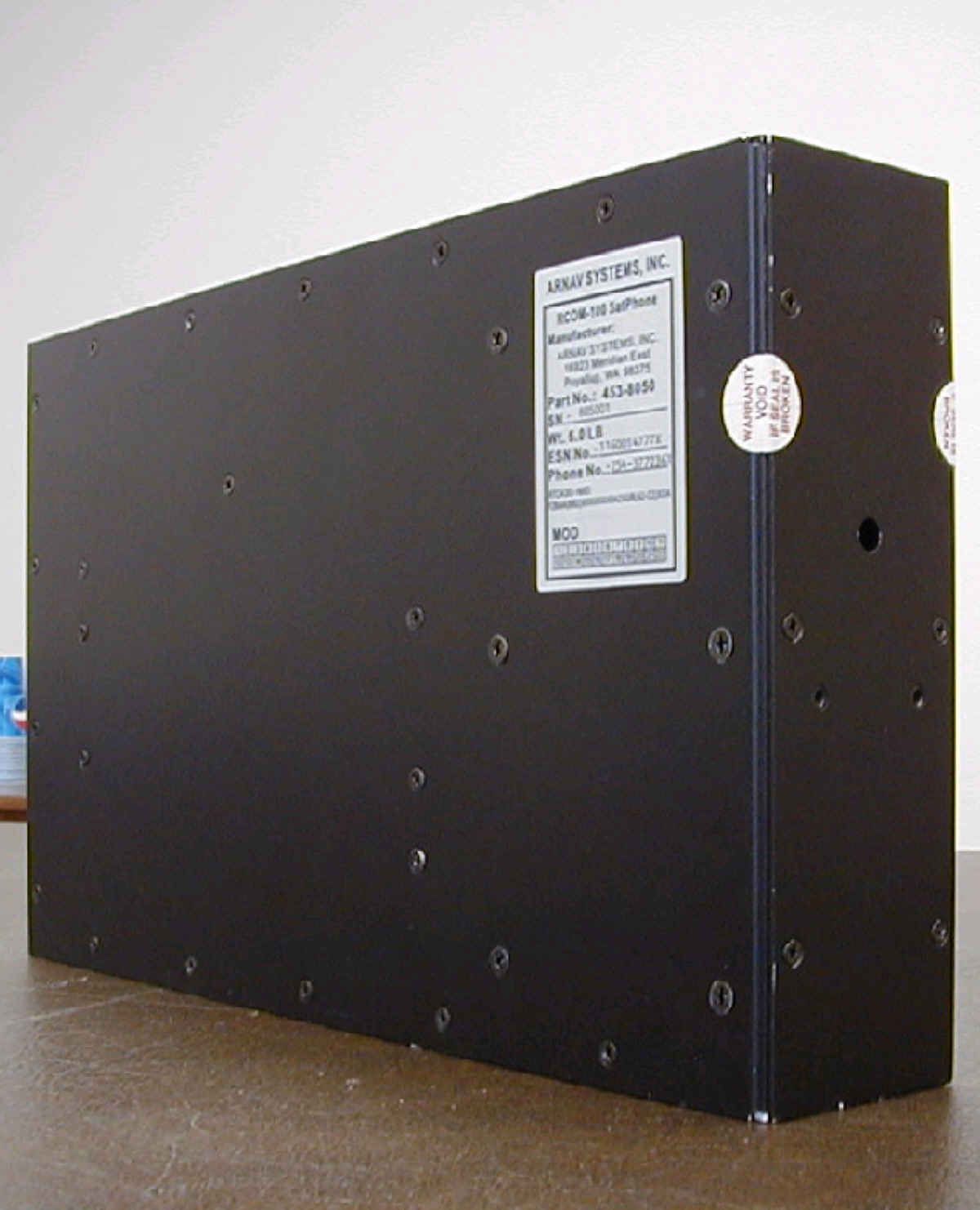
1.93 R.06 TYP. 2.48 .125 TYP. TYP. .10 .30 .10 2.13 2.45 2.88 22 11 21 10 20 19 98 18 7 17 16151413 6 5 4 3 2 1 12 0.06 HIGH CHARACTERS 0.03 WIDE LINE ALL AROUND FULL SCALE NOTEs: 1. MATERIAL: .002 SILVER BRUSHED MYLAR. 2. ARTWORK PROVIDED BY ARNAV. 3. CHARACTERS AND LINES: HOT STAMPED, BLACK. 4. LABELS TO BE PROVIDED IN ROLL FORM, ORIENTATED WITH TOP OF LABEL TOWARD OPEN END OF ROLL. ARNAV SYSTEMS, INC. CAD GENERATED DRAWING, DO NOT MANUALLY UPDATE SCALE SIZE CAD FILE: DWG. NO. A SHEET OF REV DATE APPROVALS DRAWN CHECKED PROJ ENGR ISSUED UNLESS OTHERWISE SPECIFIED DIMENSIONS ARE IN INCHES TOLERANCES ARE: DECIMALS ANGULAR ..XX.010 .XXX.OO5 .XXXX.0010 MATERIAL FINISH -- DO NOT SCALE DRAWING THE INFORMATION CONTAINED IN THIS DRAWING IS THE SOLE PROPERTY OF ARNAV SYSTEMS, INC. ANY REPRODUCTION IN PART OR WHOLE WITHOUT THE WRITTEN PERMISSION OF ARNAV SYSTEMS, INC. IS PROHIBITED. REV DESCRIPTION REVISIONS DATE APPROVED - ORIGINAL RELEASE 01/17/02 JR 12/18/02 16923 MERIDIAN EAST PUYALLUP, WA 98373 LABEL, PRODUCT RCOM - 100 591-4529 11 .5 TITLE NOTED B GH 2:1 A ECO-4608 2/12/02GH ECO-4625 12/18/02 B
Internal Photos
1 2 3 4 5 7 8 9 10 11 12 13 14 15 16 17 18 19 21 21 29 29 20 20 20 22 22 6 23 24 25 22 26 28 27 30 31 32 33 34 35 30 19 37 ASSEMBLY NOTES: 1. ASSEMBLE ACCORDING TO MANUFACTURE OUTLINE AFTER COMPLETING ENG-1484 AS PER ENG-7051. 2. FREE END OF ITEM 1 CONNECTS TO ITEM 3. 3. FREE END OF ITEM 4 CONNECTS TO ITEM 31. 4. FREE END OF ITEM 5 CONNECTS TO ITEM 2. 5. FREE END OF ITEM 2 CONNECTS TO ITEM 33, J6. 6. FREE END OF ITEM 3 CONNECTS TO ITEM 33, J4. 7. FREE END OF ITEM 34 CONNECTS TO ITEM 33, J1. 8. FREE END OF ITEM 35 CONNECTS TO ITEM 33, J5. 9. INSTALL ANTI-STATIC TAPE OR ANTI-STATIC CAPS ON EXTERNAL CONNECTORS. 36 CAD GENERATED DRAWING, DO NOT MANUALLY UPDATE SCALE SIZE CAD FILE: DWG. NO. B SHEET1OF1 REV. RCOM-100 MAIN ASS'Y. DATE APPROVALS DRAWN CHECKED PROJ ENGR ISSUED UNLESS OTHERWISE SPECIFIED DIMENSIONS ARE IN INCHES TOLERANCES ARE: MATERIAL FINISH -- -- DO NOT SCALE DRAWING ITEM NO. PART OR IDENTIFYING NO. NOMENCLATURE OR DESCRIPTION REVISION QTY REQD PARTS LIST THE INFORMATION CONTAINED IN THIS DRAWING IS THE SOLE PROPERTY OF ARNAV SYSTEMS, INC. ANY REPRODUCTION IN PART OR WHOLE WITHOUT THE WRITTEN PERMISSION OF ARNAV SYSTEMS, INC. IS PROHIBITED. REVISIONS REV DESCRIPTIONDATE APPROVED ARNAV SYSTEMS, INC. 453-8050 DECIMAL .XX .010 .XXX .005 .XXXX.0010 ANGULAR .5 JR 10/01/02 12 1 16923 MERIDIAN EAST PUYALLUP, WA 98373 B ORIGINAL RELEASE A 402-3332FRONT PANEL 09/12/02 TITLE - 1TOP PANEL B 402-3330 14 1PCA, HERMES A 345-018015 1 PCA, SPINE A 345-0192 16 1 GATE A 402-3334 10 1REAR PANELB402-3333 11 1 LEFT PANEL B 402-3331 13 1RIGHT PANEL - 402-3335 9 1 FILTER, LORCH - 111-0912 29 1 CLAMP DOWN HOOK - 258-7006 18 1HANDLE - 451-0169 7 2 1 LABEL, PRODUCT, RCOM-100 B 591-4529 6 1 PLUG,PLASTIC - 263-0051 17 12 4-40 X 7/16 PHP SS W/LW -201-0407 1BOTTOM PANEL - 402-3357 8 51 4-40 X 3/16 FHP BLACK - 212-0404 21 1LABEL, TX - 591-4540 30 1 QUALCOMM PCA 81220 5 SPACER 0.250 X 0.090 - 246-1004 20 4SPACER,3/16 M/F 4-40X5/16 W/HDWR - 253-0421 19 1CABLE, RX INPUT TO GATE - 611-6107 1 - 211-0603 #6-32 X .25 FHP SS 6 23 CABLE, TX GATE INTERNAL1 - 611-6106 2 CABLE, RX GATE INTERNAL1 - 611-6105 3 CABLE, TX INPUT TO FILTER1 - 611-6104 4 CABLE, TX FILTER TO GATE1 - 611-6103 5 211-0405 24 - 4-40 X 1/4 FHP BLACK 2 4-40 X 3/16 FHP SS2 - 22 212-0403 4-40 X 1/4 PHP BLACK204-0405 26 - 4 201-0604 27 #6-32 X 1/4 PHP SS - #6-32 X 5/16 PHP BLACK - 25 204-0605 2 28 1 QUALCOMM FLEX CABLE 70832 1QUALCOMM CABLE 70992 LOCKWASHER #45 - 247-0400 201-0406 31 - 4-40 X3/8 PHP SS 5 B ECO - 4620 10/01/02 GH QUALCOMM PCA 23545 1 Table 1 452-8050 QUALCOMM KIT QTYITEM NO. DESCRIPTION 32 33 34 35 QUALCOMM KIT1 - 452-8050 SEE TABLE 1 36 37LABEL, RX 1 - 591-4541
Internal Photos
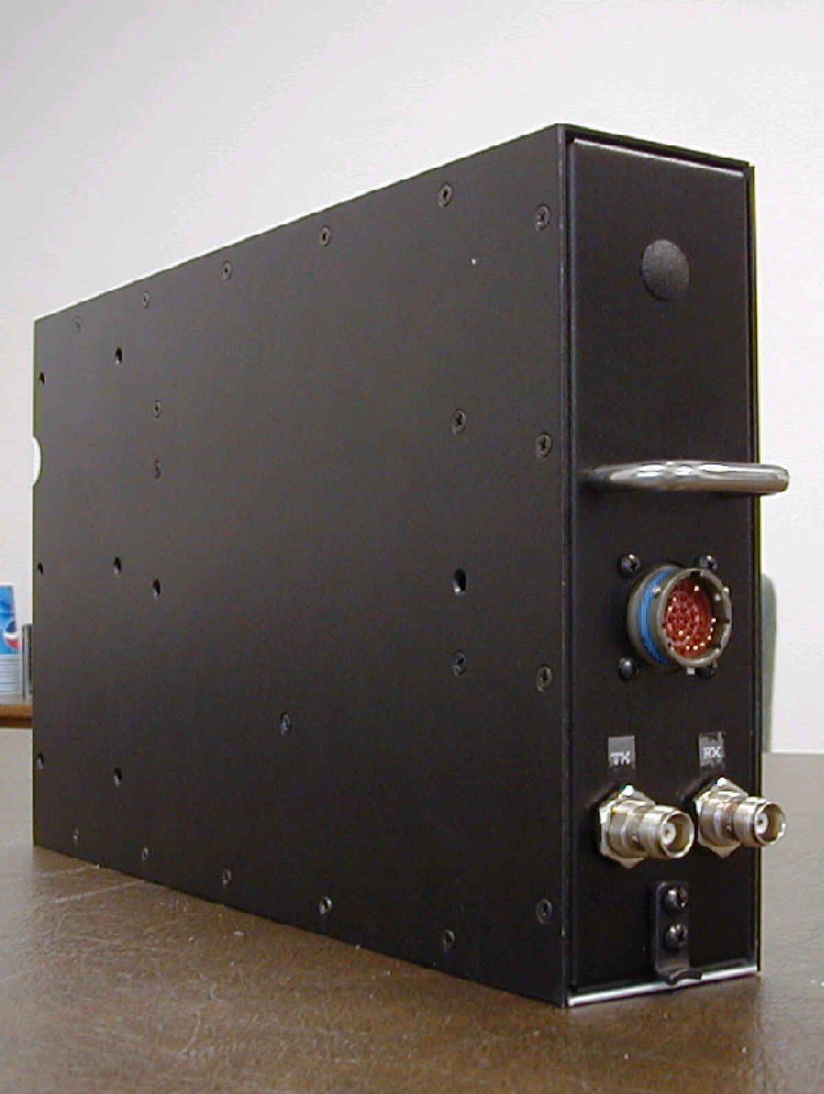
RCOM-100 FCC Part 25 Application ARNAV SYSTEMS, INC. PROPRIETARY Page 1-24 EXHIBIT 20 – INTERNAL PHOTOS OF RCOM-100 20.1 RCOM-100 EXTERNAL PICTURE OF RCOM-100 RCOM-100 FCC Part 25 Application ARNAV SYSTEMS, INC. PROPRIETARY Page 2-24 20.2 RCOM-100 OPENED RCOM-100 OPENED AND LABELED RCOM-100 FCC Part 25 Application ARNAV SYSTEMS, INC. PROPRIETARY Page 3-24 20.3 RCOM-100 RF BOARD RF BOARD RCOM-100 FCC Part 25 Application ARNAV SYSTEMS, INC. PROPRIETARY Page 4-24 RF BOARD WITH SHIELDS REMOVED RF BOARD ZOOM RCOM-100 FCC Part 25 Application ARNAV SYSTEMS, INC. PROPRIETARY Page 5-24 RF BOARD ZOOM RF BOARD ZOOM RCOM-100 FCC Part 25 Application ARNAV SYSTEMS, INC. PROPRIETARY Page 6-24 RF BOARD ZOOM RCOM-100 FCC Part 25 Application ARNAV SYSTEMS, INC. PROPRIETARY Page 7-24 RF BOARD ZOOM RF BOARD ZOOM RCOM-100 FCC Part 25 Application ARNAV SYSTEMS, INC. PROPRIETARY Page 8-24 RF BOARD ZOOM BACK OF RF BOARD RCOM-100 FCC Part 25 Application ARNAV SYSTEMS, INC. PROPRIETARY Page 9-24 20.4 RCOM-100 DIGITAL BOARD DIGITAL BOARD RCOM-100 FCC Part 25 Application ARNAV SYSTEMS, INC. PROPRIETARY Page 10-24 DIGITAL BOARD ZOOM RCOM-100 FCC Part 25 Application ARNAV SYSTEMS, INC. PROPRIETARY Page 11-24 DIGITAL BOARD ZOOM RCOM-100 FCC Part 25 Application ARNAV SYSTEMS, INC. PROPRIETARY Page 12-24 20.5 BORSCHT REN CARD BORSCHT REN BOARD RCOM-100 FCC Part 25 Application ARNAV SYSTEMS, INC. PROPRIETARY Page 13-24 BORSCHT REN CARD ZOOM BORSCHT REN CARD ZOOM RCOM-100 FCC Part 25 Application ARNAV SYSTEMS, INC. PROPRIETARY Page 14-24 BORSCHT REN CARD ZOOM BACK OF BORSCHT REN CARD RCOM-100 FCC Part 25 Application ARNAV SYSTEMS, INC. PROPRIETARY Page 15-24 20.6 RCOM-100 HERMES (POWER SUPPLY) HERMES and BORSCHT REN BOARD RCOM-100 FCC Part 25 Application ARNAV SYSTEMS, INC. PROPRIETARY Page 16-24 HERMES WITHOUT BORSCHT REN ATTACHED RCOM-100 FCC Part 25 Application ARNAV SYSTEMS, INC. PROPRIETARY Page 17-24 HERMES BOARD ZOOM RCOM-100 FCC Part 25 Application ARNAV SYSTEMS, INC. PROPRIETARY Page 18-24 HERMES BOARD ZOOM RCOM-100 FCC Part 25 Application ARNAV SYSTEMS, INC. PROPRIETARY Page 19-24 HERMES BOARD ZOOM RCOM-100 FCC Part 25 Application ARNAV SYSTEMS, INC. PROPRIETARY Page 20-24 BACK OF HERMES RCOM-100 FCC Part 25 Application ARNAV SYSTEMS, INC. PROPRIETARY Page 21-24 ZOOM OF HERMES BACK RCOM-100 FCC Part 25 Application ARNAV SYSTEMS, INC. PROPRIETARY Page 22-24 20.7 SPINE BOARD SPINE BOARD RCOM-100 FCC Part 25 Application ARNAV SYSTEMS, INC. PROPRIETARY Page 23-24 BACK OF SPINE RCOM-100 FCC Part 25 Application ARNAV SYSTEMS, INC. PROPRIETARY Page 24-24 Exhibit 15 and 17 – Applicable Schematics and Parts Lists for the RF Board Exhibit 16 and 18 – Applicable Schematics and Parts Lists for the Digital Board Exhibit 19 – Drawing – CCA Borscht only Card (REN) Exhibit 11 and 11a – Hermes, Power Supply, Schematics and Part Lists Exhibit 12 and 12a – Spine Schematics and Part Lists
Operational Description
ARNAV Systems, Inc. 16923 Meridian East P.O. Box 73730 Puyallup, Washington 98375 (253) 848-6060 RCOM-100 Installation GUIDE PART NUMBER 570-8050B 27 November 2002 Proprietary Notice The Information contained in this document is proprietary to ARNAV Systems, Inc., and shall not be reproduced or disclosed in whole or in part to persons not authorized by ARNAV. ARNAV Systems, Inc. 1 Document No. 570-8050B 27 November 2002 REVISIONS REV DESCRIPTION DATE APPROVAL - Initial Release August 2002 LAJ A Minor Changes 11/15/02 LAJ B Added Antenna Doubler 11/27/02 LAJ ARNAV Systems, Inc. 2 Document No. 570-8050B 27 November 2002 TABLE OF CONTENTS 1. INTRODUCTION..................................................................................................................................................3 2. OVERVIEW............................................................................................................................................................3 3. INSTALLATION...................................................................................................................................................4 Installation Kit:............................................................................................................................................................4 Determining Mounting Locations:...........................................................................................................................4 Table 3-1 Transmit Cable Lengths...........................................................................................................................5 Table 3-2 Receive Cable Lengths.............................................................................................................................5 Securing The Mounting Tray:...................................................................................................................................6 Transmit/Receive Antenna Installation:..................................................................................................................7 Mounting the NAT PTA-12 Dialer:.........................................................................................................................9 VC28 Mounting:........................................................................................................................................................10 Route Coax Cables for Tx and Rx:.........................................................................................................................10 Wiring the RCOM-100, VC28, PTA-12:..............................................................................................................11 Description...........................................................................................................................................................12 4. DATA PORT.........................................................................................................................................................13 Asynchronous Services:...........................................................................................................................................13 Packet Services:.........................................................................................................................................................13 5. SYSTEM TESTING..............................................................................................................................................14 ARNAV Systems, Inc. 3 Document No. 570-8050B 27 November 2002 1. INTRODUCTION The RCOM-100 is a Globalstar satellite telephone for aviation. It is housed in an ARINC 600 2 MCU enclosure. The RCOM-100 is designed to provide voice and data communication in an avionics application. The voice connection is established through a standard TIP/RING interface. The RCOM-100 can be connected to any standard telephone handset that complies with EIA/TIA-464B and TIA/EIA/IS-470-B. The data connection is through the RCOM-100 data port. The data port supports two types of data services: asynchronous data, and packet data. Asynchronous data provides the capability of establishing a connection between a device connected to the data port, and any Hayes compatible modem connected to the Public Switch Telephone Network. For packet data the device connected to the data port must be able to support a PPP session over TCP/IP. This is the typical standard used by computers for dial-up services. The installation to the RCOM-100 consists of: • Locating and mounting the transmit/receive antenna • Installation of the mounting tray for the ARINC 600 2MCU box • Locating and mounting the NAT PTA-12 Dialer • Locating and mounting the VC28 DC-to-DC converter (14 to 28 volts for PTA-12_ • Wiring the RCOM-100 37 pin circular connector for power, tip/ring, and the data connection port. • Wiring the PTA-12 to the Audio Panel. Installation Requirements: When installing the ARNAV RCOM-100 the installer must have a working knowledge of aircraft electronics installation, and be a holder of a FAA Repairman’s Certificate. All installations should meet the requirements of FAA advisory circular AC43.13-1B. 2. OVERVIEW The main tasks for this installation are listed below: 1. Check the shipped installation kit components against this manual. 2. Determine the approximate location of the RCOM-100, the transmit/receive antenna, the PTA-12, and the VC28. Factors considered for locations are minimum and maximum antenna coax lengths, and minimum GPS and transmit antenna separation. 3. Mount the ARINC 600 2 MCU tray. 4. Mount the transmit/receive antenna. ARNAV Systems, Inc. 4 Document No. 570-8050B 27 November 2002 5. Mount the PTA-12 6. Mount the VC28. 7. Route the coax cables for transmit and receive to the ARINC 600 2 MCU tray. 8. Create the wire harness for the RCOM-100 and PTA12. 9. TIP/RING voice communications check out. 3. INSTALLATION Ins…
Text truncated - open the document above for the full version.
Operational Description
ARNAV Systems, Inc. 16923 Meridian East P.O. Box 73730 Puyallup, Washington 98375 (253) 848-6060 RCOM-100 SatPhone FCC Part 25 Certification Report FCC ID: FEF-453-8050 DOCUMENT NUMBER: ENG-5027 REV - 20 January 2003 Propr…
Text truncated - open the document above for the full version.
Contact Information
Applicant
DeLyle Danner(R & D Manager)
Technical Contact
ARNAV Systems, Inc.DeLyle Danner
[email protected]253-848-6060
16923 Meridian East · Puyallup, Washington · United States
Non-Technical Contact
ARNAV Systems, Inc.Lynn A Johnson
[email protected]253-848-6060
Technical Specifications
| # | Rule Parts | Frequency Range | Power Output | Emission | Tolerance |
|---|---|---|---|---|---|
| 1 | 25 | 1.61 GHz - 1.62 GHz | 4 W | 1M25G1W | 10.0000000000 ppm |
Other Applications from Arnav Systems Inc
FEF5CO453-0125
Nov 06, 1986This unit is type accepted under the terms of the waiver issued by the Commissions Private Radio Bureau in their letter dated Oct. 30, 1986.
Equipment Class
TNB - Licensed Non-Broadcast Station Transmitter