FFW-950-12LR-HHCMobileECG
Memtec Corporation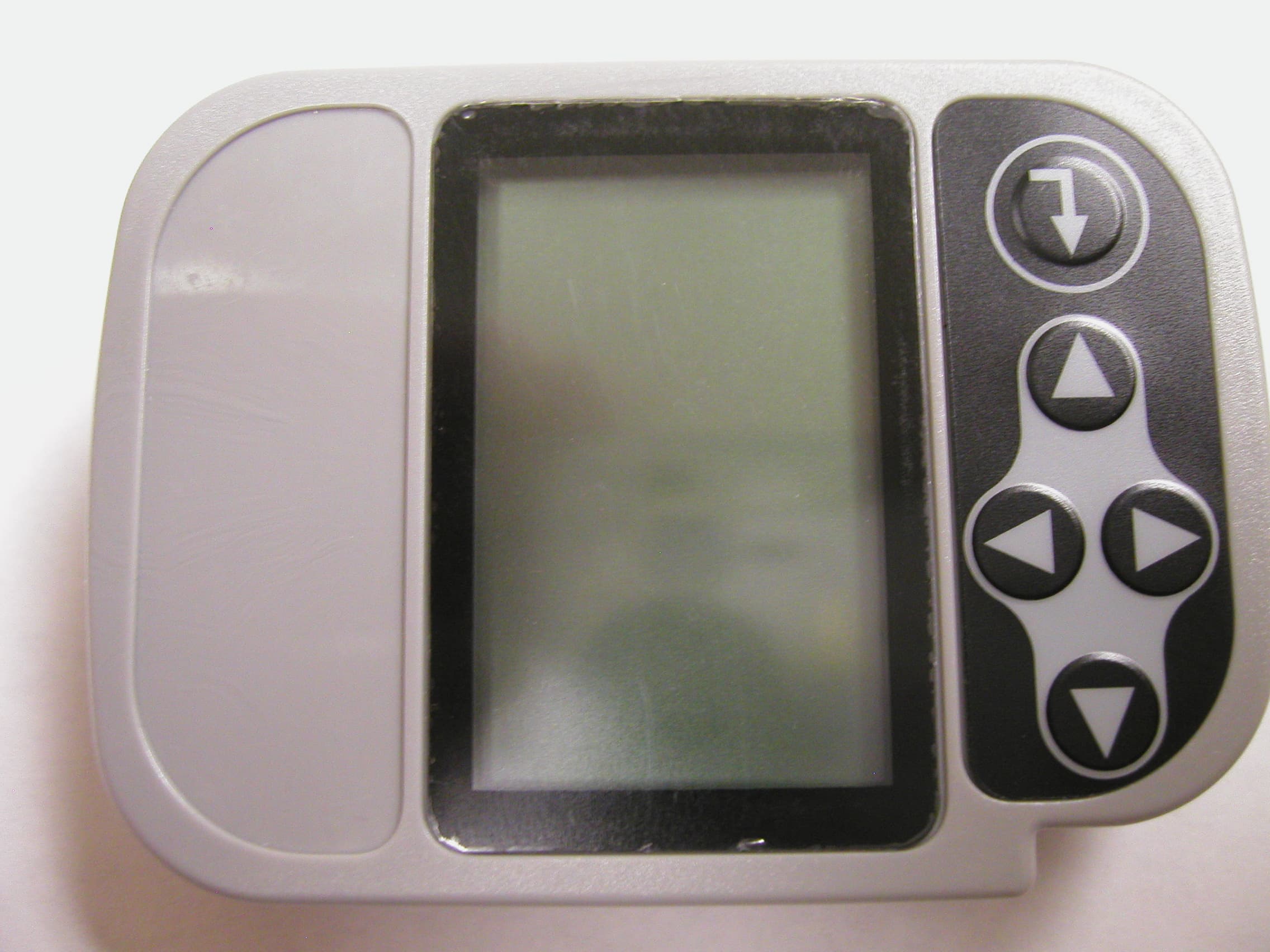
Click to zoom
Application Details
- Equipment Class
- DTS - Digital Transmission System
- Date of Grant
- Oct 03, 2010
- Application Purpose
- Original Equipment
- Date of Application
- Oct 03, 2010
- Equipment Note
- MobileECG
- Frequency Range
- 2404.80000000 - 2480.00000000
- Company
- Memtec Corporation
- Country
- United States
Documents & Files
Document Text
Text extracted from the exhibit documents filed with the FCC. Open a document above to read the original.
Users Manual
Page 1 OPERATION MANUAL MODEL 950-12LR-HHC Overview ...............................................................................................................1 Patient Hookup.....................................................................................................1 Typical Electrode Placement ................................................................................2 Cautions for the operator:..................................................................................6 Recording Procedure ............................................................................................6 Detailed Recorder Operation ................................................................................7 Recording Termination........................................................................................11 Normal Termination.........................................................................................11 Disconnect the patient electrode leads............................................................11 Retrieving Recording Data ..................................................................................11 Recorder Maintenance........................................................................................11 FCC Compliance Statement ...............................................................................11 Overview The Memtec model 950-12LR-HHC is a battery operated ECG monitoring device that provides true 12-lead, high-resolution, clinical/research-grade recordings with wireless transmission in the 2.4Ghz ISM band for ECG machine function. The device has a resolution of 12 bits, with data viewed and stored uncompressed on a PC. The data is transmitted wirelessly to a PC in real-time for use as an ECG machine. Data integrity is provided through a unique patent- pending technique that includes data, time and patient ID stamps along with a CRC-16 check on the recording every 2 minutes, ensuring usable recordings while preventing patient data mix-ups. A large LCD provides real-time patient ECG signals to confirm lead placement during patient hook-up. One “AA” alkaline battery provides power for up to a month of use. The model 950-12LR-HHC over-samples the input signal at a rate of 6,000 samples/second to support hardware pacemaker detection on all channels. Patient Hookup Once the cardiologist has specified the desired type of patient hookup, the specific location and method of attachment of the electrodes to the body is crucial to achieving the best signal. The following recommendations enable the user to obtain the highest quality signals and recording: 1. Connect the electrodes to the bony area over a rib or sternum to reduce muscle noise interference. Placing the electrode over large muscle areas or in the intercostal spaces can cause high frequency artifacts that degrade the Model 950-12LR-HCC Operation Manual Page 2 signal significantly. Electrode placement over fatty areas will also cause signal degradation. Always refer to the ANSI/AAMI Standard EC12-1991 for safety, performance, and labeling requirements for the disposable electrodes, and guidelines for reliable patient connections. 2. Any body hair around the electrode site must be removed by dry shaving. The electrode site must be thoroughly cleaned to remove surface skin oil and dirt. Use a gauze pad moistened with alcohol to properly clean the area. Gauze should be used rather than alcohol prep pads because of its superior abrasive quality. 3. The center of the electrode site where the pad of the electrode will make contact with the skin should be wiped 3 or 4 times with a small piece of extra fine sandpaper or similar abrasive material to remove the dead superficial layer of skin. This will significantly improve the electrical contact between the skin surface and the electrode to provide a quality signal. 4. Finally, proper patient hookup of all channels/leads should be thoroughly tested by using the built in hook-up review feature to verify that the appropriate amplitude signal is being obtained from each channel/lead without noise or artifacts. Typical Electrode Placement The Model 950-12LR-HHC has two major modes of operation: 1. Standard 12-Lead mode 2. Optional 3-channel mode. The cable used on the unit determines the device mode of operation. Changing the mode requires insertion of the appropriate cable. The cable options are: • 10-wire cable for 12-lead recordings • 7-wire cable for 1, 2 or 3-channel recordings The standard patient electrode connections to this device use a 12-Lead/10-Wire cable that conforms to the standard AHA electrode color code system as specified in ANSI/AAMI EC11:1991/(R)2001. See Figure 1- Hookup for 12- Lead/10-Wire. For special applications an optional cable is available to allow viewing and recording of 1, 2, or 3 individual channels. This is a seven lead cable that uses the standard AHA electrode color code system as specified in ANSI/AAMI EC13:2007. See Figure 2 - Hookup for 3-Channel 7-Wire. Model 950-12LR-HCC Operation Manual Page 3 Variations on the electrode placement sites may be chosen by the cardiologist depending on the type of arrhythmia the patient is suspected of having and other factors. 12-Lead (10-Wire) Electrode Placement Wire # Electrode Identifier Color Code Position on body 1 RA White Right arm 2 LA Black Left arm 3 LL Red Left leg 4 V1 Brown/red 4 th intercostals (IC) space at right border of sternum 5 V2 Brown/yellow 4 th IC space at left border of sternum 6 V3 Brown/green Midway between V2 and V4 7 V4 Brown/blue 5 th IC space on left midclavicular line 8 V5 Brown/orange Left anterior axillary line at the horizontal level of V4 9 V6 Brown/violet Left midaxillary line at the horizontal level of V4 10 RL Green Right leg Figure 1- Hookup for 12-Lead/10-Wire Sessions Model 950-12LR-HCC Operation Manual Page 4 3-Channel (7-Wire) Electrode Placement Wire # Channel Color Code Position on body 1 1 + Red Left anterior axillary lin…
Text truncated - open the document above for the full version.
Cover Letter(s)
MEMTEC Corporation Memtec Corporation ● 68 Stiles Road Unit D ● Salem, NH 03079 ● Tel. 603 893-8080 Fax. 6038938699 Elliott TCB 684 West Maude Ave. Sunnyvale, CA. 94085 September 3, 2010 Gentlemen: This is your letter of authorization to accept our appointment of Elliott Laboratories, Inc. as our Agent for Memtec Corporation, 68 Stiles Road Unit D, Salem, NH 03079, to sign applications before Elliott TCB and to make representations to you on our behalf. Elliott Laboratories, Inc. is to receive and exchange data between our company and Elliott TCB. I hereby certify on behalf of Memtec Corporation, 68 Stiles Road Unit D, Salem, NH 03079 "Applicant") that neither Applicant nor any party to the application (officers, directors, and 5% shareholders) is subject to a denial of Federal benefits that includes FCC benefits pursuant to section 5301 of the Anti-Drug Abuse Act of 1988. 21 U.S.C. 853a. Sincerely, Dennis P. Garboski President
Cover Letter(s)
MEMTEC Corporation Memtec Corporation●68 Stiles Road Unit D●Salem, NH 03079 Tel: 603 893-8080●Fax: 603 893-8699●Email: [email protected] September 10, 2010 Elliott TCB 41039 Boyce Road Fremont, CA. 94538 RE: Request for Confidentiality In reference to the application under FCC ID: FFW-950-12LR-HHC, and pursuant to Sections 0.457(d)1(ii) and 0.459 of the Commission’s Rules, Memtec Corporation hereby requests confidential treatment of the accompanying information as outlined below: Block Diagram, Schematics, and Theory of Operation The above materials contain trade secrets and proprietary information not customarily released to the public. The public disclosure of these matters might be harmful to Memtec Corporation and provide unjustified benefits to its competitors. In addition to the above mentioned documents, pursuant to Public Notice DA 04-1705 of the Commission’s policy, in order to comply with the marketing regulations in 47 CFR §2.803 and the important rules in 47 CFR §2.1204, while ensuring that business sensitive information remains confidential until the actual marketing of newly authorized devices. We are requesting the commission to grant short term confidentiality on the following attachments until planned product shipping date of November 26, 2010. External Photos, Internal Photos, Test Setup Photos, and User Manual It is our understanding that all measurement test reports, FCC ID label format and correspondence during certification review process cannot be granted as confidential documents and those information will be available for public review once the grant of equipment authorization is issued. Memtec Corporation understands that pursuant to Rule 0.457(d)(1)(ii), disclosure of this application and all accompanying documentation will not be made before the date of the Grant for this application. Sincerely, ________________________________ Dennis P. Garboski President
ID Label/Location Info
i _*d I t i ** i i-- **=1 i* ir --*-*-+--- * tt It tt II tl ii {l ii rt __J f t I I f I E J f I { I J , I I t I t t t 4 a I r I t t MobileECG MODEL 950.\zLR HHC SEE OPERATION MANUAL FOR USE NOTES: 1. .O1O THK. TEXTURED POLYCARBONATE WITH SUB.SURFACE SCREEN PRINTING PROCESS 2. LETTERS TO BE PANTONE 429C WITH BLACK BACKGROUND 3. ADHESIVE BACK TO BE 3M 467MP 2OOMP ,4 J"### *. j+i j if t i I i i I I I t i t . r-\ ,+. t€ ir3 #h ; i ,+ I I 1 *l / '*-t' d' ! */ *'t t I I t 't i; --**E**" /- d .z "i# ... _r'a J e-t J' A;. I a* FFW-950.12LR-HHC mEmIEC coRPoRAroN KEEWAYDIN DRIVE SALEM NEW HAMPSHIRE 03079 USA ToLERAilCES UlttESS OTH€RWISE ltlofE0 OGC. .Xx t .010 OCC. .XXX r .65 A;1CLES t Ifrt HOTES .orsr.tto : .ffi .tsz'.xt : .H .250r.?lo : :ffi .7t6n.m : g This drawing contains information which is proprietary and the property of MEMTEC Corporation and may not be usod in whole or part fu any purposs without that corpora- tion's express aP- proval. L & &*" L t ffifr{K /4 Y{# *fX Lf< t{ fr{ REVISION RECORD MATERTAL s {r /vo rE I DRAY{IiTG NUfTIBER 3t?(7r E IDENT. 31262 TR EATTIEilT \ i nJc3 f€ _{
RF Exposure Info
RF Exposure The device is a portable device (i.e. intended to be hand-held or placed on the body). The output power is 1.4mW which is below the threshold of 25 mW (60/2.4048 GHz) and therefore does not require SAR evaluation to be used next to the body.
Test Report
File: R80382 Page 1 of 19 EMC Test Report Application for Grant of Equipment Authorization pursuant to FCC Part 15 Subpart C Model: 950-12LR HHC FCC ID: FFW-950-12LR-HHC APPLICANT: Memtec Corporation 68 Stiles Road Unit D Salem, NH 3079 TEST SITE(S): Elliott Laboratories 41039 Boyce Road. Fremont, CA. 94538-2435 IC SITE REGISTRATION #: 2845B-3; 2845B-4, 2845B-5 REPORT DATE: September 30, 2010 FINAL TEST DATES: August 19, 20, 24 and 25, 2010 AUTHORIZED SIGNATORY: ______________________________ David W. Bare Chief Engineer Elliott Laboratories Elliott Laboratories is accredited by the A2LA, certificate number 2016-01, to perform the test(s) listed in this report, except where noted otherwise. This report shall not be reproduced, except in its entirety, without the written approval of Elliott Laboratories. Elliott Laboratories -- EMC Department Test Report Report Date: September 30, 2010 File: R80382 Page 2 of 19 REVISION HISTORY Rev# Date Comments Modified By - 09-23-2010 First release 2 09-30-2010 Corrected modifications to the EUT dwb Elliott Laboratories -- EMC Department Test Report Report Date: September 30, 2010 File: R80382 Page 3 of 19 TABLE OF CONTENTS REVISION HISTORY ................................................................................................................................................2 TABLE OF CONTENTS ............................................................................................................................................3 SCOPE..........................................................................................................................................................................4 OBJECTIVE ................................................................................................................................................................4 STATEMENT OF COMPLIANCE...........................................................................................................................5 DEVIATIONS FROM THE STANDARDS ..............................................................................................................5 TEST RESULTS SUMMARY ...................................................................................................................................6 DIGITAL TRANSMISSION SYSTEMS (2400 – 2483.5MHZ) ..............................................................................6 GENERAL REQUIREMENTS APPLICABLE TO ALL BANDS..........................................................................6 MEASUREMENT UNCERTAINTIES....................................................................................................................7 EQUIPMENT UNDER TEST (EUT) DETAILS ......................................................................................................8 GENERAL................................................................................................................................................................8 ANTENNA SYSTEM ..............................................................................................................................................8 ENCLOSURE...........................................................................................................................................................8 MODIFICATIONS...................................................................................................................................................8 SUPPORT EQUIPMENT.........................................................................................................................................9 EUT INTERFACE PORTS ......................................................................................................................................9 EUT OPERATION ...................................................................................................................................................9 TEST SITE.................................................................................................................................................................10 GENERAL INFORMATION .................................................................................................................................10 CONDUCTED EMISSIONS CONSIDERATIONS ..............................................................................................10 RADIATED EMISSIONS CONSIDERATIONS ..................................................................................................10 MEASUREMENT INSTRUMENTATION ............................................................................................................11 RECEIVER SYSTEM ............................................................................................................................................11 INSTRUMENT CONTROL COMPUTER ............................................................................................................11 LINE IMPEDANCE STABILIZATION NETWORK (LISN)...............................................................................11 FILTERS/ATTENUATORS ..................................................................................................................................12 ANTENNAS...........................................................................................................................................................12 ANTENNA MAST AND EQUIPMENT TURNTABLE .......................................................................................12 INSTRUMENT CALIBRATION...........................................................................................................................12 TEST PROCEDURES ..............................................................................................................................................13 EUT AND CABLE PLACEMENT ................................................................................................................…
Text truncated - open the document above for the full version.
Contact Information
Applicant
Dennis Garboski
Technical Contact
Elliott LaboratoriesDavid W Bare
[email protected]510-578-3500
41039 Boyce Road · Fremont, California · United States
Test Firm
NTS Labs, LLC Fremont & NewarkDavid Bare
Technical Specifications
| # | Rule Parts | Frequency Range | Power Output |
|---|---|---|---|
| 1 | 15C | 2.40 GHz - 2.48 GHz | 1.40 mW |
Other Applications from Memtec Corporation
FFW46Q1032CA
Aug 05, 1986JBP - Part 15 Class B Computing Device Peripheral
Equipment Class
JBP - Part 15 Class B Computing Device Peripheral