FJ6-302230Spread Spectrum Transmitter
Modular Mining Systems Inc
Click to zoom
Application Details
- Equipment Class
- DTS - Digital Transmission System
- Date of Grant
- Mar 17, 2003
- Application Purpose
- Original Equipment
- Date of Application
- Nov 21, 2002
- Equipment Note
- Spread Spectrum Transmitter
- Frequency Range
- 2412.00000000 - 2462.00000000
- Company
- Modular Mining Systems Inc
- Country
- United States
Documents & Files
Document Text
Text extracted from the exhibit documents filed with the FCC. Open a document above to read the original.
Users Manual
Foreman PC Hardware Installation Guide Revision A: October 2002 Part Number 201265 RESTRICTIVE COVENANT AND DISCLAIMER Copyright © 2002 by Modular Mining Systems, Inc. Tucson, Arizona, U.S.A. All rights reserved. Modular Mining Systems, Inc., makes no representation regarding the fitness, quality, design, condition, capacity, suitability, or performance of the equipment or of the material or workmanship thereof and/or compliance of the system with the requirements of any law or regulations, and disclaims all warranties, either express or implied, including but not limited to any implied warranty of merchantability or fitness for any particular purpose. Modular Mining Systems, Inc., shall not be responsible for any loss or damage to property or injury or death to persons caused by any defect or failure in the system hardware and/or software regardless of the form of action, whether in contract or in tort, including negligence, strict liability, or otherwise. Modular Mining Systems, Inc., is not responsible for any losses, financial or otherwise, that the customer, purchaser, or end user (hereafter, collectively, user) incurs nor shall it be liable for any damages whatsoever (including, without limitation, damages for loss of business or investment profits, business interruption, loss of business information or the like) arising out of the use, interruption in the use of, or performance of the system hardware and/or software. User expressly agrees to indemnify and hold harmless Modular Mining Systems, Inc., from and against all claims, damages, losses, and expenses, including but not limited to: (i) any loss resulting from general or particular requirements of needs of user as defined in user’s originating purchase order; (ii) any damages from loss of use, loss of data, loss of profits, or loss of business arising out of or in connection with the performance of system hardware and/or software; (iii) any loss or damage to property or injury or death to persons proximately resulting from system hardware and/or software, even if entirely due in whole or in part to negligent acts or omissions of Modular Mining Systems, Inc.; and (iv) attorney’s fees and costs. The information described in this document is furnished as proprietary information and may not be copied or sold without the written permission of Modular Mining Systems, Inc. Trademarks The Modular distinctive font, MasterLink, ProVision, and WebReports are trademarks of Modular Mining Systems, Inc. The Modular logo, DISPATCH, and IntelliMine are registered U.S. trademarks of Modular Mining Systems, Inc. All other brand names and product names used in this book are trademarks, registered trademarks, or trade names of their respective holders. MANDATORY SAFETY INSTRUCTIONS TO INSTALLERS AND USERS Use only antennas supplied by Modular Mining Systems or dealer. Antenna Minimum Safe Distance: 20 cm Antenna Gain: Zero dBd referenced to a dipole. The Federal Communications Commission has adopted a safety standard for human exposure to RF (Radio Frequency) energy which is below the OSHA (Occupational Safety and Health Act) limits. Antenna Mounting: The antenna supplied by Modular Mining Systems or dealer must not be mounted at a location such that during radio transmission, any person or persons can come closer than the above minimum safe distance to the antenna, i.e. 20cm. To comply with current FCC RF exposure limits, the antenna must be installed at or exceeding the minimum safe distance shown above, and in accordance with the requirements of the Modular Mining Systems. 1. Mag Mount Roof-top Installation: The Mag mounted antenna assembly should be placed on the roof of the automobile. The 5 foot extension rod should not be modified. 2. Permanent Roof-top Installation: The magnetic base may be removed from the antenna assembly, however, the base of the assembly should be mounted to the top of the automobile so that the antenna is at least 4 feet over the roof. The 5 foot extension rod should not be modified. Antenna substitution: Do not substitute any antenna for the one supplied or recommended by Modular Mining Systems. You may be exposing person or persons to harmful radio frequency radiation. You may contact Modular Mining Systems for further instructions. WARNING: Maintain a separation distance from the antenna to person(s) of at least 20cm. You, as the qualified end-user of this radio device must control the exposure conditions of bystanders to ensure the minimum separation distance (above) is maintained between the antenna and nearby persons for satisfying RF Exposure compliance. The operation of this transmitter must satisfy the requirements of Occupational / Controlled Exposure Environment, for work-related use. Transmit only when person(s) are a least the minimum distance from the properly installed, externally mounted antenna. Contents iii Revision A: October 2002 About This Manual . . . . . . . . . . . . . . . . . . . . . . .v Audience. . . . . . . . . . . . . . . . . . . . . . . . . . . . . . . . . . . . . . . . . . . . . . v Chapter Table . . . . . . . . . . . . . . . . . . . . . . . . . . . . . . . . . . . . . . . . . v 1 Introduction . . . . . . . . . . . . . . . . . . . . . . . . . . . 1-1 What is the Foreman PC? . . . . . . . . . . . . . . . . . . . . . . . . . . . . . . 1-3 2 Hardware Installation . . . . . . . . . . . . . . . . . . 2-1 Tools Required . . . . . . . . . . . . . . . . . . . . . . . . . . . . . . . . . . . . . . . 2-3 Overview . . . . . . . . . . . . . . . . . . . . . . . . . . . . . . . . . . . . . . . . . . . 2-3 Installing the PC . . . . . . . . . . . . . . . . . . . . . . . . . . . . . . . . . . . . . 2-5 Installing the PC Pedestal . . . . . . . . . . . . . . . . . . . . . . . . . . 2-5 Using a Transmission Hump Assembly . . . . . . . . . . . . . 2-6 Using Floor Mount Bracket. . . . . . . . . . . . . . . . . . . . . . . 2-8 Installing the PC Mount and PC . . . . . . . . . . . . . . . . . . . . 2-11 Mountin…
Text truncated - open the document above for the full version.
Users Manual
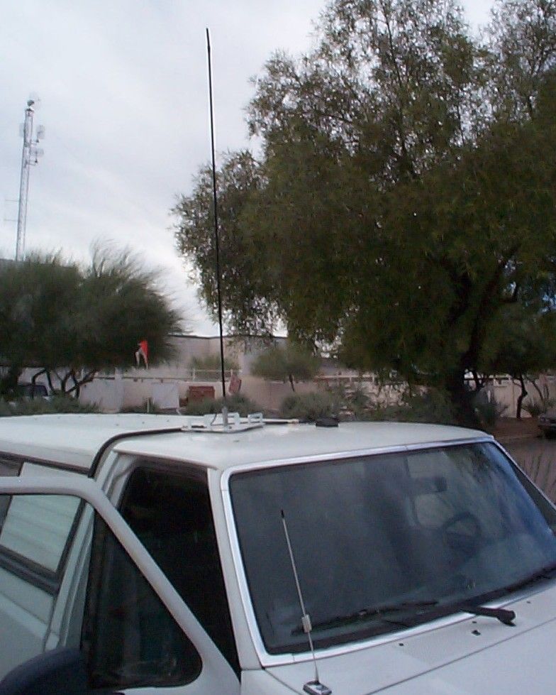
Chapter 2 — Hardware Installation 2-15 Revision A: October 2002 Figure 2.14RF Antenna Location You can also permanently mount the RF antenna by removing the magnets and bolting the antenna to the roof.
Users Manual
2-22Foreman PC Hardware Installation Guide Revision A: October 2002 Figure 2.21Power Cable 302203 Connected to Electrical Box Connecting the Attenuator (105919) 1Connect the attenuator (part number 105919) to the electrical box, as shown below. Figure 2.22Installed Attenuator Power cable 302203 Attenuator
Users Manual
Chapter 2 — Hardware Installation 2-23 Revision A: October 2002 Once the attenuator is installed, you must connect cable 302202 (drawing 403516) to the attenuator and to the top of the PC to connect the antenna to the built-in 2.4 GHz Cisco radio. Cable 302202 is terminated at one end, as shown below. Minimize cable 302202 for maximum power (six foot minimum for FCC compliance). Figure 2.23Terminated End of Cable 302202 2Terminate the other end of cable 302202, as shown in drawing 403516. 3Attach the terminated end to the attenuator and attach the other end to the top of the PC. Make sure the bend radius is 3 - 4 inches. Figure 2.24Cable 302202 Attached to Attenuator
Users Manual
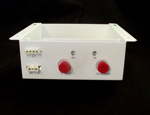
2-24Foreman PC Hardware Installation Guide Revision A: October 2002 Figure 2.25Cable 302202 Attached to Top of PC Connecting the RF Feedline (302255) to Electrical Box Terminate the RF feedline (part number 302255) (drawing 4013416) and connect it to the electrical box, as shown below. For maximum output power, minimize the length of this cable. The cable must be at least six feet long, however, for FCC compliance. Figure 2.26RF Feedline Connected RF feedline
Users Manual
Foreman PC Hardware Installation Guide Revision A: October 2002 Part Number 201265 RESTRICTIVE COVENANT AND DISCLAIMER Copyright © 2002 by Modular Mining Systems, Inc. Tucson, Arizona, U.S.A. All rights reserved. Modular Mining Systems, Inc., makes no representation regarding the fitness, quality, design, condition, capacity, suitability, or performance of the equipment or of the material or workmanship thereof and/or compliance of the system with the requirements of any law or regulations, and disclaims all warranties, either express or implied, including but not limited to any implied warranty of merchantability or fitness for any particular purpose. Modular Mining Systems, Inc., shall not be responsible for any loss or damage to property or injury or death to persons caused by any defect or failure in the system hardware and/or software regardless of the form of action, whether in contract or in tort, including negligence, strict liability, or otherwise. Modular Mining Systems, Inc., is not responsible for any losses, financial or otherwise, that the customer, purchaser, or end user (hereafter, collectively, user) incurs nor shall it be liable for any damages whatsoever (including, without limitation, damages for loss of business or investment profits, business interruption, loss of business information or the like) arising out of the use, interruption in the use of, or performance of the system hardware and/or software. User expressly agrees to indemnify and hold harmless Modular Mining Systems, Inc., from and against all claims, damages, losses, and expenses, including but not limited to: (i) any loss resulting from general or particular requirements of needs of user as defined in user’s originating purchase order; (ii) any damages from loss of use, loss of data, loss of profits, or loss of business arising out of or in connection with the performance of system hardware and/or software; (iii) any loss or damage to property or injury or death to persons proximately resulting from system hardware and/or software, even if entirely due in whole or in part to negligent acts or omissions of Modular Mining Systems, Inc.; and (iv) attorney’s fees and costs. The information described in this document is furnished as proprietary information and may not be copied or sold without the written permission of Modular Mining Systems, Inc. Trademarks The Modular distinctive font, MasterLink, ProVision, and WebReports are trademarks of Modular Mining Systems, Inc. The Modular logo, DISPATCH, and IntelliMine are registered U.S. trademarks of Modular Mining Systems, Inc. All other brand names and product names used in this book are trademarks, registered trademarks, or trade names of their respective holders. MANDATORY SAFETY INSTRUCTIONS TO INSTALLERS AND USERS Use only antennas supplied by Modular Mining Systems or dealer. Antenna Minimum Safe Distance: 20 cm Antenna Gain: Zero dBd referenced to a dipole. The Federal Communications Commission has adopted a safety standard for human exposure to RF (Radio Frequency) energy which is below the OSHA (Occupational Safety and Health Act) limits. Antenna Mounting: The antenna supplied by Modular Mining Systems or dealer must not be mounted at a location such that during radio transmission, any person or persons can come closer than the above minimum safe distance to the antenna, i.e. 20cm. To comply with current FCC RF exposure limits, the antenna must be installed at or exceeding the minimum safe distance shown above, and in accordance with the requirements of the Modular Mining Systems. 1. Mag Mount Roof-top Installation: The Mag mounted antenna assembly should be placed on the roof of the automobile. The 5 foot extension rod should not be modified. 2. Permanent Roof-top Installation: The magnetic base may be removed from the antenna assembly, however, the base of the assembly should be mounted to the top of the automobile so that the antenna is at least 4 feet over the roof. The 5 foot extension rod should not be modified. Antenna substitution: Do not substitute any antenna for the one supplied or recommended by Modular Mining Systems. You may be exposing person or persons to harmful radio frequency radiation. You may contact Modular Mining Systems for further instructions. WARNING: Maintain a separation distance from the antenna to person(s) of at least 20cm. You, as the qualified end-user of this radio device must control the exposure conditions of bystanders to ensure the minimum separation distance (above) is maintained between the antenna and nearby persons for satisfying RF Exposure compliance. The operation of this transmitter must satisfy the requirements of Occupational / Controlled Exposure Environment, for work-related use. Transmit only when person(s) are a least the minimum distance from the properly installed, externally mounted antenna. Contents iii Revision A: October 2002 About This Manual . . . . . . . . . . . . . . . . . . . . . . .v Audience. . . . . . . . . . . . . . . . . . . . . . . . . . . . . . . . . . . . . . . . . . . . . . v Chapter Table . . . . . . . . . . . . . . . . . . . . . . . . . . . . . . . . . . . . . . . . . v 1 Introduction . . . . . . . . . . . . . . . . . . . . . . . . . . . 1-1 What is the Foreman PC? . . . . . . . . . . . . . . . . . . . . . . . . . . . . . . 1-3 2 Hardware Installation . . . . . . . . . . . . . . . . . . 2-1 Tools Required . . . . . . . . . . . . . . . . . . . . . . . . . . . . . . . . . . . . . . . 2-3 Overview . . . . . . . . . . . . . . . . . . . . . . . . . . . . . . . . . . . . . . . . . . . 2-3 Installing the PC . . . . . . . . . . . . . . . . . . . . . . . . . . . . . . . . . . . . . 2-5 Installing the PC Pedestal . . . . . . . . . . . . . . . . . . . . . . . . . . 2-5 Using a Transmission Hump Assembly . . . . . . . . . . . . . 2-6 Using Floor Mount Bracket. . . . . . . . . . . . . . . . . . . . . . . 2-8 Installing the PC Mount and PC . . . . . . . . . . . . . . . . . . . . 2-11 Mountin…
Text truncated - open the document above for the full version.
ID Label/Location Info
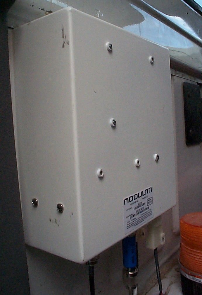
This device complies with Part 15 of the FCC Rules. Operation is subject to the following two conditions: (1) this device may not cause harmful interference, and (2) this device must accept any interference received, including interference that may cause undesired operation. Part Number: 302230 SERIAL NUMBER: XXXXXXXXXXXX TUCSON, ARIZONA MADE IN U.S.A. FCC ID: FJ6-302230 CANADA: XXXX YYYY ZZZZ
Operational Description
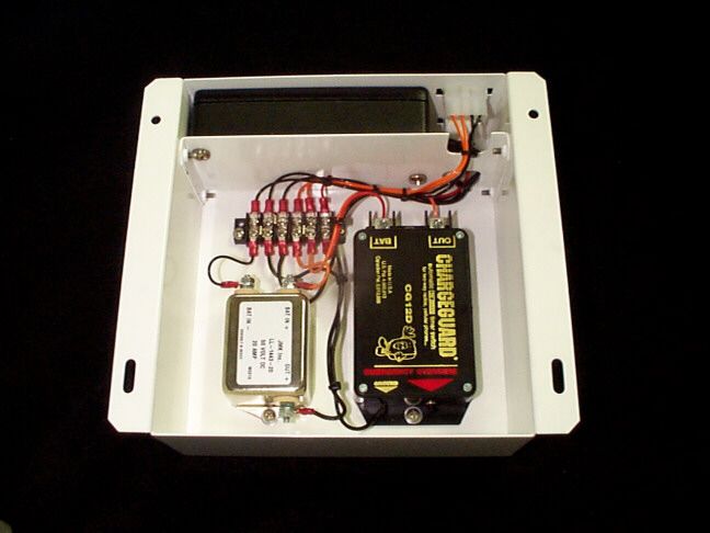
302230 System Theory Of Operation & Block Diagram By: Romer Johnson Date: 11-18-02 -------------------------------------------------------------------------------------------------------- Purpose: Using a unique Intra AP (Access point) routing scheme, Modular Mining is able to provide complete coverage of a mine site with an 802.11 wireless network. While the heavy equipment and AP’s are custom designed based on proprietary hardware and software, several customers have also asked for a standard ruggedized Windows based PC in order run some of their own applications. Description: In order to provide a solution to the customers, a foreman’s truck system has been designed using mostly off-the-shelf components. The ruggedized PC from TNAC contains a standard Cisco AIR LMC352 PCMCIA 802.11b wireless Card. Due to the significant losses of LMR-195 Cable, and the routing distances required in some pickups, a ½ Watt 2.4GHz RF bi-directional Amplifier was selected in order to counter these losses. This way, around ¼ Watt may be delivered to the 2.5dBi omni antenna. The Omni has been extended 5 feet above the roof of the automobile by using a fiberglass tube that has LMR-195 cable running down the center. This 5-foot extension is needed in a mine in order for the pickup to have LOS (Line-of-sight) RF coverage over the top of the high berms that line the haul roads. Mines are required to build high berms next to the haul roads in order to minimize the likelihood of a mine vehicle driving off the edge and falling into the pit. The extra gain from the RF amplifier is needed not only to counter the cabling losses inside the truck, but to provide the little extra range required to reach all of the scattered AP’s located throughout the mine property. Without the Amp and with 26 Feet of LMR-195 cabling losses there would only be 15.2dBm at the antenna, which would only provide for roughly 1 mile of coverage (Versus 3-4 miles with the amp). RF Operation Theory. The RF Block Diagram (302230) attached, illustrates all of the expected power levels and losses in the system. The TX path originates with the Cisco PCMCIA card which measured at exactly 100mW (20dBm) using an Agilent E4416A power meter (matches the datasheet perfectly). Six feet of LMR-195 Cable yields 1.1dB of loss at 2.4GHz. Combined with a 10dB pad at the input of the RF Amplifier, results in an input power of 8.9dBm (7.8mW) to the amp. This input power level was determined via testing in the lab to be optimal. At 8.9dBm the output power level is only 0.8dB less than the ½ Watt maximum and the output compression level is less than 0.1dB. This means that there is almost no rise in the side-bands due to the RF amplifier and the output power from the amp is 26.2dBm (417mW). Unfortunately, 20 more feet of LMR-195 cable is typically needed to route to the roof and up the 5-foot extension tube to reach the antenna. This results in an additional loss of 3.7dB, which means that at the antenna there is only 22.5dBm (178mW) of power remaining. If the amplifier enclosure is placed up high against the rear of the cab or just under the roof, the final cable run may be reduced to 10 feet. This would reduce cabling losses to 1.86dB resulting in 24.34dBm (272mW) at the antenna. Using the 2.5dBi omni antenna results in an estimated range of 3 miles (for 178mW) or 4 miles (for 272mW). Power Protection. The only other items in the 302230 enclosure are two power protection devices. The 20 Amp Automotive DC Filter and the 12V “ChargeGuard” help eliminate transient surges that could cause the ruggedized PC to reset. The ChargeGuard also incorporates over/under voltage protection and a power down timer. The power down timer is set to 15 minutes and will automatically power down the system after the vehicle has been turned off in order to prevent accidental discharging of the vehicles battery. Tuning / Calibration No tuning or calibration is required for this system. In fact, all of the Cisco radios that have been purchased for prototyping have been already calibrated to exactly 100mW. The RF amps are also within a very tight tolerance. The numbers discussed in the RF sections above should be accurate to within a dB for each installation.
Operational Description
Cisco Systems Copyright © 2001 Cisco Systems, Inc. All Rights Reserved. Page 1 of 6 Wireless client adapters are the key to adding mobility and flexibility to an enterprise—increasing productivity by enabling users to have network and Internet access anywhere within a building without the limitation of wires. The Cisco Aironet ® 350 Series Client Adapters are a complement to Aironet 350 Series infrastructure devices, providing an enterprise-ready solution that combines mobility with the performance, security, and manageability that people have come to expect from Cisco. Wireless client adapters connect a variety of devices to a wireless network either in ad hoc peer-to-peer mode or in infrastructure mode with APs. Available in PC Card (PCMCIA) and Peripheral Component Interconnect (PCI) form factors, Cisco Aironet 350 Series Client Adapters quickly connect desktop and mobile computing devices wirelessly to all network resources. With this product, you can instantly add new employees to the network, support temporary workgroups, or enable Internet access in conference rooms or other meeting spaces (see Figure 1). Features include: • Superior range and throughput • Secure network communications • World mode for international roaming • Full-featured utilities for easy configuration and management • Compliance with the IEEE 802.11b high-rate standard • Support for all popular operating systems DATASHEET CiscoAironet 350Series Client Adapters Cisco Systems Copyright © 2001 Cisco Systems, Inc. All Rights Reserved. Page 2 of 6 Figure 1Client devices equipped with wireless client adapters can roam freely throughout a facility via communications with multiple APs. Laptop with PC Card Adapter Roaming Access Point Tablet with PC Card Adapter Desktop with PCI Adapter Access Point Handheld with PC Card Adapter Switch with Inline Power (Cisco Catalyst 3524 PWR-XL) Router Laptop with PC Card Adapter LAN/WAN Ethernet Speed and Improved Range With a full 100 milliwatts (mW) of transmit power and the best receive sensitivity in the industry, the Cisco Aironet 350 Series Client Adapters provide the longest range and best reliability available for wireless clients. Advanced signal processing in the Cisco Aironet 350 Series helps manage the multipath propagation often found in office environments. Intelligent filtering addresses ambient noise and interference that can decrease network performance. Building upon Cisco leadership in wireless LAN (WLAN) performance, the Cisco Aironet 350 Series Client Adapters provide the greatest throughput available so users can enjoy virtually the same connectivity they gain from wire-line connections. Based on direct sequence spread spectrum (DSSS) technology and operating in the 2.4-GHz band, the Cisco Aironet 350 Series Client Adapters comply with the IEEE 802.11b standard—ensuring interoperability with all other compliant WLAN products. Industry-Leading Centralized Security Solution for the Enterprise For installations that need to scale to hundreds or even thousands of users, all Cisco Aironet products feature an industry-leading centralized security architecture based on the IEEE 802.1x standard (see Figure 2). Central to this architecture is the Extensible Authentication Protocol (EAP), that enables wireless client adapter manufacturers and Remote Access Dial-In User Service (RADIUS) server vendors to independently develop interoperable client- and server-side security software. This new security architecture provides centralized user-based authentication integrated with network logon via utilization of an EAP-enabled RADIUS server such as the Cisco Secure Access Control Server 2000 Version 2.6. When the user supplies a username and password, the client interacts with the RADIUS server through a Cisco Aironet AP. When the RADIUS server authenticates the client, the server and client negotiate a single-session, single-user encryption key and the RADIUS server transmits the key to the AP. With this centralized and standards-based architecture, wireless security scales to meet the requirements of any organization. Cisco Aironet 350 Series Client Adapters support the standard wired equivalent privacy (WEP) security architecture, and include 128-bit encryption key. Cisco Systems Copyright © 2001 Cisco Systems, Inc. All Rights Reserved. Page 3 of 6 Figure 2The 802.1x architecture implemented by Cisco is the first enterprise-ready security system for WLANs. EAP Over Wireless/LAN (EAPOW/EAPOL)EAP Over RADIUS Authenticator (Access Point, Catalyst Switch) Authentication Server such as ACS2000 v2.6 Semi-Public Network/Enterprise Edge Enterprise Intranet Extended Enterprise (Branch Office or Home Office) Supplicant R A D I U S World Mode for International Roaming Cisco simplifies deployment for international travelers and multinational corporations with a new client adapter setting called world mode. When placed in this mode, client adapters automatically inherit channel configuration properties directly from the Cisco Aironet AP to which they associate. This feature enables a user to use a client adapter around the world while still maintaining regulatory compliance. Enhanced Client Network Management Features with Extended Client Support All Cisco wireless client adapters include the Cisco Aironet Client Utility (ACU), a tool with an intuitive graphical user interface that makes it easy to configure, monitor, and manage an adapter (see Figure 3). The ACU includes site-survey tools that produce easy-to-understand, detailed graphical information, including signal strength, to assist in the correct placement of APs. The ACU now provides improved, quantifiable data, including signal-to-noise ratio measured in decibels (dB) and signal level and noise level measured in decibels per milliwatt (dBm). Using the ACU, a user can create a profile of settings for each environment, such as the office or home, making it simple for telecommuters and business travelers to reconfigure the adapte…
Text truncated - open the document above for the full version.
Operational Description
9309 Cincinnati-Columbus Rd. Suite#4 West Chester, Ohio 45069 PH: 513/779-2064 FAX: 513/779-2632 Http://www.rflinx.com Dec 28, 2001 ANTENNAFIER 2400 L SERIES TM The Antennafier TM 2400 LX and LE series are AGC compensated for constant Power Output Bi-directional Amplification. This provides con- stant maximum output power at the antenna over a wide RF input range. An antenna ampli- fier significantly improves the link reliability and operating range by Low Noise Amplification in Receive Mode, and Spectrally Clean Power Am- plification in Transmit Mode. This amplifier has unique internal 3-Pole filtering and AGC in both the TX and RX paths. This combination pro- vides exceptional cosite performance in high traffic areas. This amplification device is an RF subassembly. Its use in an RF sys- tem is subject to FCC approval. Featured Highlights: • High Dynamic Range • 3 Poles of High Q filtering in both TX/RX paths • Extremely low transmit harmonics • Transmit AGC (Automatic Gain Control) • Low Receive Noise Figure • Internal Lightning Protection • RX High Level AGC (preserves Noise Figure while providing maximum input dynamic range even with high inband RF levels. • TX/RX LED Indicator • Automatically switches between TX/RX • Rugged Weatherproof Housing LNA (AGC) RF IN/OUT RF OUT/IN DC FEED (OUTDOOR) LAN CARD/ RADIO 3 Pole BPF Coupler Coupler PA (AGC) ANTENNAFIER TM 2400 L SERIES BLOCK DIAGRAM DC FEED: INDOOR - Via. Connector on Antennafier OUTDOOR - DC sent through RF Coax 9309 Cincinnati-Columbus Rd. Suite#4 West Chester, Ohio 45069 PH: 513/779-2064 FAX: 513/779-2632 Http://www.rflinx.com Dec 28, 2001 ANTENNAFIER 2400 L SERIES TM Typical Performance Parameters Frequency Coverage: 2.44 GHz +/- 50MHz Supply Voltage: +12 to 15VDC Indoor Unit Connector 2.1mm I.D. (+), 5.5mm O.D. (-) Receive: Gain: 20 dB +/- 2 dB (Pin < -12dBm) High Level AGC Gain: Maintains Rcv Chain linearity when Rcv Pin > -12dBm by automatically reducing gain. High Level Rcv Gain = 4 dB +/- 2 dB Noise Figure: 5 dB Supply Current: < 200mA TX to RX Switching: 2 μSec IP 3 (Input): +13dBm Transmit: AGC Gain : Automatically adjusts to specified Power Output Loop 3dB Bandwidth = 150 KHz RF Input Pwr for Turn-On: > +2dBm to +20 dBm Harmonic Rejection: > 70dBc @ Power Out Supply Current: < 900mA RX to TX Switching: 2 μSec Maximum Ratings: Pin (Radio Port) +30 dBm Pin (Antenna Port) +27 dBm System Filtering: An internal 3-Pole Filter in both RX and TX Paths provides superior cosite performance achieving Maximum Dynamic Range and Low Harmonic Distortion. Size / RF Conn: 2.53” x 5.90”x 1.45” ( “N” type Female Connectors ) Weight: < 15 oz Chassis: Watertight Diecast Aluminum with tough black powder paint. Internal PCB is sealed via conformal coating to enhance weather protection. Indicator LED: Green LED -Receive Mode, Red LED-Transmit Mode Lightning Suppression: 1/4 wavelength short 9309 Cincinnati-Columbus Rd. Suite#4 West Chester, Ohio 45069 PH: 513/779-2064 FAX: 513/779-2632 Http://www.rflinx.com Dec 28, 2001 ANTENNAFIER 2400 L SERIES TM Series - Power Description 2400 LX 2 W (+33dBm) 1 W (+30dBm) 0.5 W (+27dBm) 0.25 W (+24dBm) 0.10 W (+20dBm) Outdoor Rated Amplifier with mounting bracket and stainless steel hardware included. The Kit version includes a 2.4 GHz DC FEED and 15VDC Wall Mount Power Supply. 2400 LE 2 W (+33dBm) 1 W (+30dBm) 0.5 W (+27dBm) 0.25 W (+24dBm) 0.10 W (+20dBm) Indoor Rated Amplifier, with 15VDC Wall Mount Power Supply, mounting bracket and stainless steel hardware included 2400 LU Up to 2 Watts Custom "Built to Order", Specify RX Gain, TX Gain. Indoor or Outdoor model available. Kit includes 15VDC Wall Transformer, stainless steel hardware and 2.4 GHz DC FEED & mount- ing bracket where applicable. ANTENNAFIER TM Ordering Guide
Parts List/Tune Up Info
RF LINX: 9309 Cincinnati-Columbus Rd. Suite #4 West Chester, OH. 45069 PH: 513-779-2064 FAX: 513-779-2632 www.rflinx.com GHARGEGUARD, Inc 400 Highland Ave Altoona, PA. 16602 PH: 800-458-3410 FAX: 814-942-7064 www.chargeguard.com System Tuning / Calibration No tuning or calibration is required for this system. In fact, all of the Cisco radios that have been purchased for prototyping have been already calibrated to exactly 100mW. The RF amps are also within a very tight tolerance. The numbers discussed in the RF sections of the “RF System Theory” paper should be accurate to within a dB for each installation.
Parts List/Tune Up Info
302230 System Active Components and Tuning By: Romer Johnson Date: 11-18-02 -------------------------------------------------------------------------------------------------------- Active Components: Since the 302230 is built using off-the-shelf components, all active components are at the product level. These are as follows: ITEM Part # Manufacturer Description 1. Aironet LMC352 CISCO 100mW Wireless 802.11b 2.4GHz Radio PCMCIA Card 2. DP-860-DB9 TIP Ruggedized Keyboard 3. TNA1201 TNAC Ruggedized Computer 4. 2400LE-500mW-MM part of the Antennafier 2400L Series RF LINX Bi-directional Amp 2.4GHz ½ Watt 5. GG12D Charge Guard 12V System Protector with over/under cut-out and timer Manufacturer Information: CISCO Systems Inc. 320 Springside Dr. Akron, OH. 44333 PH: 330-664-7900 FAX: 330-664-7922 www.cisco.com TNAC: (Technic N. America Corp) now named JLT Mobile Computers Inc. 5505 W. Chandler Blvd. Chandler, AZ. 85226 PH: 480-705-4200 FAX: 480-705-4216 www.jltmobilecomputers.com www.tnacorp.com TIP (Texas Industrial Peripherals) P.O. Box 49182 Austin, TX. 78765 PH: 800-866-6506 FAX: 512-837-0207 www.ikey.com RF LINX: 9309 Cincinnati-Columbus Rd. Suite #4 West Chester, OH. 45069 PH: 513-779-2064 FAX: 513-779-2632 www.rflinx.com GHARGEGUARD, Inc 400 Highland Ave Altoona, PA. 16602 PH: 800-458-3410 FAX: 814-942-7064 www.char…
Text truncated - open the document above for the full version.
Contact Information
Applicant
Les Zoschke(Vice President, Product Development)
Technical Contact
M. Flom Associates, IncMorton Flom
[email protected]480 926 3100
3356 N. San Marcos Pl., Suite 107 · Chandler, Arizona · United States
Non-Technical Contact
M. Flom Associates, Inc.Morton Flom
[email protected]480 926 3100
Test Firm
M. Flom Associates, Inc.Morton Flom
Technical Specifications
| # | Rule Parts | Frequency Range | Power Output |
|---|---|---|---|
| 1 | 15C | 2.41 GHz - 2.46 GHz | 100.00 mW |
Other Applications from Modular Mining Systems Inc

FJ6-302395
Feb 23, 2004802.11b UNIT
Equipment Class
DTS - Digital Transmission System
FJ6-301582
Jul 04, 2001Spread Spectrum Transceiver
Equipment Class
DSS - Part 15 Spread Spectrum TransmitterFJ6VECTORPP12
Oct 30, 1991Radio Modem/Data Concentrator This device must be supplied with an interface cable which incorporates a ferrite core equivalent to the type used during Certification testing.
Equipment Class
JBP - Part 15 Class B Computing Device PeripheralFJ6VECTORPP96
Oct 30, 1991Radio Modem/Data Concentrator This device must be supplied with an interface cable which incorporates a ferrite core equal to the type used during Certification testing.
Equipment Class
JBP - Part 15 Class B Computing Device PeripheralFJ646H8102SP
Jan 15, 1987DXX - Part 15 Low Power Communication Device Transmitter
Equipment Class
DXX - Part 15 Low Power Communication Device Transmitter