FL924000Radar Intrusion Detection Link, model 24000
Perimeter Products Inc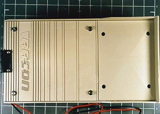
Click to zoom
Application Details
- Equipment Class
- FDS - Part 15 Field Disturbance Sensor
- Date of Grant
- Mar 28, 2001
- Application Purpose
- Original Equipment
- Date of Application
- Nov 29, 2000
- Equipment Note
- Radar Intrusion Detection Link, model 24000
- Frequency Range
- 24100.00000000 - 24100.00000000
- Company
- Perimeter Products Inc
- Country
- United States
Documents & Files
Document Text
Text extracted from the exhibit documents filed with the FCC. Open a document above to read the original.
Users Manual
i TABLE OF CONTENTS INTRODUCTION4 GENERAL SPECIFICATIONS4 SITE PREPARATION6 INSTALLATION7 OFFSETS10 INSTALLATION – MECHANICAL11 INSTALLATION – ELECTRICAL12 TRANSMITTER WIRING12 OPERATING INSTRUCTIONS15 ELECTRICAL ALIGNMENT19 SENSITIVITY ADJUSTMENT20 THEORY OF OPERATION21 TROUBLESHOOTING24 TEST POINTS24 ii F IGURE 1: M ODEL 24000 .................................................................................................... 4 F IGURE 2: S YSTEM C O MPONENTS ....................................................................................... 6 F IGURE 3: R EQUIRED C LEARANCE A REA ............................................................................ 8 F IGURE 4: T ERRAIN ............................................................................................................. 8 F IGURE 5: P HYSICAL P ROTECTION ...................................................................................... 9 F IGURE 6: P ERIMETER L AYOUT ........................................................................................ 10 F IGURE 7: O FFSET I LLUSTRATION ..................................................................................... 10 F IGURE 8: O FFSET A RRANGEMENTS : T YPICAL H IGH S ECURIT Y I NSTALLATION ................ 11 F IGURE 9: P OST I NSTALLATION AND M OUNTING U NITS . E RROR ! B OOKMARK NOT DEFINED . F IGURE 10: M OUNTING H EIGHT C HART ......................... E RROR ! B OOKMARK NOT DEFINED . F IGURE 11: T RANS MITTER W IRING ................................................................................... 14 F IGURE 12: R ECEIVER W IRING .......................................................................................... 17 F IGURE 13: A NTENNA C ONFIGURATIONS .......................................................................... 19 F IGURE 14: T RANS MITTER B LOCK D IAGRAM .................................................................... 22 F IGURE 15: R ECEIVER B LOCK D IAGRAM .......................................................................... 23 F IGURE 16: T RANS MITTER C IRCUIT B OARD C O MPONENT L OCATION ............................... 26 F IGURE 17: R ECEIVER C IRCUIT B OARD C OMPONENT L OCATION ...................................... 27 iii 4 Introduction The Perimeter Products, inc. Model 24000 Bi-Static Microwave Link consists of a microwave transmitter and a receiver unit. Each system is designed to detect motion in a specified area called a detection zone. This detection zone is established by the transmitter, which sends continuous microwave signals to the receiver. Any motion in the detection zone causes a variation in the received signal strength. These signal variations are detected by the receiver and processed to give an intrusion notification. Each transmitter and receiver is mounted in a weatherproof enclosure. Each enclosure contains the respective electronic circuitry, and may be wired to report attempts of tampering. An antenna is part of each electronic enclosure. The antenna on the transmitter contains the microwave source. The receiver antenna contains the microwave detector. This Installation and Operations Manual is intended for the person who will be doing the initial site layout and installation of the PPi Microwave Intrusion Detection System., Model 24000. It provides the information required to install your system from the time of unpacking shipped equipment to verification of an operative system after installation. This manual covers site preparation, installation procedures, operating instructions and general theory of operation Figure 1: Model 24000 GENERAL SPECIFICATIONS Circuit Components100% solid state 5 Power Requirements11 to 15 VDC Can be provided by PPi Uninterruptible Power Supply UPS-PFI Power Consumption100 MA total per system maximum Transmitter70 MA Receiver30 MA Microwave Carrier Frq.24.125 GHz +/- 50 MHz Operating Range800 ft., 243 meters Antenna PatternShort Range 24° Medium Range 16° Long Range 11° Antenna PolarizationE-Plane Vertical (E-Plane Horizontal Optional) Operating Temperature -40°F to +158°F (-40°C to + 70°C) Dimensions6” W X 3.5” D X 12.5 “ H 16 cm W X 9 cm D X 32cm H Weight5 lbs., 2.25kg Shipping Weight8 lbs., 3.5kg Transmitter Unit Tamper Circuit Contact1A, 28 VDC ModulationType: square wave type A2 Channels: 6 field selectable Microwave OutputLess than .25 volts/meter, maximum at 98 Ft. (30 meters) Remote TestingBuilt-in self-test generator simulates acutual intrusion signals Receiver Unit DemodulationCorrelated balanced demodulator Alarm Relay2A at 28 VDC 6 Alarm DurationAdjustable .5 sec. To 10 sec. Figure 2: System Components SITE PREPARATION Site preparation is necessary for satisfactory performance of the Model 24000 unit. The amount and type of site preparation required depends on the level of security desired. The physical specifications for a high security detection zone are: • Transmitter/receiver separation distance no longer than 328 ft. (100 meters) • Terrain must be level to grade, +/- 3 in. (7.6cm) 7 • Terrain void of vegetation • Transmitter/receiver units mounted 24 in. (60cm) beam centerline (center of antenna) to ground When physical properties of the detection zone are not within these parameters, the system capabilities are diminished. High security applications require much more stringent specifications than do applications where only a beam-break alarm is required. The following parameters should be used to determine the level of security required. High Security Zone – Detection of intruder stomach-crawling parallel to the beam Medium Security Zone – Detection of intruder crawling on hands and knees. Low Security Zone – Beam-break alarm only – detection of a walking intruder, vehicles, etc. (not recommended) INSTALLATION Installation should begin with a survey of the area to be covered to ensure that it meets the site requirements. After the location of Transmitters and Receivers has been determined, poles should be set and conduit terminated. Th…
Text truncated - open the document above for the full version.
Operational Description
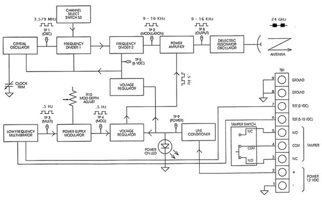
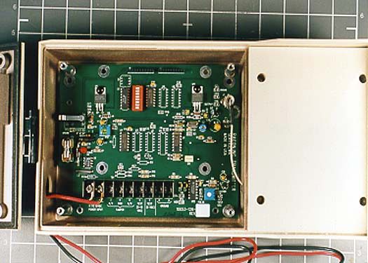
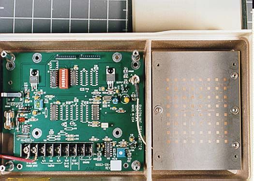
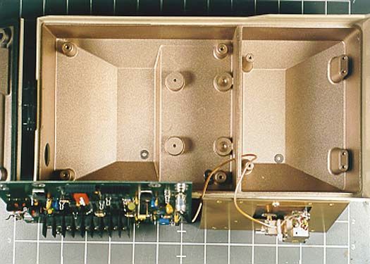
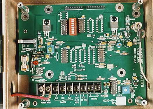
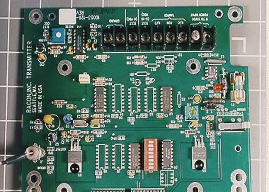
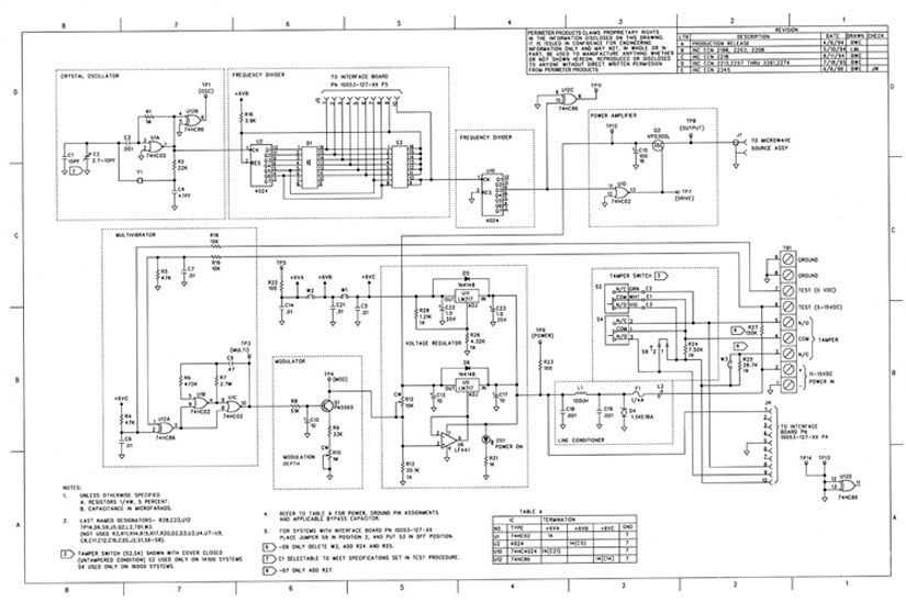
PERIMETER PRODUCTS 43180 Osgood Road, Fremont, CA 94539 Tel: 510-249-1450 Fax: 510-249-1540 EXPOSITORY STATEMENT FOR MODEL 24000 TRANSMITTER General Description: The Perimeter Products Inc., Model 24000 Transmitter is the transmitter portion of a bi-static radar intrusion detection link (field disturbance sensor). The transmitter source operates with 1.6 mW output power in the 24075 to 24175 MHz band and is modulated at a 50% duty cycle at any one of six user- selectable frequencies ranging from about 9.5KHz to 16KHz. The printed circuit board, microwave source, and planar array antenna are installed in a common shielded plastic housing. The unit operates from a nominal 12VDC power source. Operating principle: The transmitter aims a narrow beam of RF at the receiver. Anything intruding into the beam varies the amplitude of the received signal. This amplitude variation is filtered and compared to the normal signal, causing an alarm condition. Circuit Description: A fixed reference frequency of 3.579MHz is provided by a crystal. The specific modulating frequency (channel) is selected by configuring a "divide by" counter using a set of switches in accordance with the installation manual. The 24GHz microwave source is powered through an FET which is switched by the modulating signal. Antenna: The antenna is a 64 element planar array directly attached to the source assembly. The circuit board and source/antenna assembly are connected by an internally mounted coaxial cable Attachments: A circuit diagram is shown at figure 1. A block diagram with signal path and frequencies is at figure 2. Figure 1: Circuit Diagram Figure 2: Block Diagram
Test Report
Page 1 of 25 Report No: FC00-035 CERTIFICATION TEST REPORT FOR THE RADAR INTRUSION DETECTION LINK, 24000 TRANSMITTER FCC PART 15 SUBPART C 15.245 COMPLIANCE DATE OF ISSUE: APRIL 21, 2000 PREPARED FOR: Perimeter Products, Inc. 12628 Interurban Avenue South Seattle, WA 98168 P.O. No: 12062 W.O. No: 73440 PREPARED BY: Joyce Walker CKC Laboratories, Inc. 5473A Clouds Rest Mariposa, CA 95338 Date of test: February 29 - March 10, 2000 Report No: FC00-035 DOCUMENTATION CONTROL: _____________________________ Tracy Phillips Documentation Control Supervisor CKC Laboratories, Inc. APPROVED BY: _____________________________ Dennis Ward Director of Laboratories CKC Laboratories, Inc. This report contains a total of 25 pages and may be reproduced in full only. Partial reproduction may only be done with the written consent of CKC Laboratories, Inc. Page 2 of 25 Report No: FC00-035 TABLE OF CONTENTS Administrative Information ............................................................................................. 3 Summary Of Results........................................................................................................ 4 Equipment Under Test (EUT) Description...................................................................... 4 Measurement Uncertainty................................................................................................ 4 EUT Operating Frequency............................................................................................... 4 Peripheral Devices ........................................................................................................... 4 Report Of Measurements................................................................................................. 5 Table 1: Fundamental Emission Levels.............................................................. 5 Table 2: Six Highest Radiated Emission Levels - 9kHz-18GHz........................ 6 Table 3: Six Highest Radiated Emission Levels - 18-100GHz .......................... 7 Table A : List Of Test Equipment ................................................................................... 8 EUT Setup .......................................................................................................................9 Test Instrumentation And Analyzer Settings................................................................... 9 Table B : Analyzer Bandwidth Settings Per Frequency Range........................... 9 Spectrum Analyzer Detector Functions............................................................... 10 Peak ......................................................................................................... 10 Quasi-Peak............................................................................................... 10 Average.................................................................................................... 10 Test Methods ................................................................................................................... 11 Radiated Emissions Testing................................................................................. 11 Sample Calculations ........................................................................................................ 12 Appendix A : Information About The Equipment Under Test........................................ 13 I/O Ports............................................................................................................... 14 Crystal Oscillators ............................................................................................... 14 Printed Circuit Boards ......................................................................................... 14 Cable Information................................................................................................ 14 Required EUT Changes To Comply.................................................................... 14 Photograph Showing Radiated Emissions ........................................................... 15 Photograph Showing Radiated Emissions ........................................................... 16 Appendix B : Measurement Data Sheets ......................................................................... 17 Band Edges .......................................................................................................... 18 Page 3 of 25 Report No: FC00-035 CKC Laboratories, Inc. has Certificates of Accreditation from the following agencies: DATech (Germany); A2LA (USA); FCC (USA); VCCI (Japan); BSMI (Taiwan); HOKLAS (Hong Kong). CKC Laboratories, Inc. has Letters of Acceptance through an MRA for the following agencies: ACA/NATA (Australia); SABS (South Africa); SWEDAC (Sweden); TUV Rheinland-Germany; TUV Rheinland- Korea; TUV Rheinland-Russia; Radio Communications Agency (RA); NEMKO (Norway). ADMINISTRATIVE INFORMATION DATE OF TEST: February 29 - March 10, 2000 PURPOSE OF TEST: To demonstrate the compliance of the Radar Intrusion Detection Link, 24000 Transmitter, with the requirements for FCC Part 15 Subpart C 15.245 devices. MANUFACTURER: Perimeter Products, Inc. 12628 Interurban Avenue South Seattle, WA 98168 REPRESENTATIVE: John Kurmel TEST LOCATION: CKC Laboratories, Inc. 22105 Wilson River Hwy, Tillamook, OR 97141 5289 NE Elam Young Pkwy, Hillsboro, OR 97124 TEST PERSONNEL: Mike Wilkinson & Bill Baker TEST METHOD: ANSI C63.4 1992 FREQUENCY RANGE TESTED: 9 kHz - 100 GHz EQUIPMENT UNDER TEST: Radar Intrusion Detection Link Manuf:Perimeter Products, Inc. Model:24000 Transmitter Serial:5540-07 FCC ID:FL924000 (pending) Page 4 of 25 Report No: FC00-035 SUMMARY OF RESULTS The Perimeter Products, Inc. Radar Intrusion Detection Link, 24000 Transmitter, was tested in accordance with ANSI C63.4 1992 for compliance with FCC Part 15 Subpart C 15.245. As received, the above equipment was found to be fully compliant with the limits of FCC Part 15 Subpart C 15.245. The results in this report apply only to th…
Text truncated - open the document above for the full version.
Contact Information
Applicant
Robert C. Williams(Vice President, Engineering)
650 966-8550
Technical Contact
5473A Clouds RestTracy Phillips
[email protected]1-800-500-4362
5473A Clouds Rest · Mariposa, California · United States
Non-Technical Contact
5473A Clouds RestJoyce Walker
[email protected]1-800-500-4362
Test Firm
CKC Laboratories, Inc.Steve Behm
Technical Specifications
| # | Rule Parts | Frequency Range | Power Output |
|---|---|---|---|
| 1 | 15C | 24.10 GHz - 24.10 GHz | - |
Other Applications from Perimeter Products Inc
FL9MPS4100
Sep 02, 1996Security System Transmitter
Equipment Class
FDS - Part 15 Field Disturbance SensorFL98H94000
Jul 13, 1986FDS - Part 15 Field Disturbance Sensor
Equipment Class
FDS - Part 15 Field Disturbance Sensor