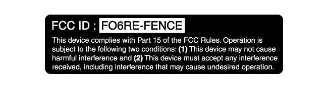
FO6RE-FENCEDogtra E-Fence System
Han Seung Enterprise Co Ltd
Click to zoom
Application Details
- Equipment Class
- DCD - Part 15 Low Power Transmitter Below 1705 kHz
- Date of Grant
- Mar 23, 2004
- Application Purpose
- Original Equipment
- Date of Application
- Mar 23, 2004
- Equipment Note
- Dogtra E-Fence System
- Frequency Range
- 0.01000000 - 0.01000000
- Company
- Han Seung Enterprise Co Ltd
- Country
- South Korea
Documents & Files
Document Text
Text extracted from the exhibit documents filed with the FCC. Open a document above to read the original.
Users Manual
OWNER’S MANUAL 2 CONTENTS 3 OVERVIEW Thank you for purchasing our dogtra e-Fence System. With dogtra e-Fence System your dog can freely play around within the boundaries you have selected. With the proper training you will enjoy seeing your dog in good demeanor. MAIN FEATURES • Collar/Receiver – Newly designed to make adjusting the collar strap easy. • Waterproof Housing – The collar/receiver is waterproof. • Wall transmitter features lightning/surge protection. • Dogtra e-Fence has a warning/vibration signal before electrical stimulation/correction is given to the dog. • A wire indicator shows the continuity of fencing wires. • Levels are easily adjusted using the intensity selection dial on the wall mount transmitter. • Dogtra e-Fence is easy to install and use. 4 SAFETY • Dogtra e-Fence collars use state-of-the-art microcomputer technology. The receiver has an automatic control which limits the stimulus to eight seconds. • Dogtra’s filtering system prevents reception from outside sources other than your transmitter. DOGTRA e-Fence System PACKAGE CONTENTS • Wall-Mount Transmitter • Collar/Receiver • Battery Charger and Adapter • Te s t L a m p • Flags (boundary training flags) • Underground Fence Wire (500 feet) • Splicer • Lightning/Surge Protective Wire • Accessory Magnet • Transmitter Mount Screws (2ea) • Owner’s Manual 5 DESCRIPTION OF TRANSMITTER PARTS dogtra e-Fence Transmitter Adaptor Jack Connector Wire Connectors ON/OFF & Function Selection Switch Field Width Adjustment Knob Intensity Selection Dial ON/OFF Indicator Light Wire Indicator Light 6 ON/OFF & Function Selection Switch The On/Off Selection switch has three functions. When the toggle switch is up, the warning/vibration followed by stimulation will occur. When this switch is down, only stimulation occurs. When the switch is in the middle, the power is Off. Pager/Stimulation OFF Stimulation 7 Field Width Adjustment Knob This knob controls the width of the signal field (the distance from the boundary wire to the location where the collar/receiver first activates). Turning the knob clockwise increases the field width, giving your dog wider buffer area before the activation. Turning it counterclockwise decreases the distance between the dog and fence before activation. Intensity Selection Dial The Intensity Selection Dial controls the stimulation level. Level 1 is the lowest setting and level 5 is the highest. It is always best to start at level 1 and increase the levels until you find a level where the dog reacts to the stimulation but does not overreact with excessive vocalization. 8 ON/OFF Indicator Light When the On/Off & Function Selection switch is either in the up or down position, the LED light will be on, indicating that the power is on. When the switch is in the middle position, the light goes off, indicating that the power is off. 9 Wire Indicator Light When the wires are connected properly, the wire indicator light will be on. In the event the e-Fence wire becomes damaged, the light will automatically turn off. 10 Wire Connectors The easy-to-use push-release wire connectors let you instantly connect or disconnect the boundary wire leads. Wires should be stripped about a half inch before being inserted into the red connectors on the bottom of the wall mount transmitter. Dogra e-Fence comes with lightning/surge protective wires. Insert the protective wires to the black connector on the bottom of the wall transmitter. Black Connector (for the protective wires) 11 Adaptor Jack Connector Plug the 110-volt adaptor into a 110-volt wall outlet and insert the adaptor plug into the adaptor jack connector of the transmitter. Adaptor Jack Connector 12 Wall-Mount Transmitter Use the (2) included screws to mount the transmitter to a wall securely, near any standard 110-volt household outlet. The unit will withstand freezing temperatures, but it is not waterproof. Therefore, we recommend mounting the transmitter in a safe, dry indoor area. To power the wall transmitter, plug the AC adaptor into the standard 110-volt outlet and connect it to the adaptor jack connector of the transmitter. 13 DESCRIPTION OF COLLAR PARTS dogtra e-Fence Receiver Collar strap Battery Charging Receptacle and Cover ON/OFF Magnetic Switch Indicator Light Contact Point 110-volt 14 ON/OFF Magnetic Switch To activate the Dogtra e-Fence, place the accessory magnetic switch (located on the top of the wall mount transmitter) to the red dot on the collar/receiver. Hold them together for a moment until the LED indicator light starts flashing on the receiver. The indicator light will blink once every two seconds showing that the unit is charged and ready to use. (If the red indicator light emits a double blink every two seconds, the batteries need to be charged.) To deactivate the Dogtra e-Fence, place the accessory magnetic switch (located on the top of the wall mount transmitter) to the red dot on the collar/receiver. The LED light will stop blinking indicating that the unit is now off. To attain maximum battery life, deactivate the unit when not in use. Accessory Magnetic Switch 15 Receiver Indicator Light (LED) Located on the front of the collar, the indicator light comes on and blinks once every two seconds after the collar is turned on. The blinking will change from a single flash to a double flash when the collar needs to be recharged. The indicator light will come on when the dog reaches the edge of the signal field in the yard. 16 Contact Points The collar should be fitted so that the stainless steel contact points press firmly against the dog’s skin. A loose fit can allow the collar to move around on the dog’s neck which may cause irritation to the skin. If the collar is too loose, electrical contact will be inconsistent and your corrections will be inconsistent as well. 17 Collar/Receiver Battery Charging Receptacle On the inside of the collar/receiver, next to the collar strap, is the battery charging receptacle with a rubber cover plug. 18 Battery…
Text truncated - open the document above for the full version.
External Photos
[External Photos]
Internal Photos
[Internal Photos]
Operational Description
A DESCRIPTION OF A CIRCUIT OPERATION TRANSMITTER 1. SW2 is a Power Switch and also a Mode select Switch. This switch has 3 functions according to the location of the switch lever. When the switch lever is in the middle, a transmitter is deactivated. And when the switch lever is upward or downward, the transmitter is activated. When the switch lever is upward (Mode 1), it causes pager and shock. And when the switch lever is downward (Mode 2), it causes shock. 2. D2 is a power indicator. 3. U2 is 5V Regulator IC. 4. SW1 is a Shock Level Switch of 5 levels. 5. U1 is a microprocessor for transmission. It receives the information about the mode from the mode select switch and outputs the signal corresponding to it from data line. When it outputs the information, it also outputs the information of Shock Level according to SW1. 6. D1 is a LED sensing broken fence wires. If fence wires are properly connected, the LED comes on and if fence wires are broken, it goes off. 7. Q1 and Q2 are TR for data amplification and output. 8. S1, S2, S3, F1 and F2 are the circuits protecting a transmitter from lightning strike. 9. U3 and P1 select a jumper according to the length of fence wire connected to P2. When 1Pin and 6Pin of P1 are connected and it is set at 2000feet, the length of fence wire is available by 2000feet. 10. VR1 controls the range from the fence wire to the operating receiver. 11. Jack1 is for AC ADAPTOR.
Test Report
KTL Korea Testing Laboratory Page 1 of 9 TEST REPORT This test report only responds to the tested sample and shall not be reproduced except in full without written approval of the Korea Testing Laboratory. Tested and reported by Reviewed by Jeong-Min Kim, Senior Engineer Hee-Soo Kim , Telecommunication Team Manager KOREA TESTING LABORATORY FG101-01-02-00 222-13, Guro-Dong Guro-Gu Seoul Korea 152-053 http://www.ktl.re.kr Ref. Report No. 04-1341-004 Name and address of the applicant Han Seung Enterprise Co., Ltd. 715-2, Gojan-dong, Namdong-ku, Incheon, 405-821 Korea Standard / Test regulation FCC Part 15, Subpart C Test result Pass Incoming date : January 30, 2004 Test item(s) ; Low Power Tx below 1.705MHz (Dog Fence) Model/type ref. ; DOGTRA e-Fence System Manufacturer ; Han Seung Enterprise Co., Ltd. Additional information ; -Required Authorization : Certification -FCC ID. : FO6RE-FENCE Test date : February 27, 2004 Issue date : March 8, 2004 Ref. Report No. 04 - 1341 – 004 Page 2 of 13 Korea Testing Laboratory Telecommunication Team 222-13, Guro3-dong, Guro-gu, Seoul Korea 152-848 TABLE OF CONTENTS I. GENERAL INFORMATION 3 1. Grantee’s Name and Mailing Address 2. Manufacturer's Name and Mailing Address 3. Equipment Descriptions 4. Rules and Regulations 5. Measuring Procedure 6. Place of Measurement 7. Date of Measurement . GENERAL REQUIREMENTS OF THE EUT 4 1. Labeling Requirement (Section 15.19) 2. Information to User (Sections 15.21) 3. Special Accessories (Section 15.27) . CONDUCTED EMISSION MEASUREMENT (Section 15.207) 5 1. Test Procedure 2. Photograph for the test configuration 3. Sample Calculation 4. Measurement Data . RADIATED EMISSION MEASUREMENT (Section 15.209) 9 1. Test Procedure 2. Photograph of the test configuration 3. Sample Calculation 4. Measurement Data . TEST EQUIPMENTS USED FOR MEASUREMENT 13 Ref. Report No. 04 - 1341 – 004 Page 3 of 13 Korea Testing Laboratory Telecommunication Team 222-13, Guro3-dong, Guro-gu, Seoul Korea 152-848 . GENERAL INFORMATION 1. Grantee’s Name and : Han Seung Enterprise Co., Ltd. Mailing Address 715-2, Gojan-dong, Namdong-ku, Incheon, 405-821 Korea 2. Manufacturer's Name and : Han Seung Enterprise Co., Ltd. Mailing Address 715-2, Gojan-dong, Namdong-ku, Incheon, 405-821 Korea 3. Equipment Descriptions 3.1 Operating Frequency : 10.0 kHz 3.2 Power Supply : DC 12 V (Adapter ) 3.3 Adapter used : Model: AEC-4112B, Manufacturer: ANOMA ELECTRIC CO., LTD. 4. Rules and Regulations : FCC Part 15, Subpart C 5. Measuring Procedure : ANSI C63.4-2001 6. Place of Measurement : Open Area Test Site (KTL) 7. Date of Measurement 7.1 Conducted Emission : February 27, 2004 7.2 Radiated Emission : February 27, 2004 Ref. Report No. 04 - 1341 – 004 Page 4 of 13 Korea Testing Laboratory Telecommunication Team 222-13, Guro3-dong, Guro-gu, Seoul Korea 152-848 . GENERAL REQUIREMENTS OF THE EUT 1. Labeling Requirement (Section 15.19) This device complies with Part 15 of the FCC Rules. Operation is subject to the following two conditions: (1) this device may not cause harmful interface, and (2) this device must accept any interference received, including interference that may cause undesired operation. 1.1 Location of Label : Rear side of EUT 1.2 How Applied : Printed on Adhesive Label 2. Information to User (Section 15.21) The following or similar statements were provided in the manual for user instruction. Please refer page 31 of the attached manual for details. CAUTION : Any changes or modifications in construction of this device which are not expressly approved by the party responsible for compliance could void the user's authority to operate the equipment. 3. Special Accessories (Section 15.27) 3.1 Were the special Accessories provided? [ ] yes, [ x ] no 3.2 If yes, details for the special accessories are as follows : 3.3 If yes, were the appropriate instructions provided on the first page of the text concerned with the installation of the device? [ ] yes, [ ] no 3.4 Are these accessories provided of the type which can be readily obtained from multiple retail outlets ? [ ] yes, [ ] no And therefore does the manual specify what additional components or accessories are required to used in order to comply with the Rules? [ ] yes, [ ] no Ref. Report No. 04 - 1341 – 004 Page 5 of 13 Korea Testing Laboratory Telecommunication Team 222-13, Guro3-dong, Guro-gu, Seoul Korea 152-848 . CONDUCTED EMISSION MEASUREMENT (Section 15.207) 1. Test Procedure Conducted emission measurements on the EUT were performed by "AC Power Line Conducted Emissions Testing" procedure as per ANSI C63.4. The EUT was set up on a wooden table 0.8 meters height, 1.0 by 1.5 meters in size, placed in the shielded enclosed with a side of wall of which constituted a vertical conducting surface of 2.2 m x 3.1 m in size to maintain 40 cm from the rear of EUT. LISN(Line Impedance Stabilization Network, EMCO, 3825/2, 50 ohm / 50 μH) was installed and electrically boned to the conducting ground plane. One of two 50 ohm output terminals of the LISN was connected to the EMI Test Receiver(R&S, ESI, 20 Hz to 7 GHz) and the other was terminated in 50 ohms. Measurements were again performed after interchanging such a connection oppositely. The frequency range from 150 kHz to 30 MHz was examined and the peak values that are within 6 dB of the limit would be compared to quasi-peak values using the Quasi-Peak Detector Function. The voltage developed across the 50 ohms port in LISN was measured and graphed by the EMI Test Receiver. The 6 dB bandwidth of the EMI Test Receiver was set to 9 kHz. The position of connecting cables of the EUT was changed to find the worst case configuration during measurements. The maximum emission level from the EUT occurred in such configuration as shown in the following photograph. Ref. Report No. 04 - 1341 – 004 Page 6 of 13 Korea Testing Laboratory Telecommunication Team 222-13, Guro3-dong, Guro-gu, Seoul Korea 152-848 2. Photograph for the test configuration 3. Sample Calculati…
Text truncated - open the document above for the full version.
Test Setup Photos
Ref. Report No. 04 - 1341 – 004 Page 6 of 13 Korea Testing Laboratory Telecommunication Team 222-13, Guro3-dong, Guro-gu, Seoul Korea 152-848 2. Photograph for the test configuration 3. Sample Calculation The emission level measured in decibels above one microvolt (dB?) was converted into microvolt (?) as shown in following sample calculation. For example : Measured Value at 4.645 MHz 47.2 dB? @ Q-peak mode + Cable Loss* 0.0 dB = Conducted Emission 47.2 dB? * In case of RG214/ RF cable 15 Ft, the loss is about 0.17 dB at the frequency of 30 MHz which is negligible. Ref. Report No. 04 - 1341 – 004 Page 10 of 13 Korea Testing Laboratory Telecommunication Team 222-13, Guro3-dong, Guro-gu, Seoul Korea 152-848 2. Photograph of the test configuration 3. Sample Calculation The emission level measured in decibels above one microvolt (dB?) was calculated as shown in following sample calculation. For example : Measured Value at 0.010 MHz 63.8 dB? + Antenna Factor 19.0 dB/m + Cable Loss 0.0 dB - Preamplifier 0.0 dB - Distance Correction Factor * 59.1 dB = Radiated Emission 23.7 dB?/m * Extrapolated from the measured distance to the specified distance by an inverse linear distance extrapolation.
Contact Information
Applicant
Ho-Yun So(President)
Test Firm
Korea Testing LaboratoryJeong-Min Kim
Technical Specifications
| # | Rule Parts | Frequency Range | Power Output |
|---|---|---|---|
| 1 | 15C | 0.01 MHz - 0.01 MHz | - |
Other Applications from Han Seung Enterprise Co Ltd
FO6R400DT
Sep 12, 1995Dog Collar Receiver
Equipment Class
CRR - Superregenerative ReceiverFO6S400DT
Sep 12, 1995Transmitter for Dog Training Collar
Equipment Class
DSC - Part 15 Security/Remote Control TransmitterFO6RD300DT
Jun 25, 1991Dog Collar Receiver
Equipment Class
CYY - Communications Receiver used w/Pt 15 Transmitter