FRW2000-800800 MHz TRANSCEIVER
Wulfsberg Electronics Division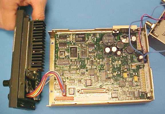
Click to zoom
Application Details
- Equipment Class
- TNB - Licensed Non-Broadcast Station Transmitter
- Date of Grant
- Oct 23, 2003
- Application Purpose
- Original Equipment
- Date of Application
- Oct 23, 2003
- Equipment Note
- 800 MHz TRANSCEIVER
- Frequency Range
- 806.00000000 - 870.00000000
- Country
- United States
Documents & Files
Document Text
Text extracted from the exhibit documents filed with the FCC. Open a document above to read the original.
Users Manual
Operator’s Manual P-2000 and C-2000/RT-2000 Transceiver Systems P-2000 Part Number: 400-049200-11-xxx-xxxx-xxxx Software Mod: 1 C-2000 Part Number 400-049300-11-xxx-xxxx-xxxx Software Mod: 1 RT-2000 Part Number 400-049400-11-xxx-xxxx-xxxx Software Mod: 1 Wulfsberg ElectronicsP-2000 and C-2000/RT-2000 Operator’s Manual Document 150-041102 Revision APage 2 of 37 TABLE OF CONTENTS INTRODUCTION .......................................................................................................................................................3 F EATURES..................................................................................................................................................................3 T RANSCEIVER OVERVIEW..........................................................................................................................................4 BASIC OPERATIONS................................................................................................................................................5 F RONT PANEL & CONTROLS.......................................................................................................................................5 K EYPAD BUTTONS......................................................................................................................................................6 T HE HOME PAGE........................................................................................................................................................7 S ETTING THE DISPLAY BRIGHTNESS.........................................................................................................................10 S ETTING THE VOLUME LEVEL..................................................................................................................................10 S ELECTING THE ACTIVE TRANSCEIVER....................................................................................................................11 S ELECTING A STANDBY CHANNEL USING THE CURSOR/TUNE KNOB.......................................................................12 S ELECTING A CHANNEL USING THE KEYPAD...........................................................................................................12 S ELECTING A CHANNEL BY ALPHANUMERIC IDENTIFIER.........................................................................................13 U SING THE DIRECT/REPEAT FEATURE......................................................................................................................13 R ECEIVING/TRANSMITTING......................................................................................................................................14 E NABLING/DISABLING TRANSCEIVERS.....................................................................................................................14 QMEM OPERATIONS ............................................................................................................................................15 MESSAGE PAGE......................................................................................................................................................16 PROGRAMMING/EDITING A PRESET CHANNEL .........................................................................................18 E DITING A PRESET CHANNEL...................................................................................................................................19 C HANGING TRANSMIT POWER..................................................................................................................................19 ENHANCED SYSTEM FEATURES.......................................................................................................................20 R ELAY MODE...........................................................................................................................................................20 S IMULCAST MODE....................................................................................................................................................21 R ELAY/SIMULCAST MODE.......................................................................................................................................22 R EPEATER MODE......................................................................................................................................................23 XTS-E MULATION MODE..........................................................................................................................................24 P HONE PATCH MODE...............................................................................................................................................24 ENCRYPTION FEATURES ....................................................................................................................................25 T URNING ENCRYPTION ON AND OFF........................................................................................................................25 S ELECTING AN ENCRYPTION KEY.............................................................................................................................25 P ERFORMING AN OTAR ...........................................................................................................................................26 L OADING ENCRYPTION KEYS...................................................................................................................................28 E RASING ENCRYPTION KEYS WITH A KEYLOADER.................................................................................................29 CPS MODE ................................................................................................................................................................30 L OADING CHANNEL MEMORY..................................................................................................…
Text truncated - open the document above for the full version.
Users Manual
Publication No. 150-049105 Page 1 of 39 Rev. A P-2000 Operator’s Manual Oct 2003 Operator’s Manual P-2000 and C-2000/RT-2000 Transceiver Systems P-2000 Part Number: 400-049200-11-xxx-xxxx-xxxx Software Version: 1 C-2000 Part Number 400-049300-11-xxx Software Version: 1 RT-2000 Part Number 400-049400-11-xxx-xxxx-xxxx Software Version: 1 P-2000/C-2000/RT-2000 Operator’s Manual Page 2 of 39 Publication No. 150-049105 P-2000 Operators Manual Rev. A Oct 2003 TABLE OF CONTENTS INTRODUCTION .......................................................................................................................................................3 F EATURES..................................................................................................................................................................4 T RANSCEIVER OVERVIEW..........................................................................................................................................5 BASIC OPERATIONS................................................................................................................................................6 F RONT PANEL & CONTROLS.......................................................................................................................................6 K EYPAD BUTTONS......................................................................................................................................................7 T HE HOME PAGE........................................................................................................................................................8 S ETTING THE DISPLAY BRIGHTNESS.........................................................................................................................11 S ETTING THE VOLUME LEVEL..................................................................................................................................11 S ELECTING THE ACTIVE TRANSCEIVER....................................................................................................................12 S ELECTING A STANDBY CHANNEL USING THE CURSOR/VALUE KNOB.....................................................................13 S ELECTING A CHANNEL USING THE KEYPAD...........................................................................................................13 S ELECTING A CHANNEL BY ALPHANUMERIC IDENTIFIER.........................................................................................14 U SING THE DIRECT/REPEAT FEATURE......................................................................................................................14 R ECEIVING/TRANSMITTING......................................................................................................................................15 E NABLING/DISABLING TRANSCEIVERS.....................................................................................................................15 QMEM OPERATIONS ............................................................................................................................................16 MESSAGE PAGE......................................................................................................................................................17 PROGRAMMING/EDITING A PRESET CHANNEL .........................................................................................19 E DITING A PRESET CHANNEL...................................................................................................................................20 C HANGING TRANSMIT POWER..................................................................................................................................20 ENHANCED SYSTEM FEATURES.......................................................................................................................21 R ELAY MODE...........................................................................................................................................................21 S IMULCAST MODE....................................................................................................................................................22 R ELAY/SIMULCAST MODE.......................................................................................................................................23 R EPEATER MODE......................................................................................................................................................24 XTS-E MULATION MODE..........................................................................................................................................25 P HONE PATCH MODE...............................................................................................................................................25 ENCRYPTION FEATURES ....................................................................................................................................26 T URNING ENCRYPTION ON AND OFF........................................................................................................................26 S ELECTING AN ENCRYPTION KEY.............................................................................................................................26 P ERFORMING AN OTAR ...........................................................................................................................................27 L OADING ENCRYPTION KEYS...................................................................................................................................29 E RASING ENCRYPTION KEYS WITH A KEYLOADER.................................................................................................30 CPS MODE ................................................................................................................................................................31 L OADING CHANNEL MEMORY....…
Text truncated - open the document above for the full version.
Users Manual
Installation Manual P-2000 and C-2000/RT-2000 Transceiver Systems P-2000 Part Number: 400-049200-11-xxx-xxxx-xxxx Hardware Mod: 1 C-2000 Part Number 400-049300-11-xxx-xxxx-xxxx Hardware Mod: 1 RT-2000 Part Number 400-049400-11-xxx-xxxx-xxxx Hardware Mod: 1 P-2000/C-2000/RT-2000 Installation Manual Page 2 of 41 Publication No. 150-049106 P-2000 Installation Manual Rev. A Oct 2003 RF Exposure Information This radio is restricted to occupational/controlled applications where users have been made aware of the potential for exposure and can exercise control over their exposure. Antennas used for the radio must not exceed the antenna gain shown below for each transmit frequency range. The antenna must be installed at least or exceeding the minimum distance away from any person(s) depending on the transmit frequency. Frequency Max Antenna Gain Min Distance 136 – 174 MHz 0 dBi 21 cm (8.3 in) 403 - 470 MHz 3 dBi 25 cm (9.9 in) 450 – 520 MHz 3 dBi 25 cm (9.9 in) 806 – 870 MHz 3 dBi 21 cm (8.3 in) Transmit no more than 50 % of the time. Measurable RF energy exposure occurs only when transmitting. Failure to observe these restrictions will result in exceeding the FCC RF exposure limits. P-2000/C-2000/RT-2000 INSTALLATION MANUAL Publication No. 150-049106 Page 3 of 41 Rev. A P-2000 Installation Manual Oct 2003 SECTION 1 – GENERAL INFORMATION 1. Introduction This section contains information relative to the physical, mechanical, and electrical characteristics of the Wulfsberg Electronics “2000” Family of Communications Systems. 2. Applicability This manual applies only to the P-2000 panel mount transceiver, C-2000 control unit, and RT- 2000 remote mount transceiver. 3. Equipment Description The Wulfsberg “2000” family FM Communications System is a dual transceiver FM voice communications link between the aircraft and ground facilities. The system has not been designed by the manufacturer to be installed on Type Certificated aircraft. Installations on these type of aircraft are subject to applicable FAA regulations. The “2000” family consists of the P-2000 panel mount transceiver and C-2000/RT-2000 control and remote mount transceiver. A. P-2000 Panel Mount FM Communications Transceiver The Wulfsberg P-2000 is a FM Tactical transceiver that incorporates one or two transceiver modules and control functions into a single panel mount unit. Part number variations of the unit exist for any combination of the following frequency bands: 138-174 MHz, 403-470 MHz, 450-520 MHz, and 806-870 MHz. Each transceiver module with the exception of the 806-870 MHz band can transmit with 1 or 10 Watts transmit power. The 800 MHz unit produces 1 and 3 watts transmit power. The P-2000 can operate by itself or in conjunction with the C-2000 control display acting as a remote slave control. Input voltage is 28 volts DC and the keypad is backlit from either 28VDC, 5 VDC or 5 VRMS AC. The P-2000 transceiver is designed to be mounted in the instrument panel that will fit a standard DZUS mounting. Two connectors, a DB-25 and DB-15 accept all harness wiring on the rear of the P-2000, while two TNC type RF connector provides the antenna connection through conventional coaxial cables. For models containing one transceiver, only one antenna port is provided. The P-2000 consists of functional subassemblies interconnected via standard connectors and ribbon cables. The case of the P-2000 is designed to be disassembled easily to expose most subassemblies or circuit modules for service. All adjustments to audio levels can be made via software and do not require the disassembly of the box. Internal test points are exposed and available to the service technician without having to remove circuit module subassemblies or use extender cables or cards. The P-2000 is designed to be drop-in replacement for the C-962A/S Control unit for the Wulfsberg RT-9600/7200 transceiver systems also known as the ARC-513 with the exception of the 28 Volt input power. Due to increased 28 power requirements of the P-2000, wire size P-2000/C-2000/RT-2000 Installation Manual Page 4 of 41 Publication No. 150-049106 P-2000 Installation Manual Rev. A Oct 2003 on this input may need to be increased to 20 AWG. All other microphone inputs/headset outputs and backliting are compatible. B. C-2000 Control Display Unit The Wulfsberg C-2000 is a control display unit that can be used as a slave control head with a P-2000 panel mount transceiver, or as a primary or slave control head for the RT- 2000 remote transceiver. Versions of the C-2000 include black faceplate and options for either Standard or NVG compatible displays. Input voltage is 28 volts DC and the keypad is backlit from either 28 VDC, 5 VDC or 5 VRMS. The C-2000 Control Display Unit is designed to be mounted in the instrument panel that will fit a standard DZUS mounting. Two connectors, a DB-25 and DB-15, accept all harness wiring on the rear of the P-2000. Front panel controls establish and display the operating status of all RT-2000 or P-2000 functions when operating as a slave control unit. C. RT-2000 Remote Mount FM Communications Transceiver The Wulfsberg RT-2000 is a FM Tactical transceiver that incorporates one or two transceiver modules and control functions into a single panel mount unit. Part number variations of the unit exist for any combination of the following frequency bands: 138-174 MHz, 403-470 MHz, 450-520 MHz, and 806-870 MHz. Each transceiver module with the exception of the 806-870 MHz band can transmit with 1 or 10 Watts transmit power. The 800 MHz unit produces 1 and 3 watts transmit power. The RT-2000 is designed to be controlled by a C-2000 control display. Input voltage is 28 volts DC and the keypad is backlit from either 28VDC, 5 VDC or 5 VRMS AC. The RT-2000 transceiver is designed to be mounted rack mounted. Two connectors, a DB- 25 and DB-15 accept all harness wiring on the rear of the RT-2000, while two TNC type RF connector provides the antenna connection through conventional coaxia…
Text truncated - open the document above for the full version.
Attestation Statements
_____________________________________________________________________________________ 6400 Wilkinson Drive Prescott, AZ 86301-6164 USA Phone 1-928-708-1550 Fax 1-928-541-7627 www.Wulfsberg.com Wulfsberg Electronics A Chelton Group Company September 17, 2003 Authorization & Evaluation Division Federal Communications Commission Laboratory 7435 Oakland Mills Road Columbia, MD 21046 Ladies and Gentlemen, Reference: Application for Certification of Transceiver with FCC ID: FRW2000-800 This equipment meets the requirements of 47 CFR 90.203(e). Programming of this product’s transmit frequencies can be performed only by the manufacturer, or by service or maintenance personnel. The operator cannot program transmit frequencies using the equipment’s external operation controls. Please contact me at 928-708-1543 if you require any additional information. Regards, /S/ Mary Beaumont Mary Beaumont Principal RF Engineer Email: [email protected]
Cover Letter(s)
_____________________________________________________________________________________ September 12, 2003 Authorization & Evaluation Division Federal Communications Commission Laboratory 7435 Oakland Mills Road Columbia, MD 21046 Subject: Confidentiality Request - Application for Certification of Transceiver with FCC ID: FRW2000-800 Ladies and Gentlemen: Wulfsberg Electronics is requesting that the Exhibits listed below be withheld from public view per the provisions of CFR 47 Part 0.459. Wulfsberg Electronics considers the information in these exhibits to be classified as trade secrets, pursuant to 47 CFR Part 0.457 (d). Release of such information could result in serious harm and the loss of company proprietary information. Exhibit 4P-2000 Circuit Descriptions Exhibit 5 Schematic Diagrams Exhibit10Part Lists Exhibit 12Operational Description Please contact me if you require any additional information. Regards, /S/ Mary Beaumont Mary Beaumont Principal RF Engineer 928-708-1543 Email: [email protected] Wulfsberg Electronics A Chelton Group Company 6400 Wilkinson Drive Prescott, AZ 86301-6164 USA Phone 1-928-708-1550 Fax 1-928-541-7627 www.Wulfsberg.com
Cover Letter(s)
October 20, 2003 Applicant: Wulfsberg Electronics Division Equipment: FCC ID: FRW2000-800 Reference: Job #1388UC3 Please note that the FCC ID has only one set of ‘FRW’ (on all the correspondence from Timco, the Grantee code has been repeated) 1) Attached please find Tune-up Procedures, Circuit Descriptions of the ITM, Schematics and BOM of the transmitter boards. 2) Attached please find new Internal Photos. 3) Please find amended MPE page attached. 4) Attached please find MPE label. 5) The 100 cm separation distance was incorrectly given. It should have been 30 cm as shown on page 6 of the Environmental Assessment report. The 100 cm was the effect of various configurations shown on pages 8, 10 and 12. Please find corrected ‘ Mandatory Safety Instructions to Installers and Users’ which will appear in the manual. 6) Please see corrected pages 12 and 13.
External Photos
Internal Photos Of Complete Assembly All versions of the P-2000/C-2000/RT-2000 Use the same internal connections and shielding as shown below: Unit Completely Assembled - Top View Unit Opened Showing Connection between Power Supply and CPU Board Ribbon Cable. Also Blue RF cables run from ITM module to Power Amp Modules. Step 3: Remove Front Panel/Display Assembly to show Front Loading Connector and CPU Board Connection Via Cable Assembly. View of ITM modules located below the CPU board. The Black and Red wires provide 8VDC power to the ITM Modules. Step 4: Slide CPU Board Out To Reveal ITM Modules inside. Interconnect is accomplished with Flex-cables. One for each ITM Module. View of Flex-cables and Power cables from each ITM to the CPU Board Step 5: CPU board completely removed. One ITM and Cover has been removed from chassis. Step 6: ITM Cover removed reveals the ITM module inside with ribbon cable and blue RF cable. Step 7: ITM Module without Cover View of ITM end of the Flex-cable. View of Power cables on underside of ITM Step 8: System with covers removed from Power Amplifier Modules. Step 9: Both ITM Modules with covers removed
External Photos
External Pictures Front View Rear View Right Side View Left Side View
ID Label/Location Info
APPLICATION REVISIONS RE V FINAL ASSEMBLY REV DESCRIPTION DATE APPROVED APPROVED A INITIAL RELEASE PER DCN W2424 SH 1 DWG. NO. 156-049087 THIS DOCUMENT CONTAINS PROPRIETARY INFORMATION OF WULFSBERG ELECTRONICS DIVISION, A CHELTON GROUP COMPANY, NEITHER RECEIPT NOR POSSESSION THEREOF CONFERS ANY RIGHT TO REPRODUCE OR USE, OR DISCLOSE, IN WHOLE OR IN PART, ANY SUCH INFORMATION WITHOUT WRITTEN AUTHORIZATION FROM WULFSBERG ELECTRONICS DIVISION APPROVALS DATE DRAWN CHECKED LABEL, FCC ID, P-2000 and RT-2000 ENGINEER SIZE A CAGE CODE 1B7G3 DWG NO. 156-049087 REV A ISSUED SCALE: NONE DO NOT SCALE DRAWING SHEET 1 OF 2 NOTES: 1. MATERIAL: 156-040975 DIE CUT SPECIFICATION FOR CLUSTER 1 TAMPER PROOF PERMANENT LABELS OR 156-040963 STANDARD CUT TAMPER PROOF PERMANENT LABEL 2. LETTERS: BLACK THERMAL TRANSFER 3. BACKGROUND: SILVER (MATTE FINISH) 4. BORDER: BLACK NONE CUT-LINE 5. CORNER: ROUNDED SQUARE 6. ARTWORK: USE DATAFILE LABEL IMAGE 156-049087.X.LBL (X = CURRENT REV OF THIS DOCUMENT) 7. THERMAL RIBBON: RHD TT BLK 80MM X 300M REVERSE 8. FILL IN FIELDS (eg. UNIT DASH NUMBERS, SERIAL NUMBERS) TO BE MARKED PER 150-341005 “WORK INSTRUCTIONS FOR THERMAL LABELS” TAG NO. SIZE -01 .70” X 1.80” -02 .70” X 1.80” -03 .70” X 1.80” -04 .70” X 1.80” REV A SH 2 DWG. NO. 156-049087 SIZE A CAGE CODE 1B7G3 DWG. NO. 156-049087 REV A PROPRIETARY NOTICE ON TITLE PAGE APPLIES SCALE: NONE DO NOT SCALE DRAWING SHEET 2 OF 2 DIMENSIONS: UNITS: INCHES TOLERANCES: .XX+/-.03 -04 Compliance Label RF Exposure Warning Label Label size is 1.06 x 1.56 with no border. FCC/Canada Label Location Information (Top View Of Unit) Integrated Transceiver Module #2 FCC Label Integrated Transceiver Module #1 FCC Label FM #2 RF Output Connector FM #1 RF Output Connector Part Number Label Hardware Mod Status Industry Canada Label Software Mod Status Label FCC Part 15 Compliance Label (located on the bottom) Industry Canada Label RF Exposure Warning Label
Internal Photos
Internal Photos CPU Board - Top View CPU Board - Bottom View Power Supply Board - Top View Power Supply Board - Bottom View VHF Power Amp - Top View VHF Power Amp Board - Bottom View UHF Power Amp - Top View UHF Power Amp - Bottom View 800 MHz Power Amp - Top View 800 MHz Power Amp - Bottom View Display Board - Top View Display Board - Bottom View Switch Board - Top View Switch Board - Bottom View VHF Integrated Transceiver Module - Top View VHF Integrated Transceiver Module - Bottom View VHF Integrated Transceiver Module: FCC ID- AZ489FT3790 UHF-1 Integrated Transceiver Module - Top View UHF-1 Integrated Transceiver Module - Bottom View UHF-1 Integrated Transceiver Module: FCC ID- AZ489FT4822 UHF-2 Integrated Transceiver Module - Top View UHF-2 Integrated Transceiver Module - Bottom View UHF-2 Integrated Transceiver Module: FCC ID- AZ489FT4821 800 MHz Integrated Transceiver Module - Top View 800 MHz Integrated Transceiver Module - Bottom View 800 MHz Integrated Transceiver Module – FCC ID- AZ489FT5774
Internal Photos
800 MHz Integrated Transceiver Module - Top View 800 MHz Integrated Transceiver Module - Bottom View 800 MHz Integrated Transceiver Module – FCC ID- AZ489FT5774 800 Controller Board - Top View 800 Controller Board - Bottom View 800 RF Board with Shields - Top View 800 RF Board without Shields - Top View 800 RF Board with Shields - Bottom View 800 RF Board without Shields - Bottom View 800 Vocoder Board - Top View 800 Vocoder Board - Bottom View
Parts List/Tune Up Info
Wulfsberg Electronics FCC IDS: FRW2000-VHF A Chelton Group CompanyFRW2000-UHF1 FRW2000-UHF2 FRW2000-800 10.1 (1/1) 10.1 Tune-up Procedure Factory alignment of the P-2000 and RT-2000 circuits require the use of equipment and proprietary test fixtures that are highly specialized and difficult to reproduce. The P-2000 and RT-2000 require factory alignment. Hence, the alignment procedures will not be offered in this report. Both the output power level and frequency of the Internal Transceiver Modules (ITMs) may be fine adjusted by the customer, using appropriate test equipment and Motorola proprietary Customer Programming Software (CPS). This software must be purchased from Motorola and comes with an instruction guide on the CD-ROM.
Parts List/Tune Up Info
650-049200 REV. A Page 1 of 7 APPLICATION REVISIONS REV A NEXT ASSEMBLY FINAL ASSEMBLY REV DESCRIPTION DATE APPROVED APPROVED A --- SH 1 DWG. NO. 650-049200 THIS DOCUMENT CONTAINS PROPRIETARY INFORMATION OF WULFSBERG ELECTRONICS DIVISION, A CHELTON GROUP COMPANY, NEITHER RECEIPT NOR POSSESSION THEREOF CONFERS ANY RIGHT TO REPRODUCE OR USE, OR DISCLOSE, IN WHOLE OR IN PART, ANY SUCH INFORMATION WITHOUT WRITTEN AUTHORIZATION FROM WULFSBERG ELECTRONICS DIVISION APPROVALS DATE DRAWN S HOVELSRUD 8/1/03 CHECKED --- --- TEST PROCEDURE P-2000/C-2000/RT-2000 SYSTEM ENGINEER S HOVELSRUD 8/1/03 SIZE A CAGE CODE 1B7G3 DWG NO. 650-049200 REV A ISSUED --- --- SCALE: NONE DO NOT SCALE DRAWING 650-049200 REV. A Page 2 of 7 1.0 PURPOSE This document describes the performance tests required for a P-2000/C-2000/RT-2000 after it has been assembled from tested modules. The test procedure is divided into seven categories: 1. Software Loading/Audio and Transmitter Alignment. 2. Pre-environmental Test. 3. Environmental Test Cold. 4. Environmental Test Hot. 5. Burn-in 6. Vibration Test. 7. Final Test. 2.0 SCOPE All part numbers of the Flexcomm 2000 Family can be tested with this procedure. The table below lists the specific sections of this test procedure that must be used for testing a P-2000, C-2000, and RT-2000 respectively. 3.0 Certification of Board and Modules Certification of boards/modules is accomplished by installing the board/module into a test P- 2000/C-2000/RT-2000. The board/module is a “certified part” when the complete unit passes all tests as listed in this test procedure. Section P-2000 C-2000 RT-2000 6. Setup 6.1 (Software Loading) Yes Yes Yes 6.2 (Transmitter Setup) 6.2.1 (VHF 136-174) (Attachment A) 400-049200-XX-XXX- X1XX-X1XX No 400-049400-XX-XXX- X1XX-X1XX 6.2.2 (UHF 403-470) (Attachment B) 400-049200-XX-XXX- X2XX-X2XX No 400-049400-XX-XXX- X2XX-X2XX 6.2.3 (UHF 450-520) (Attachment C) 400-049200-XX-XXX- X3XX-X3XX No 400-049400-XX-XXX- X3XX-X3XX 6.2.4 (800 MHz) (Attachment D) 400-049200-XX-XXX- X4XX-X4XX No 400-049400-XX-XXX- X4XX-X4XX 6.3 (Audio Setup) Yes No Yes 650-049200 REV. A Page 3 of 7 4.0 Required Equipment AC Voltmeter Fluke Model 77 or Equivalent. Environmental Chamber capable of +60°C. to -30°C. Vibration Table. TSH-2000 Interface box. Power Supply 18-33 volts DC, 5 amp with voltage and CURRENT meters. RF Cables and power cables. Communication analyzer Motorola model R-2670. 650-049200 REV. A Page 4 of 7 5.0 SYSTEM INTERCONNECT AND TURN ON PROCEDURE 1) Connect the TSH-2000 25 Pin Connector to the P-2000 UUT. 2) Connect the Power Supply to the TSH-2000. 3) Connect the Test C-2000 to the TSH-2000. 4) Connect the RF output connector of the P-2000 under test to the R-2670 as required. 5) Connect the Audio input/output ports of the TSH-2000 to the R-2670 as required per the test procedure. Figure 1 P-2000/C-2000/RT-2000 SYSTEM TEST INTERCONNECT Computer RF Input/Output Audio Input/Output R-2670 Communication Analyzer (COMAN) TSH-2000 UUT P-2000 Or C-2000 Or RT-2000 Power Supply 18-33 Volts (5 Amps) C-2000 Test Controller 650-049200 REV. A Page 5 of 7 6.0 P-2000/C-2000/RT-2000 SETUP PROCEDURES Perform the following tests for each unit marking all test data sheets as required: 6.1 Software Loading Connect the test system as outline in section 5. Turn power on and verify unit turns on and that current draw is < 1 amp. 6.1.1 P-2000 Using the procedure outlined in WED document 650-049200-01, load the current software revision into both the Display processor and the CPU board Processor. Mark software revision numbers on the appendix A data sheet. 6.1.1 C-2000 Using the procedure outlined …
Text truncated - open the document above for the full version.
Contact Information
Applicant
James F Buehring(Certification Manager)
Test Firm
M. Flom Associates, Inc.Morton Flom
Technical Specifications
| # | Rule Parts | Frequency Range | Power Output | Emission | Tolerance |
|---|---|---|---|---|---|
| 1 | 9 | 806 MHz - 870 MHz | 3 W | 20K0F1E | 1.5 ppm |
Other Applications from Wulfsberg Electronics Division
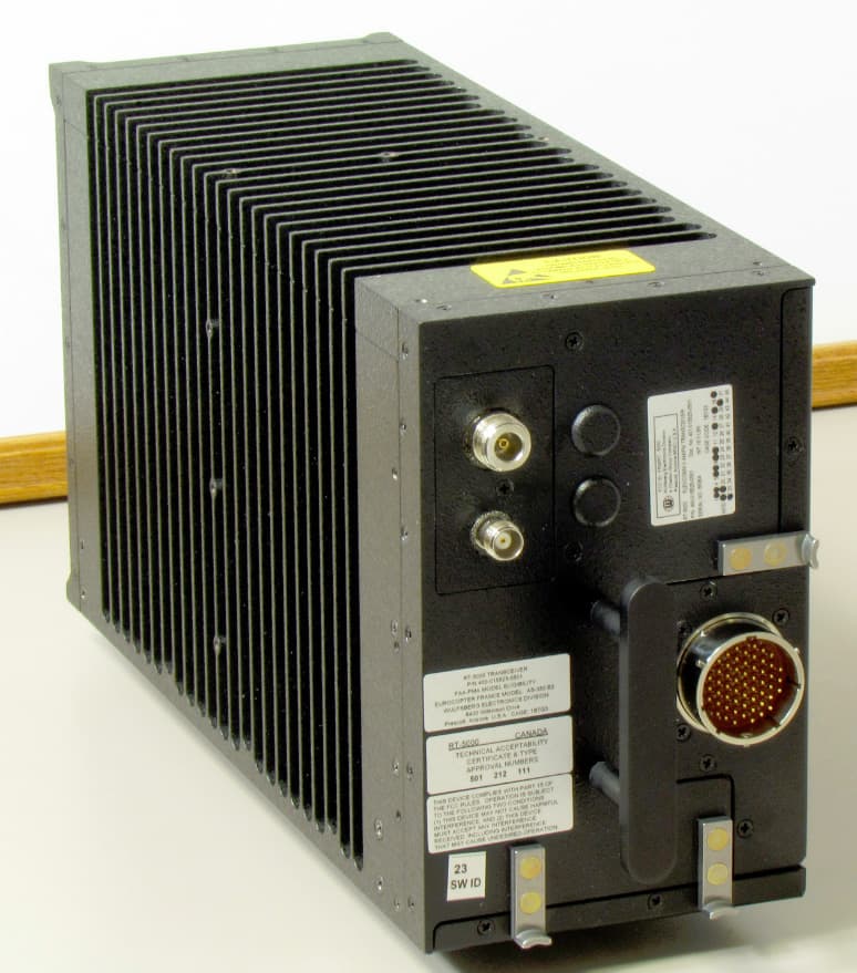
FRWRT-5000P-03
Dec 28, 201229.7 to 960 MHz Tactical Airborne Transceiver
Equipment Class
TNB - Licensed Non-Broadcast Station Transmitter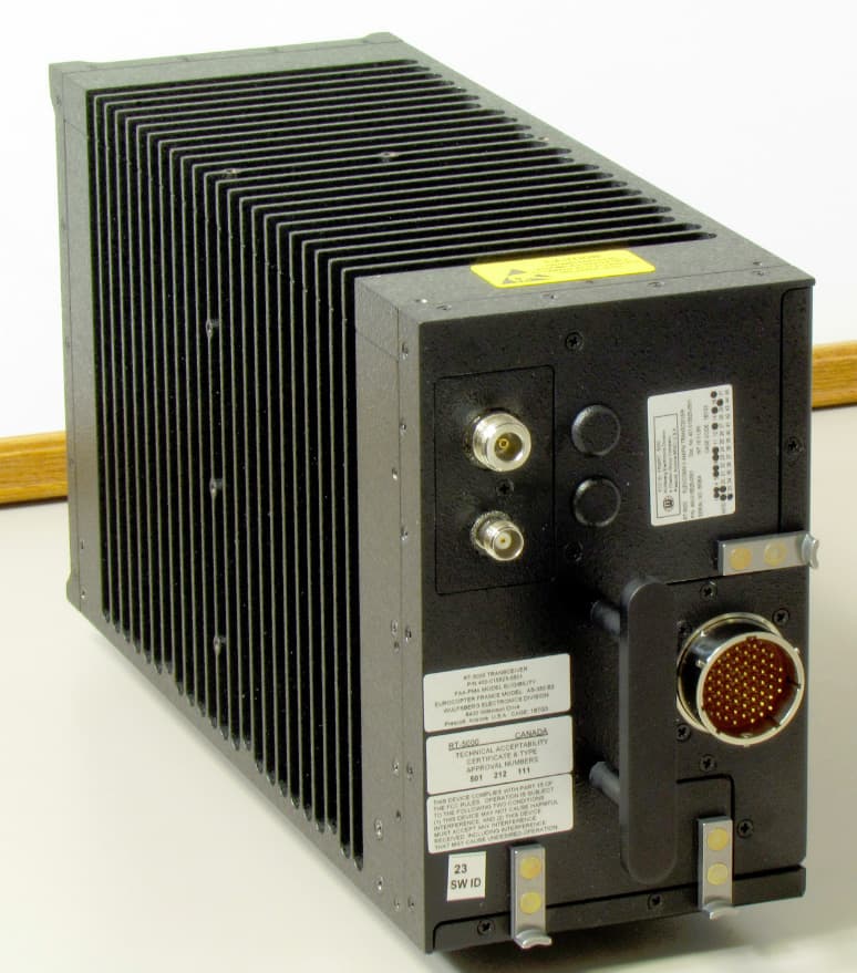
FRWRT-5000P-06
Dec 28, 201229.7 to 960 MHz Tactical Airborne Transceiver
Equipment Class
TNB - Licensed Non-Broadcast Station Transmitter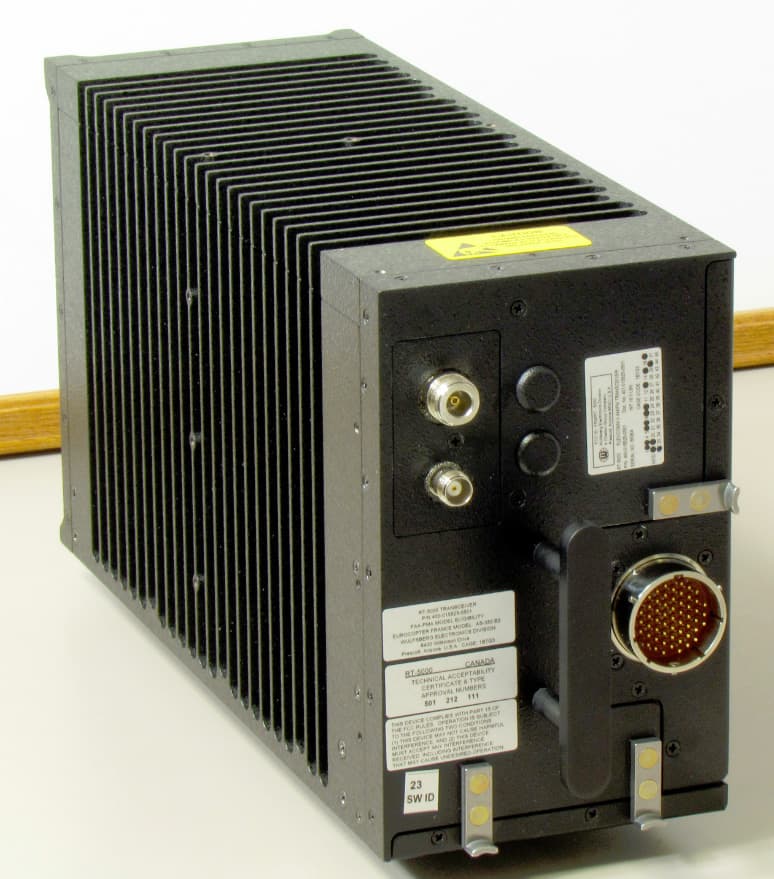
FRWRT-5000P-04
Dec 28, 201229.7 to 960 MHz Tactical Airborne Transceiver
Equipment Class
TNB - Licensed Non-Broadcast Station Transmitter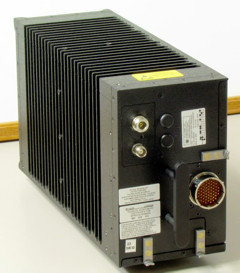
FRWRT-5000P-05
Dec 28, 201229.7 to 960 MHz Tactical Airborne Transceiver
Equipment Class
TNB - Licensed Non-Broadcast Station Transmitter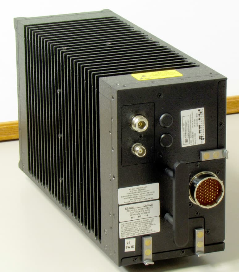
FRWRT-5000P-08
Dec 27, 201229.7 to 960 MHz Tactical Airborne Transceiver
Equipment Class
TNB - Licensed Non-Broadcast Station Transmitter