FRW2000-VHFAVHF Transceiver
Wulfsberg Electronics Division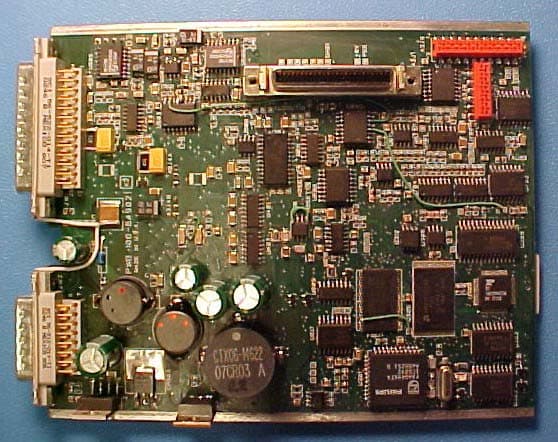
Click to zoom
Application Details
- Equipment Class
- TNB - Licensed Non-Broadcast Station Transmitter
- Date of Grant
- Sep 13, 2005
- Application Purpose
- Original Equipment
- Date of Application
- Sep 13, 2005
- Equipment Note
- VHF Transceiver
- Frequency Range
- 137.00000000 - 174.00000000
- Country
- United States
Documents & Files
Document Text
Text extracted from the exhibit documents filed with the FCC. Open a document above to read the original.
Users Manual
P-2000/C-2000/RT-2000 OPERATOR’S MANUAL Publication No. 150-049105 Page 2 of 40 Rev. C Operator’s Manual Jul 2005 P-2000 and C-2000/RT-2000 Transceiver Systems P-2000 Part Number: 400-049200-11-xxx-xxxx-xxxx Software Version: 1, Mod 4 C-2000 Part Number 400-049300-11-xxx Software Version: 1, Mod 4 RT-2000 Part Number 400-049400-11-xxx-xxxx-xxxx Software Version: 1, Mod 4 P-2000/C-2000/RT-2000 OPERATOR’S MANUAL Publication No. 150-049105 Page 3 of 40 Rev. C Operators Manual Jul 2005 TABLE OF CONTENTS INTRODUCTION .......................................................................................................................................................6 FEATURES..................................................................................................................................................................6 TRANSCEIVER OVERVIEW..........................................................................................................................................7 BASIC OPERATIONS................................................................................................................................................8 FRONT PANEL & CONTROLS.......................................................................................................................................8 KEYPAD BUTTONS......................................................................................................................................................9 THE HOME PAGE......................................................................................................................................................10 SETTING THE DISPLAY BRIGHTNESS.........................................................................................................................13 SETTING THE VOLUME LEVEL..................................................................................................................................13 SELECTING THE ACTIVE TRANSCEIVER....................................................................................................................14 SELECTING A STANDBY CHANNEL USING THE CURSOR/VALUE KNOB.....................................................................15 SELECTING A CHANNEL USING THE KEYPAD...........................................................................................................15 SELECTING A CHANNEL BY ALPHANUMERIC IDENTIFIER.........................................................................................16 USING THE DIRECT/REPEAT FEATURE......................................................................................................................16 RECEIVING/TRANSMITTING......................................................................................................................................17 ENABLING/DISABLING TRANSCEIVERS.....................................................................................................................17 QMEM OPERATIONS ............................................................................................................................................18 MESSAGE PAGE......................................................................................................................................................19 PROGRAMMING/EDITING A PRESET CHANNEL .........................................................................................21 EDITING A PRESET CHANNEL...................................................................................................................................22 CHANGING TRANSMIT POWER..................................................................................................................................22 ENHANCED SYSTEM FEATURES.......................................................................................................................23 RELAY MODE...........................................................................................................................................................23 SIMULCAST MODE....................................................................................................................................................24 RELAY/SIMULCAST MODE.......................................................................................................................................25 REPEATER MODE......................................................................................................................................................26 ENCRYPTION FEATURES ....................................................................................................................................27 TURNING ENCRYPTION ON AND OFF........................................................................................................................27 SELECTING AN ENCRYPTION KEY.............................................................................................................................27 PERFORMING AN OTAR ...........................................................................................................................................28 LOADING ENCRYPTION KEYS...................................................................................................................................30 ERASING ENCRYPTION KEYS WITH A KEY LOADER.................................................................................................31 CPS MODE ................................................................................................................................................................32 LOADING CHANNEL MEMORY..................................................................................................................................32 SYSTEM SETUP MODE..........................................................................................................................................35 MAINTENANCE PAGES ...............…
Text truncated - open the document above for the full version.
Users Manual
P-2000/C-2000/RT-2000 OPERATOR’S MANUAL Publication No. 150-049105 Page 4 of 40 Rev. C Operators Manual July 2005 RF Exposure Information This radio is restricted to occupational/controlled applications where users have been made aware of the potential for exposure and can exercise control over their exposure. Antennas used for the radio must not exceed the antenna gain shown below for each transmit frequency range. The antenna must be installed at least or exceeding the minimum distance away from any person(s) depending on the transmit frequency. Frequency Max Antenna Gain Min Distance 137 – 174 MHz 0 dBi 65 cm (25.6 in) 380 - 470 MHz 3 dBi 50 cm (19.7 in) 450 – 520 MHz 3 dBi 50 cm (19.7 in) 764 – 870 MHz 3 dBi 20 cm (7.9 in) Transmit no more than 50 % of the time. Measurable RF energy exposure occurs only when transmitting. Failure to observe these restrictions will result in exceeding the FCC RF exposure limits.
Cover Letter(s)
_____________________________________________________________________________________ July 28, 2005 Authorization & Evaluation Division Federal Communications Commission Laboratory 7435 Oakland Mills Road Columbia, MD 21046 Ladies and Gentlemen, Reference: Application for Certification of Transceiver with FCC ID: FRW2000-VHFA This equipment is available in two versions: a non-front panel programmable version and a front panel programmable version. The only difference between the two versions is in internal software. When a non-front panel programmable version is used, this equipment meets the requirements of 47 CFR 90.203(e). Programming of this product’s transmit frequencies can be performed only by the manufacturer, or by service or maintenance personnel. The operator cannot program transmit frequencies using the equipment’s external operation controls. When an operator front panel programmable version is used, use is restricted under 90.423 to operation on board aircraft. Please contact me at 928-708-1543 if you require any additional information. Regards, /S/ Mary Beaumont Mary Beaumont Principal RF Engineer Email: [email protected] Wulfsberg Electronics A Chelton Group Company 6400 Wilkinson Drive Prescott, AZ 86301-6164 USA Phone 1-928-708-1550 Fax 1-928-541-7627 www.Wulfsberg.com
Cover Letter(s)
_____________________________________________________________________________________ June 29, 2005 Authorization & Evaluation Division Federal Communications Commission Laboratory 7435 Oakland Mills Road Columbia, MD 21046 Subject: Confidentiality Request - Application for Certification of Transceiver with FCC ID: FRW2000-VHFA Ladies and Gentlemen: Wulfsberg Electronics is requesting that the Exhibits listed below be withheld from public view per the provisions of CFR 47 Part 0.459. Wulfsberg Electronics considers the information in these exhibits to be classified as trade secrets, pursuant to 47 CFR Part 0.457 (d). Release of such information could result in serious harm and the loss of company proprietary information. Exhibit 4 P-2000 Circuit Descriptions Exhibit 5 Schematic Diagrams Exhibit10 Part Lists Exhibit 12 Operational Description Please contact me if you require any additional information. Regards, /S/ Mary Beaumont Mary Beaumont Principal RF Engineer 928-708-1543 Email: [email protected] Wulfsberg Electronics A Chelton Group Company 6400 Wilkinson Drive Prescott, AZ 86301-6164 USA Phone 1-928-708-1550 Fax 1-928-541-7627 www.Wulfsberg.com
ID Label/Location Info
FRW2000-VHFA FCC Labels ID Label: NOTES: 1. MATERIAL: 156-040975 DIE CUT SPECIFICATION FOR CLUSTER 1 TAMPER PROOF PERMANENT LABELS OR 156-040963 STANDARD CUT TAMPER PROOF PERMANENT LABEL 2. LETTERS: BLACK THERMAL TRANSFER 3. BACKGROUND: SILVER (MATTE FINISH) 4. BORDER: BLACK 5. CORNER: ROUNDED .06 R Max 6. ARTWORK: USE DATAFILE LABEL IMAGE 156-049087-0Y.X.LBL (Y = DASH NUMBER VARIATION) (X = CURRENT REV OF THIS DOCUMENT) 7. THERMAL RIBBON: RHD TT BLK 80MM X 300M REVERSE 8. FILL IN FIELDS (e.g. UNIT DASH NUMBERS, SERIAL NUMBERS) TO BE MARKED PER 150-341005 “WORK INSTRUCTIONS FOR THERMAL LABELS” TAG NO. SIZE -05 .70” X 1.80” Compliance Label: RF Exposure Warning Label: Label size is 1.06 x 1.56 with no border. FCC/Canada Label Location Information (Top View Of Unit): Integrated Transceiver Module #2 FCC Label Integrated Transceiver Module #1 FCC Label FM #2 RF Output FM #1 RF Output Part Number Label Hardware Mod Status Industry Canada Label Software Mod Status FCC Part 15 Compliance Label (located on the bottom) Industry Canada Label RF Exposure Warning Label
Internal Photos
Internal Photos Of Complete Assembly All versions of the P-2000/C-2000/RT-2000 Use the same internal connections and shielding as shown below: Unit Completely Assembled - Top View Unit Opened Showing Connection between Power Supply and CPU Board Ribbon Cable. Also Blue RF cables run from ITM module to Power Amp Modules. Step 3: Remove Front Panel/Display Assembly to show Front Loading Connector and CPU Board Connection Via Cable Assembly. View of ITM modules located below the CPU board. The Black and Red wires provide 8VDC power to the ITM Modules. Step 4: Slide CPU Board Out To Reveal ITM Modules inside. Interconnect is accomplished with Flex-cables. One for each ITM Module. View of Flex-cables and Power cables from each ITM to the CPU Board Step 5: CPU board completely removed. One ITM and Cover has been removed from chassis. Step 6: ITM Cover removed reveals the ITM module inside with ribbon cable and blue RF cable. Step 7: ITM Module without Cover View of ITM end of the Flex-cable. View of Power cables on underside of ITM Step 8: System with covers removed from Power Amplifier Modules. Step 9: Both ITM Modules with covers removed Internal Photos Of Complete Assembly All versions of the P-2000/C-2000/RT-2000 Use the same internal connections and shielding as shown below: Unit Completely Assembled - Top View Unit Opened Showing Connection between Power Supply and CPU Board Ribbon Cable. Also Blue RF cables run from ITM module to Power Amp Modules. Step 3: Remove Front Panel/Display Assembly to show Front Loading Connector and CPU Board Connection Via Cable Assembly. View of ITM modules located below the CPU board. The Black and Red wires provide 8VDC power to the ITM Modules. Step 4: Slide CPU Board Out To Reveal ITM Modules inside. Interconnect is accomplished with Flex-cables. One for each ITM Module. View of Flex-cables and Power cables from each ITM to the CPU Board Step 5: CPU board completely removed. One ITM and Cover has been removed from chassis. Step 6: ITM Cover removed reveals the ITM module inside with ribbon cable and blue RF cable. Step 7: ITM Module without Cover View of ITM end of the Flex-cable. View of Power cables on underside of ITM Step 8: System with covers removed from Power Amplifier Modules. Step 9: Both ITM Modules with covers removed FRW2000-VHFA: Internal Photos CPU Board - Top View CPU Board - Bottom View Power Supply Board - Top View Power Supply Board - Bottom View VHF Power Amp - Top View VHF Power Amp Board - Bottom View Display Board - Top View Display Board - Bottom View Switch Board - Top View Switch Board - Bottom View VHF Integrated Transceiver Module - Top View VHF Integrated Transceiver Module - Bottom View VHF Integrated Transceiver Module: FCC ID- AZ489FT3804 VHF MHz Integrated Transceiver Module – Transceiver Board Top View VHF MHz Integrated Transceiver Module – Transceiver Board Bottom View VHF MHz Integrated Transceiver Module – Vocon Board Top View VHF MHz Integrated Transceiver Module – Vocon Board Bottom View FRW2000-VHFA: Internal Photos CPU Board - Top View CPU Board - Bottom View Power Supply Board - Top View Power Supply Board - Bottom View VHF Power Amp - Top View VHF Power Amp Board - Bottom View Display Board - Top View Display Board - Bottom View Switch Board - Top View Switch Board - Bottom View VHF Integrated Transceiver Module - Top View VHF Integrated Transceiver Module - Bottom View VHF Integrated Transceiver Module: FCC ID- AZ489FT3804 VHF MHz Integrated Transceiver Module – Transceiver Board Top View VHF MHz Integrated Transceiver Module – Transceiver Board Bottom View VHF MHz Integrated Transceiver Module – Vocon Board Top View VHF MHz Integrated Transceiver Module – Vocon Board Bottom View
RF Exposure Info
M. Flom Associates, Inc. 3356 North San Marcos Place, Suite 107 Chandler, Arizona 85225-7176 FCC ID: FRW2000-VHFA (480) 926-3100 phone, (480) 926-3598 fax MFA p0560004, d0580040 Environmental Assessment for Mobiles/Fixed Base Station for FCC ID: FRW2000-VHFA Model: VHF FM Transceiver to Federal Communications Commission 47 CFR 1.1310 (MPE) Radiofrequency Radiation Exposure Limits Date Of Report: August 21, 2005 On the Behalf of the Applicant: Wulfsberg Electronics Division At the Request of: P.O. 19404 Wulfsberg Electronics Division 6400 Wilkinson Drive Prescott, AZ 86301-6164 Attention of: Main: (928) 708-1550; Fax: (928) 541-7627 Mary Beaumont, Principal RF Engineer Direct (928) 708-1543 Email: [email protected] Supervised By: David E. Lee, Quality Assurance Manager M. Flom Associates, Inc. 3356 North San Marcos Place, Suite 107 Chandler, Arizona 85225-7176 FCC ID: FRW2000-VHFA (480) 926-3100 phone, (480) 926-3598 fax MFA p0560004, d0580040 Table of Contents Rule Description Page . Test Report 1 . Identification of the Equipment Under Test 2 . Standard Test Conditions and Engineering Practices 4 1.1310 Environmental Assessment 5 M. Flom Associates, Inc. 3356 North San Marcos Place, Suite 107 Page 1 of 7 Chandler, Arizona 85225-7176 FCC ID: FRW2000-VHFA (480) 926-3100 phone, (480) 926-3598 fax MFA p0560004, d0580040 Required information per ISO/IEC Guide 25-1990, paragraph 13.2: a) Test Report (Supplemental) b) Laboratory: (FCC: 31040/SIT) (Canada: IC 2044) M. Flom Associates, Inc. 3356 N. San Marcos Place, Suite 107 Chandler, AZ 85225 c) Report Number: d0580040 d) Client: Wulfsberg Electronics Division 6400 Wilkinson Drive Prescott, AZ 86301-6164 e) Identification: FCC ID: FRW2000-VHFA P-2000VHFA Radio Description: Mobile FM Transceiver f) EUT Condition: Not required unless specified in individual tests. g) Report Date: August 21, 2005 EUT Received: June 6 th , 2005 h, j, k): As indicated in individual tests. i) Sampling method: No sampling procedure used. l) Uncertainty: In accordance with MFA internal quality manual. m) Supervised by: David E. Lee, Quality Assurance Manager n) Results: The results presented in this report relate only to the item tested. o) Reproduction: This report must not be reproduced, except in full, without written permission from this laboratory. M. Flom Associates, Inc. 3356 North San Marcos Place, Suite 107 Page 2 of 7 Chandler, Arizona 85225-7176 FCC ID: FRW2000-VHFA (480) 926-3100 phone, (480) 926-3598 fax MFA p0560004, d0580040 Identification of the Equipment Under Test (EUT) Name and Address of Applicant: Wulfsberg Electronics Division 6400 Wilkinson Drive Prescott, AZ 86301-6164 Manufacturer: Wulfsberg Electronics Division 6400 Wilkinson Drive Prescott, AZ 86301-6164 FCC ID: FRW2000-VHFA Model Number: P-2000VHFA VHF Radio Description: Mobile FM Transceiver Type of Emission: FM, Digital Frequency Range, MHz: 137.000 to 174.000 Power Rating, Watts: 1 to 10 X Switchable Variable N/A Modulation: AMPS TDMA CDMA X OTHER Antenna: Helical Monopole X Whip X Other Note: For RF Safety test antenna gain taken at the upper range of expected gain (i.e. 0 dBd) and RF Power set to highest nominal power across all channels. M. Flom Associates, Inc. 3356 North San Marcos Place, Suite 107 Page 3 of 7 Chandler, Arizona 85225-7176 FCC ID: FRW2000-VHFA (480) 926-3100 phone, (480) 926-3598 fax MFA p0560004, d0580040 A2LA “A2LA has accredited M. Flom Associates, Inc. Chandler, AZ for technical competence in the field of Electrical Testing. The accreditation covers the specific tests and types of tests listed on the agreed scope of accreditation. This laboratory meets the requirements of ISO/IEC 17025 – 1999 ‘General Requirements for the Competence of Testing and Calibration Laboratories’ and any additional program requirements in the identified field of testing.” Certificate Number: 2152-01 NIST I am pleased to inform you that your laboratory has been validated by the Chinese Taipei Bureau of Standards, Metrology and Inspection (BSMI) under the Asia Pacific Economic Cooperation Mutual Recognition Agreement (APEC MRA). Your laboratory is now formally designated to act as a Conformity Assessment Body (CAB) under Appendix B, Phase I Procedures, of the APEC MRA between the American Institute in Taiwan (AIT) and the Taipei Economic and Cultural Representative Office (TECRO) in the United States, covering equipment subject to Electro-Magnetic Compatibility (EMC) requirements. The names of all validated and nominated laboratories will be posted on the NIST website at http://ts.nist.gov/mra under the ‘Asia’ category.” BSMI Number: SL2-IN-E-041R M. Flom Associates, Inc. 3356 North San Marcos Place, Suite 107 Page 4 of 7 Chandler, Arizona 85225-7176 FCC ID: FRW2000-VHFA (480) 926-3100 phone, (480) 926-3598 fax MFA p0560004, d0580040 Standard Test Conditions and Engineering Practices Except as noted herein, the following conditions and procedures were observed during the testing: In accordance with ANSI C63.4-1992/2000, section 6.1.9, and unless otherwise indicated in the specific measurement results, the ambient temperature of the actual EUT was maintained within the range of 10° to 40°C (50° to 104 °F) unless the particular equipment requirements specify testing over a different temperature range. Also, unless otherwise indicated, the humidity levels were in the range of 10% to 90% relative humidity. Prior to testing, the EUT was tuned up in accordance with the manufacturer's alignment procedures. All external gain controls were maintained at the position of maximum and/or optimum gain throughout the testing. Measurement results, unless otherwise noted, are worst-case measurements. M. Flom Associates, Inc. 3356 North San Marcos Place, Suite 107 Page 5 of 7 Chandler, Arizona 85225-7176 FCC ID: FRW2000-VHFA (480) 926-3100 phone, (480) 926-3598 fax MFA p0560004, d0580040 Name of Test: Environmental Assessment Specification: FCC: 47 CFR 1.1310 Measurement Guide: ANSI/IEEE C95.1 19…
Text truncated - open the document above for the full version.
Test Report
M. Flom Associates, Inc. 3356 North San Marcos Place, Suite 107 Chandler, Arizona 85225-7176 FCC ID: FRW2000-VHFA (480) 926-3100 phone, (480) 926-3598 fax MFA p0560004, d0560005 Date of Report: Date of Submission: June 16, 2005 September 2, 2005 Federal Communications Commission Via: Electronic Filing Attention: Authorization & Evaluation Division Applicant: Wulfsberg Electronics Division Equipment: P2000-VHF VHF/FM Radio FCC ID: FRW2000-VHFA FCC Rules: 80.379, 90, 90.210, Confidentiality Gentlemen: On behalf of the Applicant, enclosed please find Application Form 731, Engineering Test Report and all pertinent documentation, the whole for approval of the referenced equipment as shown. Filing fees are attached. We trust the same is in order. Should you need any further information, kindly contact the writer who is authorized to act as agent. Sincerely yours, Michael Schafer, President enclosure(s) cc: Applicant MS/del M. Flom Associates, Inc. 3356 North San Marcos Place, Suite 107 Chandler, Arizona 85225-7176 FCC ID: FRW2000-VHFA (480) 926-3100 phone, (480) 926-3598 fax MFA p0560004, d0560005 Transmitter Certification of Model: P2000-VHF VHF/FM Radio FCC ID: FRW2000-VHFA to Federal Communications Commission Rule Part(s) 80.379, 90, 90.210, Confidentiality Date of report: June 16, 2005 On the Behalf of the Applicant: Wulfsberg Electronics Division At the Request of: P.O. 19404 Wulfsberg Electronics Division 6400 Wilkinson Drive Prescott, AZ 86301-6164 Attention of: Main: (928) 708-1550; Fax: (928) 541-7627 Mary Beaumont, Principal RF Engineer Direct (928) 708-1543 Email: [email protected] Supervised by: Michael Findley, Laboratory Manager M. Flom Associates, Inc. 3356 North San Marcos Place, Suite 107 Chandler, Arizona 85225-7176 FCC ID: FRW2000-VHFA (480) 926-3100 phone, (480) 926-3598 fax MFA p0560004, d0560005 List of Exhibits (FCC Certification (Transmitters) - Revised 9/28/98) Applicant: Wulfsberg Electronics Division FCC ID: FRW2000-VHFA By Applicant: 1. Letter of Authorization 2. Confidentiality Request: 0.457 And 0.459 3. Part 90.203(e) & (g) Attestation 4. Identification Drawings, 2.1033(c)(11) Label Location of Label Compliance Statement Location of Compliance Statement 5. Photographs, 2.1033(c)(12) 6. Documentation: 2.1033(c) (3) User Manual (9) Tune Up Info (10) Schematic Diagram (10) Circuit Description Block Diagram Parts List Active Devices 7. MPE Report By M.F.A. Inc.: A. Testimonial & Statement of Certification M. Flom Associates, Inc. 3356 North San Marcos Place, Suite 107 Chandler, Arizona 85225-7176 FCC ID: FRW2000-VHFA (480) 926-3100 phone, (480) 926-3598 fax MFA p0560004, d0560005 The Applicant has been cautioned as to the following: 15.21 Information to the User. The users manual or instruction manual for an intentional radiator shall caution the user that changes or modifications not expressly approved by the party responsible for compliance could void the user's authority to operate the equipment. 15.27(a) Special Accessories. Equipment marketed to a consumer must be capable of complying with the necessary regulations in the configuration in which the equipment is marketed. Where special accessories, such as shielded cables and/or special connectors are required to enable an unintentional or intentional radiator to comply with the emission limits in this part, the equipment must be marketed with, i.e. shipped and sold with, those special accessories. However, in lieu of shipping or packaging the special accessories with the unintentional or intentional radiator, the responsible party may employ other methods of ensuring that the special accessories are provided to the consumer, without additional charge. Information detailing any alternative method used to supply the special accessories for a grant of equipment authorization or retained in the verification records, as appropriate. The party responsible for the equipment, as detailed in § 2.909 of this chapter, shall ensure that these special accessories are provided with the equipment. The instruction manual for such devices shall include appropriate instructions on the first page of text concerned with the installation of the device that these special accessories must be used with the device. It is the responsibility of the user to use the needed special accessories supplied with the equipment. M. Flom Associates, Inc. 3356 North San Marcos Place, Suite 107 Chandler, Arizona 85225-7176 FCC ID: FRW2000-VHFA (480) 926-3100 phone, (480) 926-3598 fax MFA p0560004, d0560005 Table of Contents Rule Description Page 2.1033(c)(14) Rule Summary 2 . Standard Test Conditions and Engineering Practices 3 2.1033(c) General Information Required 5 2.1046(a) Carrier Output Power (Conducted) 8 2.1053(a) Field Strength of Spurious Radiation 10 2.1049(c)(1) Emission Masks (Occupied Bandwidth) 17 90.214 Transient Frequency Behavior 30 2.1047(a) Audio Low Pass Filter (Voice Input) 36 2.1047(a) Audio Frequency Response 38 2.1047(b) Modulation Limiting 40 2.1055(a)(1) Frequency Stability (Temperature Variation) 43 2.1055(b)(1) Frequency Stability (Voltage Variation) 45 2.202(g) Necessary Bandwidth and Emission Bandwidth 47 M. Flom Associates, Inc. 3356 North San Marcos Place, Suite 107 Page 1 of 47 Chandler, Arizona 85225-7176 FCC ID: FRW2000-VHFA (480) 926-3100 phone, (480) 926-3598 fax MFA p0560004, d0560005 Required information per ISO/IEC Guide 25-1990, paragraph 13.2: a) Test Report b) Laboratory: (FCC: 31040/SIT) (Canada: IC 2044) M. Flom Associates, Inc. 3356 N. San Marcos Place, Suite 107 Chandler, AZ 85225 c) Report Number: d0560005 d) Client: Wulfsberg Electronics Division 6400 Wilkinson Drive Prescott, AZ 86301-6164 e) Identification: P2000-VHF VHF/FM Radio FCC ID: FRW2000-VHFA EUT Description: Mobile FM Transceiver f) EUT Condition: Not required unless specified in individual tests. g) Report Date: June 16, 2005 EUT Received: June 6, 2005 h, j, k): As indicated in individual tests. i) Sampling method: No sampling pro…
Text truncated - open the document above for the full version.
Contact Information
Applicant
James F Buehring(Certification Manager)
Technical Contact
M. Flom Associates, Inc.David Lee
[email protected]480-926-3100
3356 N. San Marcos Place, Suite 107 · Chandler, Arizona · United States
Test Firm
Compliance Testing, LLCMichael Schafer
Technical Specifications
| # | Rule Parts | Frequency Range | Power Output | Emission | Tolerance |
|---|---|---|---|---|---|
| 1 | 80,9 | 137 MHz - 174 MHz | 10 W | 20K0F1E | 2.5 ppm |
Other Applications from Wulfsberg Electronics Division
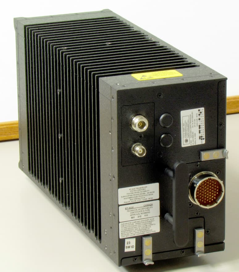
FRWRT-5000P-03
Dec 28, 201229.7 to 960 MHz Tactical Airborne Transceiver
Equipment Class
TNB - Licensed Non-Broadcast Station Transmitter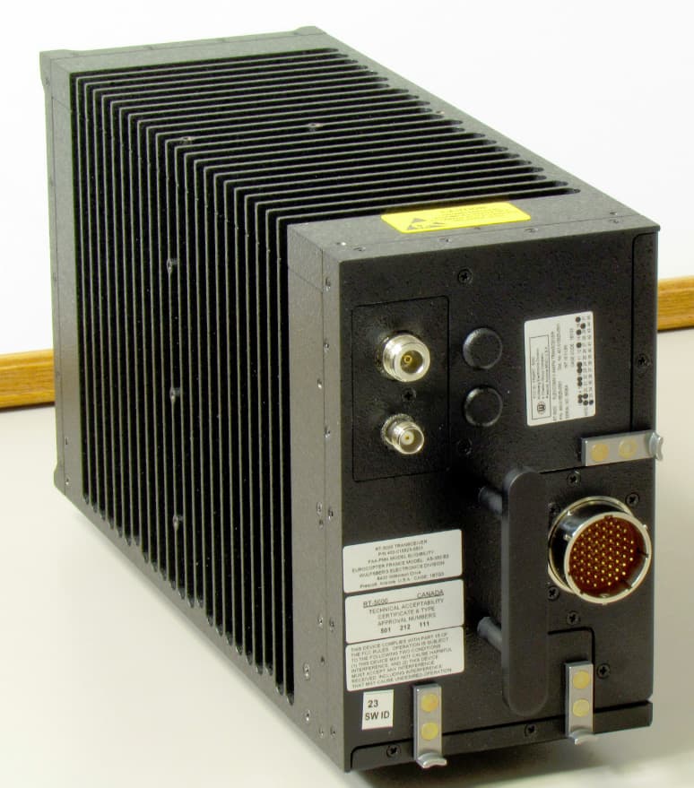
FRWRT-5000P-06
Dec 28, 201229.7 to 960 MHz Tactical Airborne Transceiver
Equipment Class
TNB - Licensed Non-Broadcast Station Transmitter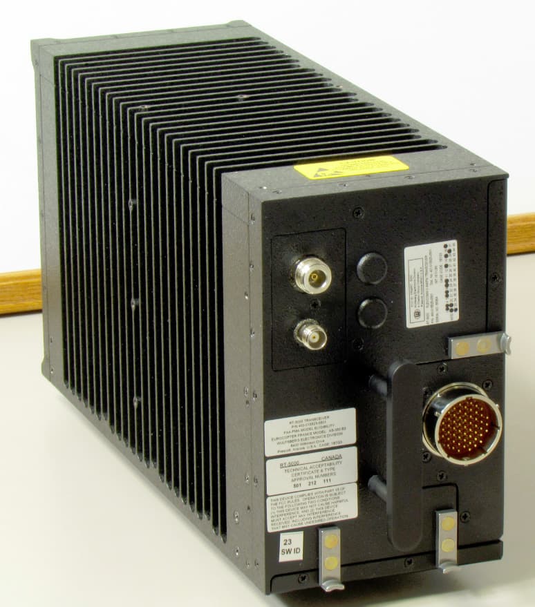
FRWRT-5000P-04
Dec 28, 201229.7 to 960 MHz Tactical Airborne Transceiver
Equipment Class
TNB - Licensed Non-Broadcast Station Transmitter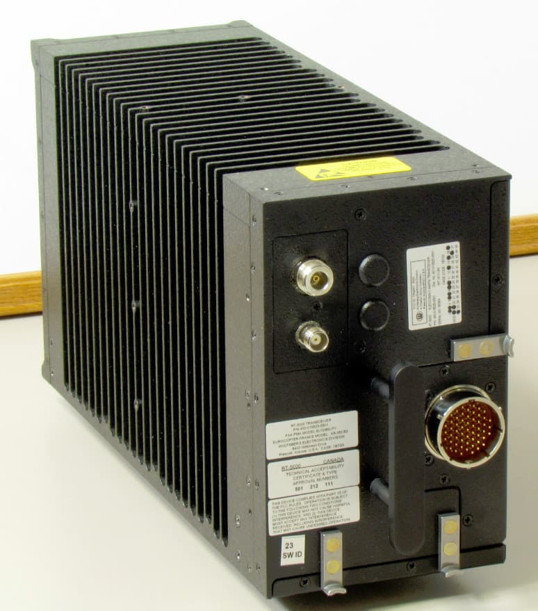
FRWRT-5000P-05
Dec 28, 201229.7 to 960 MHz Tactical Airborne Transceiver
Equipment Class
TNB - Licensed Non-Broadcast Station Transmitter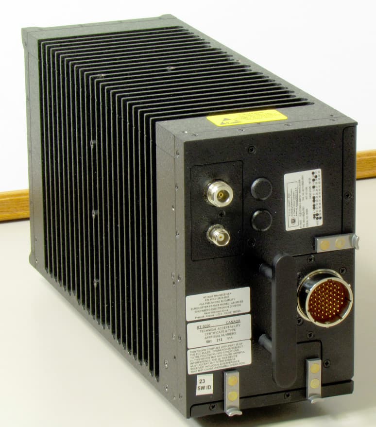
FRWRT-5000P-08
Dec 27, 201229.7 to 960 MHz Tactical Airborne Transceiver
Equipment Class
TNB - Licensed Non-Broadcast Station Transmitter