FRWCDM-451FLITELINE DISTANCE MEASURING SYSTEM
Wulfsberg Electronics Division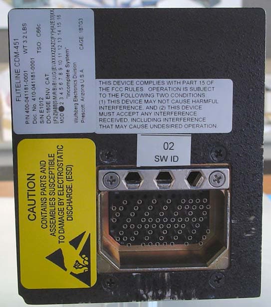
Click to zoom
Application Details
- Equipment Class
- TNB - Licensed Non-Broadcast Station Transmitter
- Date of Grant
- Aug 27, 2006
- Application Purpose
- Original Equipment
- Date of Application
- Aug 27, 2006
- Equipment Note
- FLITELINE DISTANCE MEASURING SYSTEM
- Frequency Range
- 1025.00000000 - 1150.00000000
- Country
- United States
Documents & Files
Document Text
Text extracted from the exhibit documents filed with the FCC. Open a document above to read the original.
Users Manual
APPLICATION REVISIONS REV B NEXT ASSEMBLY FINAL ASSEMBLY REV DESCRIPTION DATE APPROVED APPROVED A Initial Release per DCN W2819 3-23-04 S Wagner R Talken SH 1 B Revised per DCN W5376 7/12/06 S. Wagner D. Woodhurst DWG. NO. 150-041762 THIS COVER SHEET IS FOR WULFSBERG ELECTRONICS INTERNAL USE. IT IS NOT TO BE PUBLISHED WITH THE DOCUMENT IT DESCRIBES THIS DOCUMENT CONTAINS PROPRIETARY INFORMATION OF WULFSBERG ELECTRONICS, A COBHAM AVIONICS & SURVEILLANCE GROUP COMPANY, NEITHER RECEIPT NOR POSSESSION THEREOF CONFERS ANY RIGHT TO REPRODUCE OR USE, OR DISCLOSE, IN WHOLE OR IN PART, ANY SUCH INFORMATION WITHOUT WRITTEN AUTHORIZATION FROM WULFSBERG ELECTRONICS APPROVALS DATE DRAWN C Gregory 11-24-03 CHECKED K Snodgrass 3-17-04 OPERATION MANUAL, CDM-451 ENGINEER S Wagner 3-16-04 ISSUED R Talken 3-23-04 SIZE A CAGE CODE 1B7G3 DWG NO. 150-041762 REV B Typed signatures indicate approval. Handwritten signature approval of this document is on file at Wulfsberg Electronics, Prescott, Arizona. SCALE: NONE DO NOT SCALE DRAWING This page intentionally left blank. CDM-451 DISTANCE MEASURING SYSTEM OPERATOR’S MANUAL Wulfsberg Electronics, A Cobham Avionics & Surveillance Group Company, located in Prescott, Arizona, designs and manufactures the Wulfsberg Electronics FliteLine™ suite of products, including the CDM-451 Distance Measuring System. For more than 25 years, Wulfsberg Electronics has distinguished itself by providing top quality avionics products for civil, air transport, and military applications. Wulfsberg Electronics makes no warranty, expressed or implied, with regard to this manual, including but not limited to any implied warranties of merchantability, fitness for a particular purpose, and non- infringement. In addition, Wulfsberg Electronics makes no warranty with regard to the documentation or data contained herein. Wulfsberg Electronics is not liable in the event of incidental, special, consequential, or any other damages in connection with or arising from furnishing, performance, or use of this manual. Reproduction of this publication or any portion thereof by any means is prohibited. For further information contact Sales, Wulfsberg Electronics, 6400 Wilkinson Drive, Prescott, Arizona, 86301. Telephone: (928) 708-1500. Information in this manual is subject to change without notice. © 2001 Wulfsberg Electronics All rights reserved FliteLine™, FliteDME™, CDM-451 and SD-442B are trademarks of Wulfsberg Electronics. PROPRIETARY NOTICE This document contains proprietary information and such information may not be disclosed to others for any purpose, nor used for manufacturing purposes without written permission from Wulfsberg Electronics. Page 2 Publication No. 150-041762 Operator’s Manual Rev. B July 2006 CDM-451 DISTANCE MEASURING SYSTEM OPERATOR’S MANUAL 1. General This section describes the displays and controls of the FliteDME Distance Measuring System. The FliteDME System requires the use of a frequency tuning unit, such as the VNS 41A VHF Navigation System, or other ARINC 429 tuning control unit. However, if the CDM-451 being used is a 400-041181-0012/0112 part number, then King Serial tuning information can be supplied via the KDI-572, part number 066-1069-15. An aircraft audio system, including headphones and/or speaker amplifier and speaker, is required to process DME ident audio outputs. 2. Operation All controls and displays used to operate the FliteDME Distance Measuring System are located on the SD-442B Selector-Display or the KDI-572 Master Indicator. Refer to Figure 1 and Figure 2 for the following discussions: A. SD-442B Selector-Display Figure 1. SD-442B Control and Display Functions (1) NAV PUSHBUTTON selects the NAV 1, NAV 2, or RNAV frequency tuning source. A1, 2, or RNV is displayed in the lower left corner of the display window, to annunciate the tuning source. (2) HLD PUSHBUTTON holds the last frequency selected by the NAV< freeing the NAV receiver to change frequency. The frequency to which the DME is tuned is displayed in the right portion of the display window, with HLD and FRQ annunciated. If the SD-442B is strapped as an RNAV repeater, RNV flashes for RNAV related functions when the HLD button is pressed. Publication No. 150-041762 Page 3 Rev. B Operator’s Manual July 2006 CDM-451 DISTANCE MEASURING SYSTEM OPERATOR’S MANUAL (3) TTS PUSHBUTTON displays the time-to-station in hours and minutes, from 0 to 8 hours, in the right portion of the display window, when pressed. TTS annunciates below time. The ground speed display returns when the TTS pushbutton is released. (4) DISTANCE DISPLAY shows distance to station in nautical miles. From 0 to 99.9 nautical miles, the distance is displayed in one tenth mile increments. From 100 to 300 nautical miles, the distance is displayed in one nautical mile increments. (5) GROUND SPEED DISPLAY shows ground speed from 25 to 800 knots in 1 knot increments. (6) The audio circuits will scan NAV 1 and NAV 2 stations for DME audio identification. When an audio signal is detected the audio ident signal will appear on the aircraft’s audio system, on the selected NAV/DME combination (DME 1 or 2). (7) The system can accommodate an optional RNAV/VOR mode switch for the display of RNAV distance to waypoint, and ground speed, or time-to-station when in the RNAV mode. B. KDI-572 Master Indicator Figure 2. KDI-572 (P/N 066-1069-15) Control and Display Functions (1) The FUNCTION SWITCH on the front of the KDI-572 has three positions OFF, ON, and HLD. In the OFF position, the master indicator and the remote mounted DME are turned off. In the ON position, the DME is channeled from the NAV 1 control head. In the HLD position, the DME is channeled to the last selected NAV 1 frequency. To prevent the display of false information, the KDI-572 will display dashes and the CDM-451 will stay in “search”, whenever power is turned on, or momentarily interrupted in frequency HLD mode. Normal operation is re-established by switching to the ON position. (2) The…
Text truncated - open the document above for the full version.
Cover Letter(s)
6400 Wilkinson Drive Prescott, AZ 86301-6164 USA Phone 1-928-708-1550 Fax 1-928-541-7627 www.Wulfsberg.com Wulfsberg Electronics Cobham Avionics & Surveillance Date: July 27, 2006 Federal Communications Commission Equipment Approval Services P.O. Box 358315 Pittsburgh, PA 15251-5315 Attn: Authorization and Evaluation Division PER: 47 CFR 0.457 and 0.459 RE: FRWCDM-451 Pursuant to Sections 0.457(d)(1)(ii) and 0.459 of the Commission's Rules, the Applicant hereby requests confidential treatment of some of the information accompanying this Application as listed below, i.e. Active Devices Alignment Block Diagrams Parts Lists Schematics Theory of Operation These materials contain trade secrets and proprietary information not customarily released to the public and the public disclosure of these matters might be harmful to the Applicant and provide unjustified benefits to its competitors. The Applicant understands that pursuant to Rule 0.457(d)(1)(ii) disclosure of this Application and all accompanying documentation will not be made before the date of the Grant for this Application. Sincerely, Vern D. Wallace Product Certification Manager Wulfsberg Electronics
External Photos
Page 1 of 16 CDM-451 Distance Measuring Equipment Page 2 of 16 CDM-451 External Photos Proposed FCC label Page 3 of 16 CDM-451 External Photos
ID Label/Location Info
Page 2 of 16 CDM-451 External Photos Proposed FCC label
Internal Photos
Page 4 of 16 CDM-451 internal Photos Page 5 of 16 CDM-451 internal Photos Page 6 of 16 CDM-451 internal Photos Page 7 of 16 CDM-451 internal Photos Page 8 of 16 CDM-451 Circuit Board Photos 310-041133-01 R/T Board Top Side Page 9 of 16 CDM-451 Circuit Board Photos 310-041133-01 R/T Board Top Side with Shield Page 10 of 16 CDM-451 Circuit Board Photos 310-041133-01 R/T Board Bottom Side Page 11 of 16 CDM-451 Circuit Board Photos 310-041153-01 Power Supply/Modulator Board Top Side Page 12 of 16 CDM-451 Circuit Board Photos 310-041153-01 Power Supply/Modulator Board Bottom Side Page 13 of 16 CDM-451 Circuit Board Photos 310-041186-01 Processor Board Top Side Page 14 of 16 CDM-451 Circuit Board Photos 310-041186-01 Processor Board Bottom Side Page 15 of 16 CDM-451 Circuit Board Photos 310-041185 Interconnect Board Top Side Page 16 of 16 CDM-451 Circuit Board Photos 310-041185 Interconnect Board Bottom Side
RF Exposure Info
Flom Test Labs 3356 N. San Marcos Place, Suite 107 Chandler, Arizona 85225-7176 FCC ID: FRWCDM-451 (866) 311-3268 phone, (480) 926-3598 fax MFA p0660016, d0670029 Environmental Assessment for Mobiles/Fixed Base Station for FCC ID: FCC ID: FRWCDM-451 Model: CDM 451 to Federal Communications Commission 47 CFR 1.1310 (MPE) Radiofrequency Radiation Exposure Limits Date Of Report: July 20, 2006 On the Behalf of the Applicant: Wulfsberg Electronics Division At the Request of: Wulfsberg Electronics Division 6400 Wilkinson Drive Prescott, AZ 86301-6164 Attention of: Main: (928) 708-1550; Fax: (928) 541-7627 Steve Wagner Email: [email protected] Sincerely yours, David McPherson, Compliance Engineer Flom Test Labs 3356 N. San Marcos Place, Suite 107 Chandler, Arizona 85225-7176 FCC ID: FRWCDM-451 (866) 311-3268 phone, (480) 926-3598 fax MFA p0660016, d0670029 Table of Contents Rule Description Page . Test Report 1 . Identification of the Equipment Under Test 2 . Standard Test Conditions and Engineering Practices 3 1.1310 Environmental Assessment 4 Flom Test Labs 3356 N. San Marcos Place, Suite 107 Page 1 of 4 Chandler, Arizona 85225-7176 FCC ID: FRWCDM-451 (866) 311-3268 phone, (480) 926-3598 fax MFA p0660016, d0670029 Required information per ISO/IEC Guide 25-1990, paragraph 13.2: a) Test Report (Supplemental) b) Laboratory: (FCC: 31040/SIT) (Canada: IC 2044) M. Flom Associates, Inc. 3356 N. San Marcos Place, Suite 107 Chandler, AZ 85225 c) Report Number: d0670029 d) Client: Wulfsberg Electronics Division 6400 Wilkinson Drive Prescott, AZ 86301-6164 e) Identification: CDM 451 FCC ID: FRWCDM-451 Description: DME f) EUT Condition: Not required unless specified in individual tests. g) Report Date: July 20, 2006 h, j, k): As indicated in individual tests. i) Sampling method: No sampling procedure used. l) Uncertainty: In accordance with MFA internal quality manual. m) Supervised by: David McPherson, Compliance Engineer n) Results: The results presented in this report relate only to the item tested. o) Reproduction: This report must not be reproduced, except in full, without written permission from this laboratory. Flom Test Labs 3356 N. San Marcos Place, Suite 107 Page 2 of 4 Chandler, Arizona 85225-7176 FCC ID: FRWCDM-451 (866) 311-3268 phone, (480) 926-3598 fax MFA p0660016, d0670029 Identification of the Equipment Under Test (EUT) Name and Address of Applicant: Wulfsberg Electronics Division 6400 Wilkinson Drive Prescott, AZ 86301-6164 Manufacturer: Wulfsberg Electronics Division 6400 Wilkinson Drive Prescott, AZ 86301-6164 FCC ID: FRWCDM-451 Model Number: CDM 451 Description: Type of Emission: 1M00P0N Frequency Range, MHz: 1025 to 1150 Power Rating, Watts: 250.0 (min) Switchable Variable x N/A Note: For RF Safety test antenna gain taken at the upper range of expected gain (i.e. 0 dBd) and RF Power set to highest nominal power across all channels. Flom Test Labs 3356 N. San Marcos Place, Suite 107 Page 3 of 4 Chandler, Arizona 85225-7176 FCC ID: FRWCDM-451 (866) 311-3268 phone, (480) 926-3598 fax MFA p0660016, d0670029 Standard Test Conditions and Engineering Practices Except as noted herein, the following conditions and procedures were observed during the testing: In accordance with ANSI C63.4-1992/2000, section 6.1.9, and unless otherwise indicated in the specific measurement results, the ambient temperature of the actual EUT was maintained within the range of 10° to 40°C (50° to 104 °F) unless the particular equipment requirements specify testing over a different temperature range. Also, unless otherwise indicated, the humidity levels were in the range of 10% to 90% relative humidity. Prior to testing, the EUT was tuned up in accordance with the manufacturer's alignment procedures. All external gain controls were maintained at the position of maximum and/or optimum gain throughout the testing. Measurement results, unless otherwise noted, are worst-case measurements. A2LA “A2LA has accredited M. Flom Associates, Inc. Chandler, AZ for technical competence in the field of Electrical Testing. The accreditation covers the specific tests and types of tests listed on the agreed scope of accreditation. This laboratory meets the requirements of ISO/IEC 17025 – 1999 ‘General Requirements for the Competence of Testing and Calibration Laboratories’ and any additional program requirements in the identified field of testing.” Certificate Number: 2152-01 Flom Test Labs 3356 N. San Marcos Place, Suite 107 Page 4 of 4 Chandler, Arizona 85225-7176 FCC ID: FRWCDM-451 (866) 311-3268 phone, (480) 926-3598 fax MFA p0660016, d0670029 Name of test: Environmental Assessment Specification: FCC: 47 CFR 1.1310 MPE Calculated Limit = 50Watts/m 2 (Occupational/Conducted) Power Conducted = 457 w Peak Minimum Safe Distance (Occupational/Controlled) Rm = [457/(12.56 x 50)] 1/2 = 1.43 meters (457 W, Peak) Calculated By: David McPherson, Compliance Engineer Flom Test Labs 3356 N. San Marcos Place, Suite 107 Chandler, Arizona 85225-7176 FCC ID: FRWCDM-451 (866) 311-3268 phone, (480) 926-3598 fax MFA p0660016, d0670029 (The following will be placed in the Instruction Manual) Mandatory Safety Instructions to Installers & Users Use only manufacturer or dealer supplied antenna. Antenna Minimum Safe Distance: 1.43 meters. Antenna Gain: zero dBd referenced to a dipole. The Federal Communications Commission has adopted a safety standard for human exposure to RF (Radio Frequency) energy which is below the OSHA (Occupational Safety and Health Act) limits. Antenna Mounting: The antenna supplied by the manufacturer or radio dealer must not be mounted at a location such that during radio transmission, any person or persons can come closer than the above indicated minimum safe distance to the antenna i.e. 1.43 meters. To comply with current FCC RF Exposure limits, the antenna must be installed at or exceeding the minimum safe distance shown above, and in accordance with the requirements of the antenna manufacturer or supplier. Base S…
Text truncated - open the document above for the full version.
Test Report
Flom Test Labs 3356 N. San Marcos Place, Suite 107 Chandler, Arizona 85225-7176 FCC ID: FRWCDM-451 (866) 311-3268 phone, (480) 926-3598 fax MFA p0660016, d0660031 Date of Report: Date of Submission: June 29, 2006 July 19, 2006 Federal Communications Commission Via: Electronic Filing Attention: Authorization & Evaluation Division Applicant: Wulfsberg Electronics Division Equipment: CDM-451 FCC ID: FRWCDM-451 FCC Rules: 87.187(O), 87.0(Q), 87.475, Confidentiality Gentlemen: On behalf of the Applicant, enclosed please find Application Form 731, Engineering Test Report and all pertinent documentation, the whole for approval of the referenced equipment as shown. Filing fees are attached. We trust the same is in order. Should you need any further information, kindly contact the writer who is authorized to act as agent. Sincerely yours, David McPherson, Compliance Engineer enclosure(s) cc: Applicant DEL/ca Flom Test Labs 3356 N. San Marcos Place, Suite 107 Chandler, Arizona 85225-7176 FCC ID: FRWCDM-451 (866) 311-3268 phone, (480) 926-3598 fax MFA p0660016, d0660031 Transmitter Certification of FCC ID: FRWCDM-451 Model: CDM-451 to Federal Communications Commission Rule Parts 87.187(O), 87.0(Q), 87.475 Date of report: June 29, 2006 On the Behalf of the Applicant: Wulfsberg Electronics Division At the Request of: Wulfsberg Electronics Division 6400 Wilkinson Drive Prescott, AZ 86301-6164 Attention of: Main: (928) 708-1550; Fax: (928) 541-7627 Steve Wagner Email: [email protected] Supervised by: David McPherson, Compliance Engineer Flom Test Labs 3356 N. San Marcos Place, Suite 107 Chandler, Arizona 85225-7176 FCC ID: FRWCDM-451 (866) 311-3268 phone, (480) 926-3598 fax MFA p0660016, d0660031 List of Exhibits (FCC Certification (Transmitters) - Revised 9/28/98) Applicant: Wulfsberg Electronics Division FCC ID: FRWCDM-451 By Applicant: 1. Letter of Authorization 2. Confidentiality Request: 0.457 And 0.459 3. Identification Drawings, 2.1033(c)(11) Label Location of Label Compliance Statement Location of Compliance Statement 4. Photographs, 2.1033(c)(12) 5. Documentation: 2.1033(c) (3) User Manual (9) Tune Up Info (10) Schematic Diagram (10) Circuit Description Block Diagram Parts List Active Devices By M.F.A. Inc.: A. Testimonial & Statement of Certification Flom Test Labs 3356 N. San Marcos Place, Suite 107 Chandler, Arizona 85225-7176 FCC ID: FRWCDM-451 (866) 311-3268 phone, (480) 926-3598 fax MFA p0660016, d0660031 The Applicant has been cautioned as to the following: 15.21 Information to the User. The users manual or instruction manual for an intentional radiator shall caution the user that changes or modifications not expressly approved by the party responsible for compliance could void the user's authority to operate the equipment. 15.27(a) Special Accessories. Equipment marketed to a consumer must be capable of complying with the necessary regulations in the configuration in which the equipment is marketed. Where special accessories, such as shielded cables and/or special connectors are required to enable an unintentional or intentional radiator to comply with the emission limits in this part, the equipment must be marketed with, i.e. shipped and sold with, those special accessories. However, in lieu of shipping or packaging the special accessories with the unintentional or intentional radiator, the responsible party may employ other methods of ensuring that the special accessories are provided to the consumer, without additional charge. Information detailing any alternative method used to supply the special accessories for a grant of equipment authorization or retained in the verification records, as appropriate. The party responsible for the equipment, as detailed in § 2.909 of this chapter, shall ensure that these special accessories are provided with the equipment. The instruction manual for such devices shall include appropriate instructions on the first page of text concerned with the installation of the device that these special accessories must be used with the device. It is the responsibility of the user to use the needed special accessories supplied with the equipment. Flom Test Labs 3356 N. San Marcos Place, Suite 107 Chandler, Arizona 85225-7176 FCC ID: FRWCDM-451 (866) 311-3268 phone, (480) 926-3598 fax MFA p0660016, d0660031 Table of Contents Rule Description Page 2.1033(c)(14) Rule Summary 2 . Standard Test Conditions and Engineering Practices 3 2.1033(c) General Information Required 4 2.1046(a) Carrier Output Power (Conducted) 6 2.1046(a) RF Power Output (Radiated) 8 2.1051 Unwanted Emissions (Transmitter Conducted) 9 2.1053(a) Field Strength of Spurious Radiation 11 2.1049(c)(1) Emission Masks (Occupied Bandwidth) 15 2.1055(a)(1) Frequency Stability (Temperature Variation) 22 2.1055(b)(1) Frequency Stability (Voltage Variation) 25 2.202(g) Necessary Bandwidth and Emission Bandwidth 27 Flom Test Labs 3356 North San Marcos Place, Suite 107 Page 1 of 27 Chandler, Arizona 85225-7176 FCC ID: FRWCDM-451 (866) 311-3268 phone, (480) 926-3598 fax MFA p0660016, d0660031 Required information per ISO/IEC Guide 25-1990, paragraph 13.2: a) Test Report b) Laboratory: (FCC: 31040/SIT) (Canada: IC 2044) M. Flom Associates, Inc. 3356 N. San Marcos Place, Suite 107 Chandler, AZ 85225 c) Report Number: d0660031 d) Client: Wulfsberg Electronics Division 6400 Wilkinson Drive Prescott, AZ 86301-6164 e) Identification: CDM-451 FCC ID: FRWCDM-451 EUT Description: DME f) EUT Condition: Not required unless specified in individual tests. g) Report Date: June 29, 2006 EUT Received: h, j, k): As indicated in individual tests. i) Sampling method: No sampling procedure used. l) Uncertainty: In accordance with MFA internal quality manual. m) Supervised by: David McPherson, Compliance Engineer n) Results: The results presented in this report relate only to the item tested. o) Reproduction: This report must not be reproduced, except in full, without written permission from this laboratory. Flom Test La…
Text truncated - open the document above for the full version.
Contact Information
Applicant
James F Buehring(Certification Manager)
Test Firm
Compliance Testing, LLCMichael Schafer
Technical Specifications
| # | Rule Parts | Frequency Range | Power Output | Emission | Tolerance |
|---|---|---|---|---|---|
| 1 | 87 | 1.02 GHz - 1.15 GHz | 457 W | 1M00P0N | 92.5900000000 ppm |
Other Applications from Wulfsberg Electronics Division
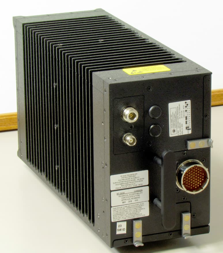
FRWRT-5000P-03
Dec 28, 201229.7 to 960 MHz Tactical Airborne Transceiver
Equipment Class
TNB - Licensed Non-Broadcast Station Transmitter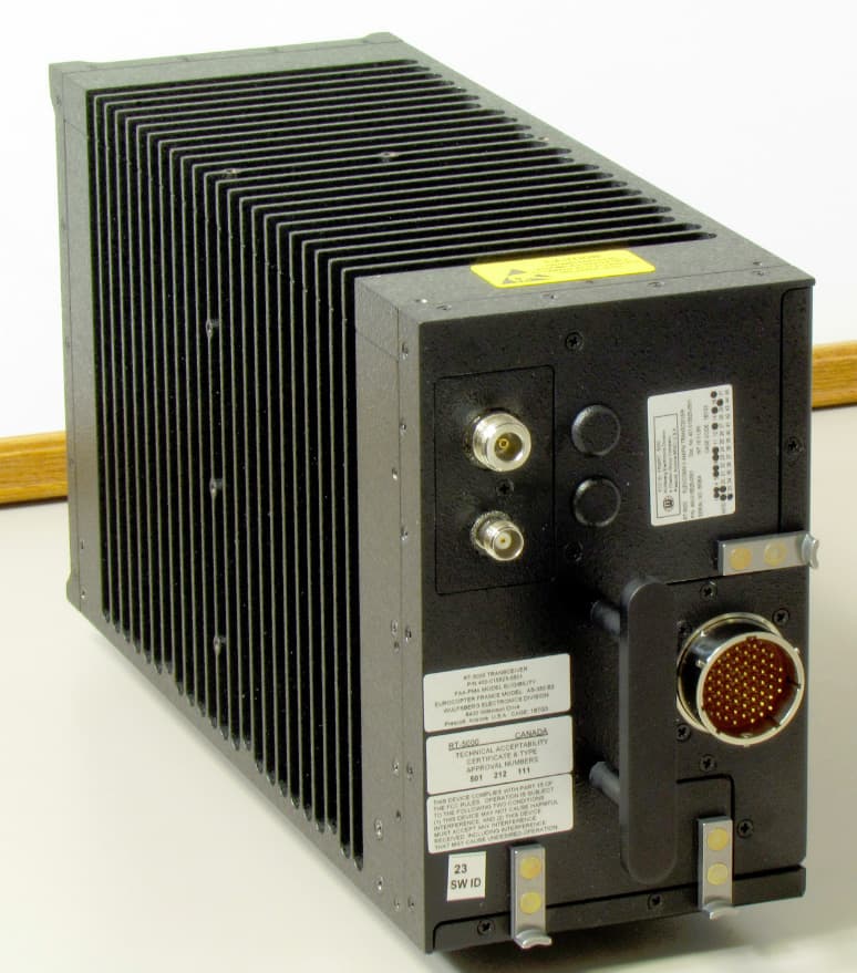
FRWRT-5000P-06
Dec 28, 201229.7 to 960 MHz Tactical Airborne Transceiver
Equipment Class
TNB - Licensed Non-Broadcast Station Transmitter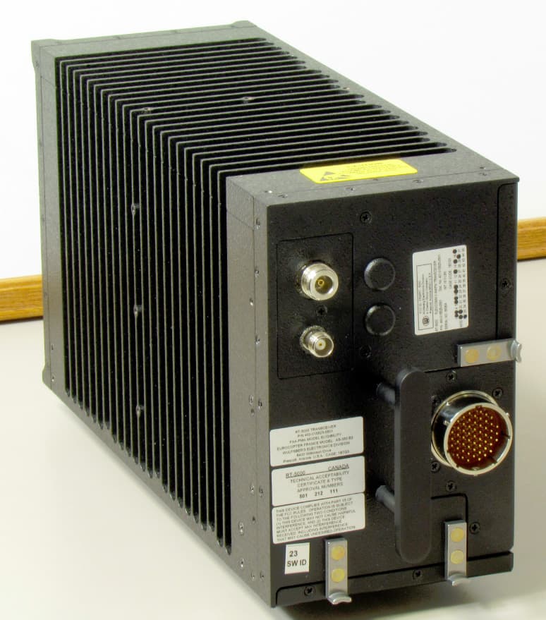
FRWRT-5000P-04
Dec 28, 201229.7 to 960 MHz Tactical Airborne Transceiver
Equipment Class
TNB - Licensed Non-Broadcast Station Transmitter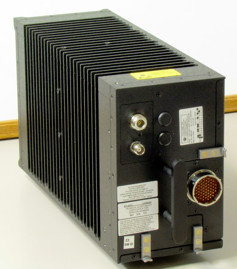
FRWRT-5000P-05
Dec 28, 201229.7 to 960 MHz Tactical Airborne Transceiver
Equipment Class
TNB - Licensed Non-Broadcast Station Transmitter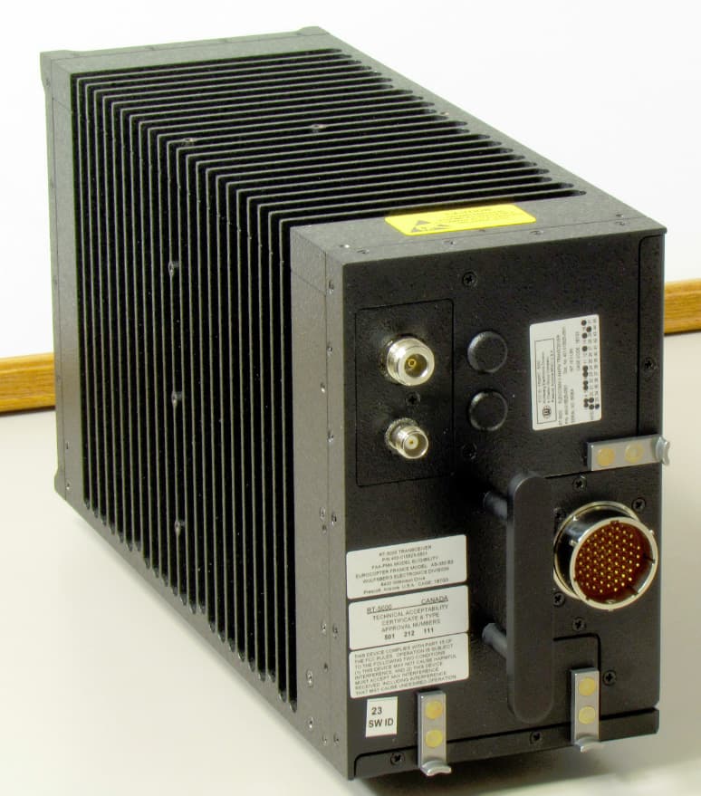
FRWRT-5000P-08
Dec 27, 201229.7 to 960 MHz Tactical Airborne Transceiver
Equipment Class
TNB - Licensed Non-Broadcast Station Transmitter