FRWRT-5000RT-5000 Aircraft Transceiver
Wulfsberg Electronics Division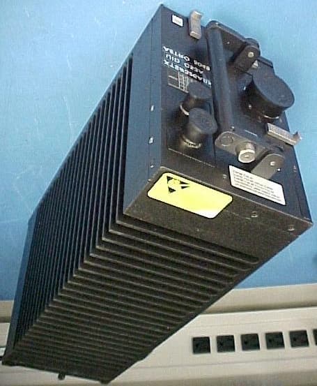
Click to zoom
Application Details
- Equipment Class
- TNB - Licensed Non-Broadcast Station Transmitter
- Date of Grant
- Jul 01, 2002
- Application Purpose
- Original Equipment
- Date of Application
- Mar 07, 2002
- Equipment Note
- RT-5000 Aircraft Transceiver
- Frequency Range
- 896.00000000 - 940.00000000
- Country
- United States
Documents & Files
Document Text
Text extracted from the exhibit documents filed with the FCC. Open a document above to read the original.
Users Manual
Operator’s Manual C-5000 COMMUNICATION MANAGEMENT CONTROLLER Part Number 31300-1X02-1XX0 Manual Number 150-041102 Revision A September 18, 2001 C-5000 Operatorís Manual 150-041102 REV. APage 2 of 61 TABLE OF CONTENTS INTRODUCTION .......................................................................................................................................................4 F EATURES ...................................................................................................................................................................4 T RANSCEIVER O VERVIEW ..........................................................................................................................................4 S TEPS TO S UCCESSFUL S ETUP AND O PERATION .........................................................................................................5 BASIC OPERATION ..................................................................................................................................................6 F RONT P ANEL & C ONTROLS .......................................................................................................................................6 T HE H OME P AGE ........................................................................................................................................................8 S ETTING THE D ISPLAY B RIGHTNESS ...........................................................................................................................9 S ETTING THE V OLUME L EVEL ....................................................................................................................................9 S ELECTING A P RESET C HANNEL U SING THE C URSOR /V ALUE K NOB ........................................................................10 S ELECTING A C HANNEL U SING THE K EYPAD ...........................................................................................................10 S ELECTING A C HANNEL BY A LPHANUMERIC I DENTIFIER .........................................................................................11 S ELECTING THE M ANUAL C HANNEL ........................................................................................................................11 U SING THE D IRECT /R EPEAT F EATURE ......................................................................................................................11 R ECEIVING /T RANSMITTING ......................................................................................................................................12 E NABLING /D ISABLING T RANSCEIVERS .....................................................................................................................13 Disabling (Turning Off) a Transceiver ................................................................................................................13 Enabling (Turning On) a Transceiver .................................................................................................................13 USING THE EDIT PAGE ........................................................................................................................................14 E DITING A P RESET C HANNEL ...................................................................................................................................14 E DITING A M ANUAL C HANNEL .................................................................................................................................15 C HANGING PL & DPL (CTCSS AND DCS) T ONES ..................................................................................................15 Turning Tones Off................................................................................................................................................15 Selecting a CTCSS Tone ......................................................................................................................................16 Selecting a DCS Tone ..........................................................................................................................................16 C HANGING T RANSMIT P OWER ..................................................................................................................................17 C HANGING M ODULATION T YPE ...............................................................................................................................17 C HANGING R ECEIVER B ANDWIDTH ..........................................................................................................................18 ENHANCED SYSTEM FEATURES.......................................................................................................................19 P HONE P ATCH M ODE ...............................................................................................................................................19 S IMULCAST O PERATION ...........................................................................................................................................19 R ELAY O PERATION ...................................................................................................................................................20 R ELAY /S IMULCAST O PERATION ...............................................................................................................................21 R EPEATER O PERATION .............................................................................................................................................22 ENCRYPTION FEATURES ....................................................................................................................................23 T URNING E NCRYPTION O N AND O FF ........................................................................................................................23 S ELECTING AN E NCRYPTION K EY ............................................…
Text truncated - open the document above for the full version.
Users Manual
C-5000 COMMUNICATION MANAGEMENT CONTROLLER INSTALLATION MANUAL Page iiPublication No. 150-041118 Table of ContentsRev A Sep 2001 Wulfsberg Electronics Division, located in Prescott, Arizona, designs and manufactures the C-5000 Communication Management Controller Wulfsberg Electronics Division makes no warranty, expressed or implied, with regard to this manual, including but not limited to any implied warranties of merchantability, fitness for a particular purpose, and non-infringement. In addition, Wulfsberg Electronics Division makes no warranty with regard to the documentation or data contained herein. Wulfsberg Electronics Division is not liable in the event of incidental, special, consequential, or any other damages in connection with or arising from furnishing, performance, or use of this manual. Reproduction of this publication or any portion thereof by any means is prohibited. For further information contact Sales, Wulfsberg Electronics Division, 6400 Wilkinson Drive, Prescott, Arizona, 86301. Telephone: (928) 708-1500. Information in this manual is subject to change without notice. 2001 Wulfsberg Electronics Division. All rights reserved C-5000 is a trademark of Wulfsberg Electronics Division. PROPRIETARY NOTICE This document contains proprietary information and such information may not be disclosed to others for any purpose, nor used for manufacturing purposes without written permission from Wulfsberg Electronics Division. C-5000 COMMUNICATION MANAGEMENT CONTROLLER INSTALLATION MANUAL Publication No. 150-041118Page iii Rev ATable of Contents Sep 2001 Record of Revisions Rev No. Rev Date Date InsertedBy Rev No. Rev Date Date InsertedBy A9/2001 C-5000 COMMUNICATION MANAGEMENT CONTROLLER INSTALLATION MANUAL Page ivPublication No. 150-041118 Table of ContentsRev A Sep 2001 Record of Revisions Rev No. Rev Date Date InsertedBy Rev No. Rev Date Date InsertedBy C-5000 COMMUNICATION MANAGEMENT CONTROLLER INSTALLATION MANUAL Publication No. 150-041118Page v Rev ATable of Contents Sep 2001 TABLE OF CONTENTS Page Section 1 - Introduction 1.Using This Manual ...................................................................................................... 1-1 2.Components ............................................................................................................... 1-2 A.Communication Management Controller ....................................................... 1-2 B.FLEXCOMM II ............................................................................................... 1-2 C.FLEXCOMM I ................................................................................................ 1-3 D.Part Numbering.............................................................................................. 1-4 Section 2 - System Installation 1.General .......................................................................................................................2-1 2.System Specifications................................................................................................. 2-1 A.C-5000 Communication Management Controller .......................................... 2-1 B.FLEXCOMM II ............................................................................................... 2-2 C.FLEXCOMM I ................................................................................................ 2-8 3.System Interface......................................................................................................... 2-9 A.C-5000 Control Unit/FLEXCOMM II RT System Interface .......................... 2-10 B.C-5000 Control Unit/FLEXCOMM I RT System Interface ........................... 2-11 C.C-5000 Control Unit/Hybrid FLEXCOMM II/FLEXCOMM I Interface .......... 2-12 4.System Operational Modes ...................................................................................... 2-13 A.Single Channel Normal Operation............................................................... 2-13 B.Simulcast Operation .................................................................................... 2-13 C.Relay Operation........................................................................................... 2-13 D.Relay with Simulcast Operation................................................................... 2-13 E.Repeater Operation ..................................................................................... 2-13 F.Dual C-5000 Operation................................................................................ 2-13 C-5000 COMMUNICATION MANAGEMENT CONTROLLER INSTALLATION MANUAL Page viPublication No. 150-041118 Table of ContentsRev A Sep 2001 TABLE OF CONTENTS (cont’d) Page SECTION 3 – MECHANICAL INSTALLATION 1.General .......................................................................................................................3-1 2.Unpacking and Inspecting Equipment ........................................................................ 3-1 3.General Installation Requirements ............................................................................. 3-2 A.Component Weights ...................................................................................... 3-2 4.Installation of Multipin Crimp Connectors ................................................................... 3-3 A.Contacts and Crimp Tool Information............................................................ 3-3 B.Contacts and Insertion/Removal Tool Manufacturer Name and Address ..... 3-3 5.Installation of C-5000.................................................................................................. 3-3 6.Installation of RT-5000................................................................................................ 3-3 7.Installation of Antennas .............................................................................................. 3-4 A.AT-560 / AT-5000 .......................................................................................... 3-4 B.FC-50…
Text truncated - open the document above for the full version.
Users Manual
C-5000 COMMUNICATION MANAGEMENT CONTROLLER INSTALLATION MANUAL Publication No. 150-041118 Page 3-7/8 Rev. A Section 3 – Mechanical Installation Sep 2001 Figure 3-1. C-5000 Envelope Drawing (Sheet 1 of 1) Dwg No. 154-031300, Rev. F C-5000 COMMUNICATION MANAGEMENT CONTROLLER INSTALLATION MANUAL Publication No. 150-041118 Page 3-9/10 Rev. A Section 3 – Mechanical Installation Sep 2001 Figure 3-2. RT-5000 Envelope Drawing (Sheet 1 of 1) Dwg No.154-015525, Rev D C-5000 COMMUNICATION MANAGEMENT CONTROLLER INSTALLATION MANUAL Publication No. 150-041118 Page 3-11/12 Rev. A Section 3 – Mechanical Installation Sep 2001 Figure 3-3. RT-5000 Tray Horizontal Mount (Sheet 1 of 1) Dwg No. 300-316835, Rev D C-5000 COMMUNICATION MANAGEMENT CONTROLLER INSTALLATION MANUAL Publication No. 150-041118 Page 3-13/14 Rev. A Section 3 – Mechanical Installation Sep 2001 Figure 3-4. RT-5000 Tray Vertical Mount (Sheet 1 of 1) Dwg No. 300-316605, Rev F C-5000 COMMUNICATION MANAGEMENT CONTROLLER INSTALLATION MANUAL Publication No. 150-041118 Page 3-15/16 Rev. A Section 3 – Mechanical Installation Sep 2001 Figure 3-5. AT-560 Envelope Drawing (Sheet 1 of 1) Dwg No. 121-040130, Rev C C-5000 COMMUNICATION MANAGEMENT CONTROLLER INSTALLATION MANUAL Publication No. 150-041118 Page 3-17/18 Rev. A Section 3 – Mechanical Installation Sep 2001 Figure 3-6. AT-160 Envelope Drawing (Sheet 1 of 1) Dwg No. 121-040129, Rev C C-5000 COMMUNICATION MANAGEMENT CONTROLLER INSTALLATION MANUAL Publication No. 150-041118 Page 3-19/20 Rev. A Section 3 – Mechanical Installation Sep 2001 Figure 3-7. AT-5000 Envelope Drawing (Sheet 1 of 1) Dwg No. 121-040045, Rev A C-5000 COMMUNICATION MANAGEMENT CONTROLLER INSTALLATION MANUAL Publication No. 150-041118 Page 3-21/22 Rev. A Section 3 – Mechanical Installation Sep 2001 Figure 3-8. AT-550 Envelope Drawing (Sheet 1 of 1) Dwg No. 121-017850, Rev E C-5000 COMMUNICATION MANAGEMENT CONTROLLER INSTALLATION MANUAL Publication No. 150-041118 Page 3-23/24 Rev. A Section 3 – Mechanical Installation Sep 2001 Figure 3-9. AT-150 Envelope Drawing (Sheet 1 of 1) Dwg No. 153-017822, Rev D C-5000 COMMUNICATION MANAGEMENT CONTROLLER INSTALLATION MANUAL Publication No. 150-041118 Page 3-25/26 Rev. A Section 3 – Mechanical Installation Sep 2001 Figure 3-10. AT-50 Envelope Drawing (Sheet 1 of 1) Dwg No. 121-016587, Rev G C-5000 COMMUNICATION MANAGEMENT CONTROLLER INSTALLATION MANUAL Publication No. 150-041118 Page 3-27/28 Rev. A Section 3 – Mechanical Installation Sep 2001 Figure 3-11. AT-51 Envelope Drawing (Sheet 1 of 1) Dwg No. 121-016796, Rev F C-5000 COMMUNICATION MANAGEMENT CONTROLLER INSTALLATION MANUAL Publication No. 150-041118 Page 3-29/30 Rev. A Section 3 – Mechanical Installation Sep 2001 Figure 3-12. AT-140 Envelope Drawing (Sheet 1 of 1) Dwg No. 121-016584, Rev F C-5000 COMMUNICATION MANAGEMENT CONTROLLER INSTALLATION MANUAL Publication No. 150-041118 Page 3-31/32 Rev. A Section 3 – Mechanical Installation Sep 2001 Figure 3-13. AT-400 Envelope Drawing (Sheet 1 of 1) Dwg No. 121-016821, Rev B C-5000 COMMUNICATION MANAGEMENT CONTROLLER INSTALLATION MANUAL Publication No. 150-041118 Page 3-33/34 Rev. A Section 3 – Mechanical Installation Sep 2001 Figure 3-14. FC-50 Envelope Drawing (Sheet 1 of 1) Dwg No. 153-016586, Rev E C-5000 COMMUNICATION MANAGEMENT CONTROLLER INSTALLATION MANUAL Publication No. 150-041118 Page 3-35/36 Rev. A Section 3 – Mechanical Installation Sep 2001 Figure 3-15. FC-5000 Envelope Drawing (Sheet 1 of 1) Dwg No. 153-040047, Rev A C-5000 COMMUNICATION MANAGEMENT CONTROLLER INSTALLATION MANUAL Publication No. 150-041118 Page 3-37/38 Rev. A Section 3 – Mechanical Installation Sep 2001 Figure 3-16. FC-550 Envelope Drawing (Sheet 1 of 1) Dwg No. 153-017851, Rev D C-5000 COMMUNICATION MANAGEMENT CONTROLLER INSTALLATION MANUAL Publication No. 150-041118 Page 4-27/28 Rev. A Section 4 –Electrical Installation Sep 2001 Figure 4-9a. Flexcomm II System Interconnect Drawing (Sheet 1 of 4) Dwg No. 152-140131, Rev. DFor C-5000/RT-5000 System with AT-5000 or AT-560 Antenna System C-5000 COMMUNICATION MANAGEMENT CONTROLLER INSTALLATION MANUAL Publication No. 150-041118 Page 4-29/30 Rev. A Section 4 –Electrical Installation Sep 2001 Figure 4-9b. Flexcomm II System Interconnect Drawing (Sheet 2 of 4) Dwg No. 152-140131, Rev. DFor C-5000/RT-5000 System with AT-550 Antenna System C-5000 COMMUNICATION MANAGEMENT CONTROLLER INSTALLATION MANUAL Publication No. 150-041118 Page 4-31/32 Rev. A Section 4 –Electrical Installation Sep 2001 Figure 4-9c. Flexcomm II System Interconnect Drawing (Sheet 3 of 4) Dwg No. 152-140131, Rev. DFor C-5000/RT-5000 System with AT-50 or AT-51 Antenna System C-5000 COMMUNICATION MANAGEMENT CONTROLLER INSTALLATION MANUAL Publication No. 150-041118 Page 4-33/34 Rev. A Section 4 –Electrical Installation Sep 2001 Figure 4-9d. Flexcomm II System Interconnect Drawing (Sheet 4 of 4) Dwg No. 152-140131, Rev. DFor C-5000/RT-5000 System with AT-160 or AT-150 Antenna System C-5000 COMMUNICATION MANAGEMENT CONTROLLER INSTALLATION MANUAL Publication No. 150-041118 Page 4-11/12 Rev. A Section 4 –Electrical Installation Sep 2001 Figure 4-3. C-5000D Standard Installation Wiring Diagram (Sheet 1 of 1) (Dwg No 147-014995, Rev 6) C-5000 COMMUNICATION MANAGEMENT CONTROLLER INSTALLATION MANUAL Publication No. 150-041118 Page 4-43/44 Rev. A Section 4 –Electrical Installation Sep 2001 Figure 4-12b. FLEXCOMM Transceivers Installation Wiring Diagram (Sheet 2 of 3) RT-30, RT-118, RT-138, RT-138F, RT-450 and RT-406F(Dwg No 147-014991, Rev B) C-5000 COMMUNICATION MANAGEMENT CONTROLLER INSTALLATION MANUAL Publication No. 150-041118 Page 4-45/46 Rev. A Section 4 –Electrical Installation Sep 2001 Figure 4-12c. FLEXCOMM Transceivers Installation Wiring Diagram (Sheet 3 of 3) RT-30, RT-118, RT-138, RT-138F,RT-450 and RT-406F (Dwg No 147-014991, Rev B) C-5000 COMMUNICATION MANAGEMENT CONTROLLER INSTALLATION MANUAL Publication No. 150-041118 Page 4-51/52 Rev. A Section 4 –Electrical Installation Sep 2001 Figure 4-14. I…
Text truncated - open the document above for the full version.
Attestation Statements
Wulfsberg Electronics DivisionFCC ID: FRWRT-5000 A Chelton Group Compa ny 2.0 (1/1) 2.0 Certification of Data I certify that all technical data supplied with this application were taken under my supervision. To the best of my knowledge and belief, the facts set forth in the application and accompanying technical data are true and correct. Na me : Ma r y Be a u mo n t Signature: /S/ Mary Beaumont Date: February 6, 2002 Position: Principal RF Engineer
Block Diagram
Wulfsberg Electronics DivisionFCC ID: FRWRT-5000 A Chelton Group Compa ny 4.0 (1/4) 4.0 Circuit Description 4.1 Frequency Determination and Stabilization Transmitter 1: Frequency stability is ma intained by a TCXO, Y101, which is stable to +/- 1.5 PPM over the radio’s operating temperature. The 12.8 MHz signal is buffered and amplified by Q102 and Q103 and is used as the reference for each loop in the synthesizer. The synthesizer contains five phase-locked-loops, which provide the radio with four signals. The first LO determines receiver tuning. The second LO normally stays fixed on one of two frequencies, depending if high or low side injection is selected for use in the receiver. A 12.8 MHz clock oscillator provides the system clock on the DSP Motherboard and the exciter divider provides the transmit frequency that can be frequency modulated. The exciter frequency is generated by dividing down the first LO to obtain the desired frequency output. The dividers are under control of the microprocessor. Transmitters 2 through 4: These transmitters are purchased as modules from Motorola, and are FCC certified as hand held radios. The frequency determining and stabilizing circuits are contained inside these modules. Only two modules may be installed in the RT-5000 at a time. The following modules are used: Transmitter 2: 136 – 174 MHz, FCC ID: AZ489FT3790 Transmitter 3: 450 – 512 MHz, FCC ID: AZ489FT4783 Transmitter 4: 806 – 870 MHz, FCC ID: AZ489FT5774 4.2 Modulation Limiting Transmitter 1: The DSP/Logic board handles both the audio processing and the logic functions of the radio. In transmit mode, the microphone audio is applied to an A/D converter (U4) where the analog signal is digitized and passed to the DSP. The DSP (U5) performs the audio processing of the AM and FM modulation. Once the DSP has processed the audio, it sends the digital information to a D/A converter (U6) for conversion back to analog. Following the converter, the audio signal is furthered filtered by a 4-pole butterworth filter (U2). For FM transmit mode, the audio is first pre-emphasized in the DSP and passed to a limiter, which sets the maximum deviation to 2.5 kHz or 5.0 kHz depending on the channel spacing. Following the limiter, the audio is passed through a 6-pole butterworth splatter filter with a corner frequency of 3 kHz. This filter in combination with the analog filter following the D/A, attenuates signals above 3 kHz at a rate much steeper than 100 log f(Hz)/3000. All FM transmit modes used these filters. Wulfsberg Electronics DivisionFCC ID: FRWRT-5000 A Chelton Group Compa ny 4.0 (2/4) For AM transmit mode, the audio is passed through a limiter to keep the AM modulation below 100%. Following the limiter, the signal passes through a 6-pole bessel 3 kHz low pass filter to attenuate signals above 3 kHz. This filter in combination with the analog filter, attenuates signals above 3 kHz at a rate greater that 60 log f(Hz)/3000. The limiting functions in both the AM and FM mode are set in the factory using a computer. The limiter values for the different limits are stored in EEPROM (U15). The microcontroller (U11) passes the number to the DSP, which limits the magnitude of any digital signal to that level. Transmitter 2 through 4: The audio follows the same path as in transmitter 1 except pre-emphasis is not added or limiting applied in the DSP. The pre-emphasis and modulation limiting are handled inside of the Motorola module. 4.3 Suppression of Spurious Radiation Transmitter 1: There are two antennas – low split and high split. The low split antenna covers 29.7 MHz to 400 MHz range and the high split antenna covers 400 to 960 MHz range. There is a low split amplifier chain and a high split amplifier chain. Following the low split amplifier chain are 5 bands of elliptic low pass filters, which are selected via series/shunt pin diode switches. The low split bands and filter components are as follows: 29.7 - 50 MHz, L101 – L109, C100, C120, C121, C141, C147 50 – 88 MHz, L111 – L119, C102, C122, C124, C193 88 – 144 MHz, L138 – L144, C105, C106, C108, C117, C148, C149 144 – 240 MHz, L120 – L126, L128, C110 – C112, C116, C143 240 – 400 MHz, L130 – L136, W100, C126, C132, C135, C140 Following the high split amplifier chain are two bands of elliptic low pass filters, which are selected via series/shunt pin diode switches. The high split bands and filter components are as follows: 400 – 625 MHz, L201 – L206, C201- C205 625 – 960 MHz, W299 – W203, C209 – C212, C219 Each filter is enclosed in a shielded enclosure. Transmitter 2: An external amplifier (Q19) is added in the RT-5000 to boost the Motorola module’s power to 10W. C24, L20, C37, C38, L19, C39, C41, L21, C42, and C40 comprise a 7 pole elliptic low pass filter that attenuates the harmonics generated in the 10W amplifier. The second harmonic is attenuated below –60dbc. Transmitter 3 and 4: Wulfsberg Electronics DivisionFCC ID: FRWRT-5000 A Chelton Group Compa ny 4.0 (3/4) Low pass filtering is preformed inside the module after the power amplifier to attenuate the harmonics to the required level. 4.4 Limitation of Output Power Transmitter 1: There are 2 amplifier chains as discussed in 4.3, low split and high split. On the low split amplifier chain, a coaxial directional coupler samples off a small amount of the forward power and delivers it to the detector diode, CR115. The RF level is detected and rectified by CR115 and capacitors C137 and C123. Op-amp U200-D, transistor Q100 and diode CR100 provide a slight forward bias to the detector diode thereby increasing the linear operating range of the detector and providing a reduction in change over temperature. On the high split amplifier chain, a microstrip directional coupler samples off a small amount of the forward power and delivers it to the detector CR207. The RF level is detected and rectified by CR207 and capacitors C224 and C221. The detector diode is provided a slight forward bias by the same circuit used o…
Text truncated - open the document above for the full version.
Cover Letter(s)
FCC ID: FRWRT-5000 March 5, 2002 Authorization & Evaluation Division Federal Communications Commission Laboratory 7435 Oakland Mills Road Columbia, MD 21046 Subject: APPLICATION FOR CERTIFICATION OF TRANSCEIVER WITH FCC ID: FRWRT-5000 Ladies and Gentlemen: Wulfsberg Electronics Division herein submits its application for Certification of the subject transceiver. The RT-5000 is an AM/FM multi-band transceiver intended for aircraft use. Companion equipment is the C-5000 Communications Management Controller which provides frequency selection, display and audio routing. The C-5000 is operator programmable, complies with paragraphs 90.203(h) and 90.423, and therefore is limited under section 90 to operation on board aircraft. We seek certification to parts 74, 80, 87 and 90. Because Form 173 does not have enough room for all of the emission designators and frequencies, the microprocessor column was used to fill in the additional emission designators for each frequency. Refer to the Operational Description exhibit for the complete list of frequencies and emission designators. The RT-5000 was originally type accepted under FCC ID: FRW4WJRT-5000 on 01/26/93. This submission is for a redesigned RT-5000, which has a new option of adding one or two integrated transceiver modules that provide digital modulation to the APCO P25 standard. Primary users of the RT-5000 are the law enforcement community and homeland defense. Some of these users have or are in the process of switching their communication systems over to the APCO P25 standard and they require compatible aircraft units as soon as possible. LAPD is currently using a work around solution for air to ground communications and they desperately need this radio certified. We are requesting expedited examination and passage of our application. Enclosed is a complete application for Certification and report. Contact me at (928) 708-1543 or fax at (928) 541-7627 or by e-mail, if you require any additional information. Sincerely, /S/ Mary Beaumont Principal RF Engineer Email: [email protected]
Cover Letter(s)
_____________________________________________________________________________________ May 8, 2002 Andy Leimer FCC Equipment Authorization Branch Re: Correspondence Number 22799, FCCID: FRWRT-5000 Dear Mr. Leimer, Wulfsberg Electronics herein submits its response to the May 3 rd 2002 request for information in correspondence number 22799. Q1. Section 87.173(b) prohibits operation at 8.33 kHz channel spacing. R1. There is no 8.33 kHz channel spacing. We are only using 12.5 kHz and 25 kHz channel spacings. The confusion may be due to the 8K10 emission designators for the digital modulation of the Motorola integrated Transceiver Modules (TM), Transceivers 2 through 4. Section 2.202(c) lists four methods of determining the Necessary Bandwidth, including the formulas in 2.202(g) and measurement in cases where the other methods of 2.202(c) do not apply. Motorola feels that the Necessary Bandwidth formulas in 2.202(g) do not apply to the high performance digital modulation employed by the TMs, because of the difficulties in determining values for factors K and M. They used the measurement method of 2.202(c)(4). Section 2.202(b) defines Necessary Bandwidth as the minimum value of the Occupied Bandwidth sufficient to ensure the transmission of information at the rate and with the quality required for the system employed. Section 2.202(a) defines Occupied Bandwidth as the frequency bandwidth that, below its lower and above it upper frequency limits, the mean powers radiated are each equal to 0.5% of the total mean power radiated by a given emission. 8K10 is the bandwidth that contains 99% of the total transmitted power. Q2. Submit a FAA coordination letter for this device. R2. The original RT-5000 transmitter was FCC authorized with FCC Identifier FRW4WJRT-5000 on 10/26/1992. The 118 – 137 MHz frequencies were on the original grant with the same emission designator as now. In addition, the version of the RT-5000 we are now trying to FCC certify has a FAA STC issued (STC SR09265RC-D issued on 2/21/2002). The STC is held by Eurocopter USA and they are in the process of transferring the STC to Wulfsberg Electronics through the FAA in Ft. Worth. Since the RT-5000 that we are requesting FCC certification of, has a FAA STC, a coordination letter is not required. Q3. The line items on the application do not list the applicable Rule(s). Submit a list of all Rules you are applying for each frequency band listed. R3. Below is the list of the Rules we are applying for each frequency band with the emission designators: FCC RuleFrequencyPower Frequency Emission PartsRangeLevel ToleranceDesignators 90, 90.42329.7 – 50 MHz10W/1W 5.0 PPM16K0F3E 87118 – 137 MHz 15W/7.5W7.0 PPM6K00A3E Wulfsberg Electronics A Chelton Group Company 6400 Wilkinson Drive Prescott, AZ 86301-6164 USA Phone 1-928-708-1550 Fax 1-928-541-7627 www.Wulfs be rg.com 80.379, 156 – 158 MHz 1W2.5 PPM16K0F3E 87.187(l) 90, 90.423136 – 174 MHz 10W/1W2.5 PPM16K0F3E, 11K0F3E, 20K0F1E, 8K10F1E, 8K0F1D 90, 90.423403 – 520 MHz 10W/1W2.5 PPM16K0F3E, 11K0F3E 90, 90.423450 – 520 MHz 4W/1W2.5 PPM16K0F3E, 11K0F3E, 20K0F1E, 8K10F1E, 8K0F1D 90, 90.423806 – 870 MHz 10W/1W1.5 PPM16K0F3E, 11K0F3E 90, 90.423806 – 870 MHz 3W/1W1.5 PPM16K0F3E, 11K0F3E, 20K0F1E, 8K10F1E, 8K0F1D 90, 90.423896 – 940 MHz 10W/1W1.5PPM11K0F3E For more information on the multiple transceivers contained in the RT-5000 and a breakdown of frequencies per transceiver, please refer to the Operational Description Exhibi…
Text truncated - open the document above for the full version.
Contact Information
Applicant
James F Buehring(Certification Manager)
Technical Contact
Wulfsberg Electronics DivisionMary A Beaumont
[email protected]928-708-1543
6400 Wilkinson Drive · Prescott, Arizona · United States
Non-Technical Contact
Wulfsbeg Electronics DivisionMary A Beaumont
[email protected]928-708-1543
Test Firm
DNB Engineering, Inc.Mike Neis
Technical Specifications
| # | Rule Parts | Frequency Range | Power Output | Emission | Tolerance |
|---|---|---|---|---|---|
| 7 | 9 | 896 MHz - 940 MHz | 10 W | 11K0F3E | 1.5 ppm |
Other Applications from Wulfsberg Electronics Division
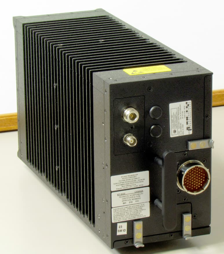
FRWRT-5000P-03
Dec 28, 201229.7 to 960 MHz Tactical Airborne Transceiver
Equipment Class
TNB - Licensed Non-Broadcast Station Transmitter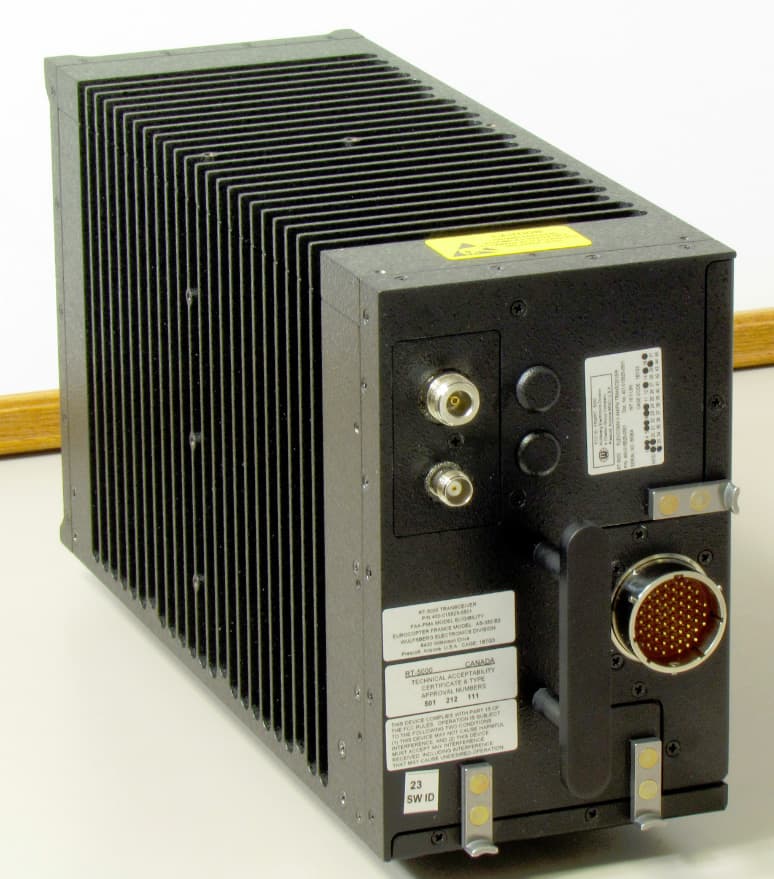
FRWRT-5000P-06
Dec 28, 201229.7 to 960 MHz Tactical Airborne Transceiver
Equipment Class
TNB - Licensed Non-Broadcast Station Transmitter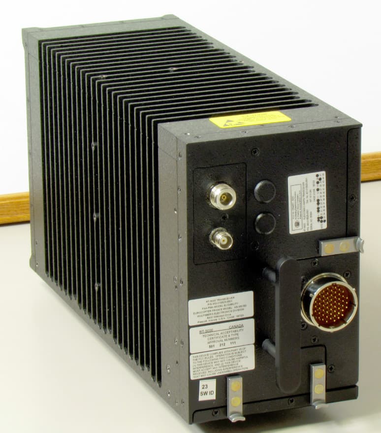
FRWRT-5000P-04
Dec 28, 201229.7 to 960 MHz Tactical Airborne Transceiver
Equipment Class
TNB - Licensed Non-Broadcast Station Transmitter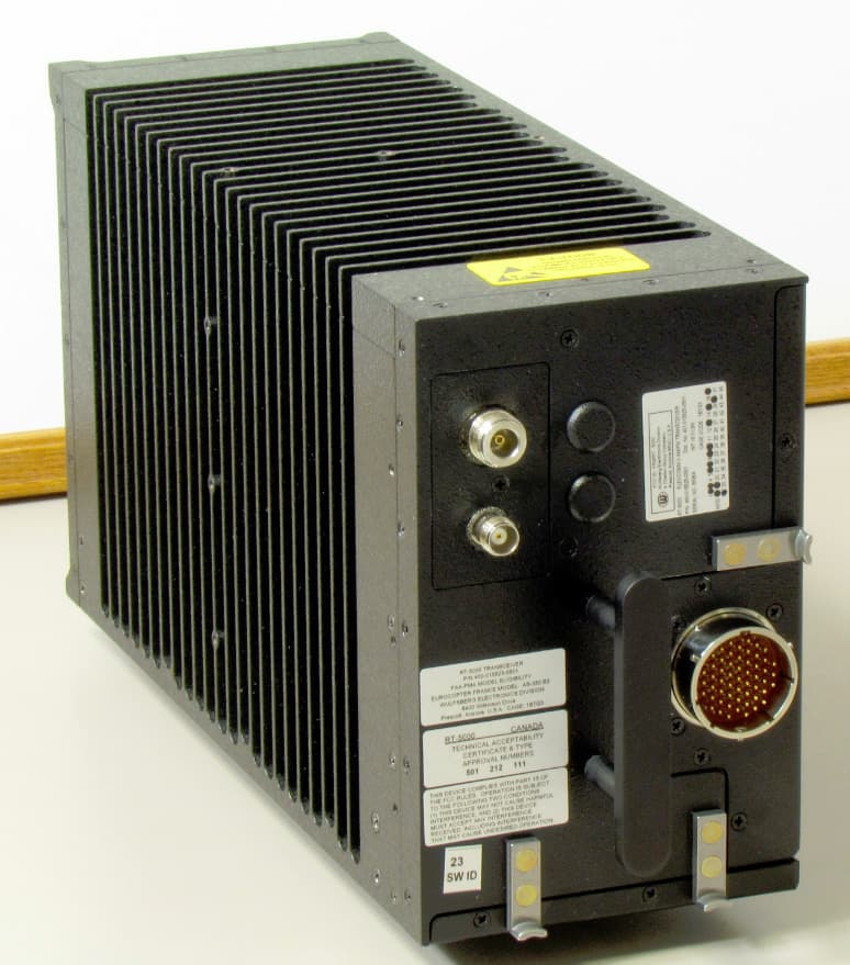
FRWRT-5000P-05
Dec 28, 201229.7 to 960 MHz Tactical Airborne Transceiver
Equipment Class
TNB - Licensed Non-Broadcast Station Transmitter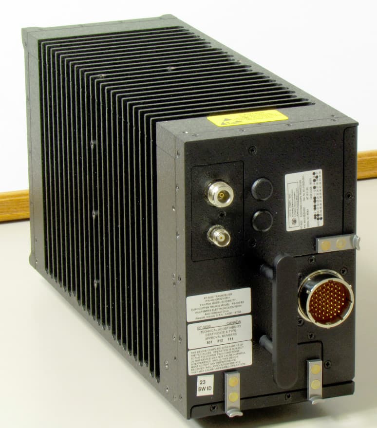
FRWRT-5000P-08
Dec 27, 201229.7 to 960 MHz Tactical Airborne Transceiver
Equipment Class
TNB - Licensed Non-Broadcast Station Transmitter