FSUGG0007GAME PAD
KYE SYSTEMS CORP.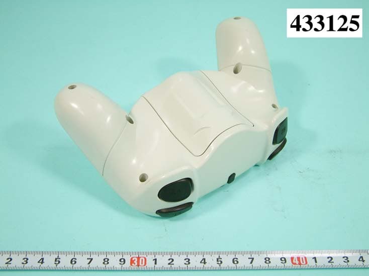
Click to zoom
Application Details
- Equipment Class
- DXX - Part 15 Low Power Communication Device Transmitter
- Date of Grant
- Jul 06, 2004
- Application Purpose
- Original Equipment
- Date of Application
- Jul 06, 2004
- Equipment Note
- GAME PAD
- Frequency Range
- 2402.00000000 - 2480.00000000
- Company
- KYE SYSTEMS CORP.
- Country
- Taiwan
Documents & Files
Document Text
Text extracted from the exhibit documents filed with the FCC. Open a document above to read the original.
Users Manual
FEDERAL COMMUNICATIONS COMMISSION This device complies with Part 15 of the FCC Rules. Operation is subject to the following two conditions:(1) this device may not cause harmful interference, and (2) this device must accept any interference received, including interference that may cause undesired operation. Changes or modifications not expressly approved by the party responsible for compliance could void the user‘s authority to operate the equipment. NOTE This equipment has been tested and found to comply with the limits for a Class B digital device, pursuant to Part 15 of the FCC Rules. These limits are designed to provide reasonable protection against harmful interference in a residential installation. This equipment generates, uses and can radiated radio frequency energy and, if not installed and used in accordance with the instructions, may cause harmful interference to radio communications. However, there is no guarantee that interference will not occur in a particular installation If this equipment does cause harmful interference to radio or television reception, which can be determined by turning the equipment off and on, the user is encouraged to try to correct the interference by one or more of the following measures: -Reorient or relocate the receiving antenna. -Increase the separation between the equipment and receiver. -Connect the equipment into an outlet on a circuit different from that to which the receiver is connected. -Consult the dealer or an experienced radio/TV technician for help. This device and its antenna(s) used for this transmitter must not be co-located or operating in conjunction with any other antenna or transmitter. This equipment complies with FCC radiation exposure limits set forth for an uncontrolled environment. Instruction Manual Thank you for purchasing this product. Before using this product, carefully read this manual to ensure proper and safe use of this product. For details, refer to the PlayStation ® 2 console’s instruction manual. This cordless analog controller can be used only with the PlayStation ® 2 computer entertainment system. Using the cordless analog controller ● You can switch between digital and analog modes. — PlayStation ® 2 format software can be operate in analog mode with the following control buttons: left analog stick / right analog sticks; △,○,Χ,□ buttons; directional button; L1, L2, R1, R2 buttons. The ultra-sensitive analog buttons from this cordless analog controller can be used with PlaySation ® 2 console. When the controller is in analog mode, buttons and sticks may operate in analog fashion depending on the features supported by the software title. Refer to the software manual for details. — The corresponding analog mode can be used in PlayStation ® 2 format software. When in analog mode, you can enjoy the analog operation of the left analog stick and right analog stick. This function is only available for software supporting the corresponding analog mode. ● When in the analog mode, you can enjoy the vibration function and unique gaming experience. ※ For details, refer to the software manual. Description of Cordless Game Controller * The R3 button and the L3 button function when the stick is pressed. * When the indicator turns red and LED flashes (low battery), connect the DC cable from the receiver unit to the DC IN connector- of the cordless analog controller to avoid the hassle of replacing the batteries during your game play. SELECT button L1 button / L2 button Directional button POWER button / LED mode indicator Right-analog stick / R3 button *DC IN outlet START button □ button R1 button / R2 button △ button ○ button X button Left-analog stick / L3 butto n ANALOG mode button *DC IN outlet LED indicator / ID button Receiver unit connector How to install 1. Turn OFF the PlayStation ® 2 console. 2. Insert batteries into the coreless analog controller paying attention to the plus and minus ends as indicated in the battery compartment. 3. Insert the receiver unit connector securely into the controller port (Console port 1 and Port 2) located on the front panel of the PlayStation ® 2 console. 4. Turn ONPlayStation ® 2 console. 5. When using it for the first time, press and hold the button on the receiver unit for two seconds and release till the receiver unit LED lights up in ORANGE. 6. Press the POWER button on the cordless analog controller. The mode indicator LED located on the cordless analog controller will light up in ORANGE and start connecting with receiver unit. 7. After the cordless analog controller connects to the receiver unit, the receiver unit indicator LED will turn to GREEN from ORANGE and the mode indicator of the cordless analog controller will go off (the mode indicator indicates the mode status at present). 8. Once the connection is completed, you can use the controller right away without setting it again. Please repeat the above steps if the connection fails or there is any interruption that occurred during operation. Before using the cordless analog controller, rotate the analog sticks once with your thumbs as shown in the diagram above. Please make sure all steps are properly followed. Mode switching and the mode indicator ANALOG mode button Mode Indicator The cordless analog controller can be switched between two modes by pressing the ANALOG mode button. Each time the ANALOG mode button is pressed, the mode changes as follows: Digital mode (indicator: GREEN lights up for one second before going off.) Analog mode (indicator: RED lights up for one second before going off.) ※ After confirming the software, switch to the appropriate mode. Note that some software makes this adjustment automatically. In such cases, the software overrides the ANALOG mode button. Vibration function The cordless analog controller features a vibration function. For details, refer to software manual and software option screen. ※ The vibration function will automatically stop when the battery level is low and the red LED indi…
Text truncated - open the document above for the full version.
Cover Letter(s)
KYE SYSTEMS CORP. No. 492, Sec. 5, Chung Hsin Rd., San Chung, Taipei Hsien, 241, Taiwan, R.O.C. Tel: 866-2-29956645 Fax: 866-2 -29956649 Federal Communications Commission Authorization and Evaluation Division Confidentiality Request regarding application for certification of FCC ID: (FSUGG0007 and FSUGG0008). Pursuant to Sections 0.457 and 0.459 of the Commission’s Rules, we hereby request confidential treatment of information accompanying this application as outlined below: Block Diagrams Schematic The above materials contain trade secrets and proprietary information not customarily released to the public. The public disclosure of these materials may be harmful to the applicant and provide unjustified benefits to its competitors. The applicant understands that pursuant to Section 0.457 of the Rules, disclosure of this application and all accompanying documentation will not be made before the date of the Grant for this application. Sincerely, (signature) Scotte Tsou (printed name)
External Photos
APPENDIX A. Photographs of EUT
Operational Description
FCC ID:FSUGG0007 Description of Operation EUT is a Wireless Game Controller with 79 channels. This device provided of transmitting speed 250Kbps . The device of RF carrier is GFSK. The device adapts Frequency Hopping Spread Spectrum modulation ( FHSS ). The antenna is Printed Antenna, and there is no antenna connector. This controller is compatible with any game including PS2 software, that supports digital control, analog control, vibration function and/or pressure sensitive function. The controller used for basic game play on PS2 game console.
Test Report
FCC ID: FSUGG0007 Issued on Jun. 11, 2004 Report No.: F433125 SPORTON International Inc. TEL : 886-2-2696-2468 FAX : 886-2-2696-2255 FCC TEST REPORT CATEGORY : Portable End Product PRODUCT NAME : Game Pad FCC ID. : FSUGG0007 FILING TYPE : Certification MODEL NAME : OG-03002 BRAND NAME : KYE APPLICANT : KYE SYSTEMS CORP No. 492, Sec. 5, Chung Hsin Rd., San Chung, Taipei Hsien, 241, Taiwan, R.O.C. MANUFACTURER : Same as Applicant ISSUED BY : SPORTON INTERNATIONAL INC. 6F, No. 106, Sec. 1, Hsin Tai Wu Rd., His Chih, Taipei Hsien, Taiwan, R.O.C. Statements: The test result in this report refers exclusively to the presented test model / sample. Without written approval of SPORTON International Inc., the test report shall not be reproduced except in full. Certificate or Test Report could not be used by the applicant to claim the product endorsement by CNLA, NVLAP or any agency of U.S. government. The test equipment used to perform the test are calibrated and traceable to NML/ROC or NIST/USA. Dr. Alan Lane Vice General Manager Sporton International Inc. Lab Code: 200079-0 FCC ID: FSUGG0007 Issued on Jun. 11, 2004 Report No.: F433125 SPORTON International Inc. FCC ID. : FSUGG0007 TEL : 886-2-2696-2468 Page No. : i FAX : 886-2-2696-2255 Issued Date : Jun. 11, 2004 Table of Contents History of this test report..................................................................................................................ii 1. General Description of Equipment under Test.............................................................................................1 1.1 Applicant ...........................................................................................................................................................1 1.2 Manufacturer.....................................................................................................................................................................................1 1.3 Basic Description of Equipment under Test......................................................................................................................................1 1.4 Features of Equipment under Test ...................................................................................................................................................1 2. Test Configuration of the Equipment under Test.........................................................................................2 2.1 Description of the Test ......................................................................................................................................................................2 2.1 Frequency Range Investigated .........................................................................................................................................................2 2.2 Description of Test Supporting Units ................................................................................................................................................2 2.3 Connection Diagram of Test System ................................................................................................................................................3 3. Test Location and Standards .........................................................................................................................4 3.1 Test Location ....................................................................................................................................................................................4 3.2 Test Conditions .................................................................................................................................................................................4 3.3 Standards for Methods of Measurement...........................................................................................................................................4 3.4 DoC Statement .................................................................................................................................................................................4 4. List of Measurements......................................................................................................................................5 4.1 Summary of the Test Results............................................................................................................................................................5 5. Test Result .......................................................................................................................................................6 5.1 Carrier Field Strength........................................................................................................................................... 6 5.2 AC Powerline Conducted Emission.........................................................................................................................11 5.3 Test of Radiated Emission.....................................................................................................................................14 6 Antenna Requirements .................................................................................................................................32 7 List of Measuring Equipments Used ...........................................................................................................33 Appendix A. Photographs of EUT.......................................................................................................... A1 ~ A6 FCC ID: FSUGG0007 Issued on Jun. 11, 2004 Report No.: F433125 SPORTON International Inc. FCC ID. : FSUGG0007 TEL : 886-2-2696-2468 Page No. : ii FAX : 886-2-2696-2255 Issued Date : Jun. 11, 2004 History of this test report ■ No additional attachment. □ Additional attachment were issued as following record: Attachment No. Issue Date Description FCC ID: FSUGG0007 Issued on Jun. 11, 2004 Report No.: F433…
Text truncated - open the document above for the full version.
Contact Information
Applicant
Ricky Chen(Section Supervisor)
Test Firm
SPORTON International IncKathy Lin
Technical Specifications
| # | Rule Parts | Frequency Range | Power Output |
|---|---|---|---|
| 1 | 15C | 2.40 GHz - 2.48 GHz | - |
Other Applications from KYE SYSTEMS CORP.
FSUGG0AM
Aug 20, 2026Wireless Speaker
Equipment Class
DSS - Part 15 Spread Spectrum Transmitter
FSUGKZI2
May 23, 2026Wireless Keyboard
Equipment Class
DXX - Part 15 Low Power Communication Device TransmitterFSUGMZN6
Apr 20, 2026Wireless Mouse
Equipment Class
DTS - Digital Transmission SystemFSUGMZN4
Apr 03, 2026Wireless Mouse
Equipment Class
DXX - Part 15 Low Power Communication Device TransmitterFSUGMZN7
Apr 01, 2026Wireless Mouse
Equipment Class
DTS - Digital Transmission System