FSUGG000A2.4GHz PS2 GAME PAD
KYE SYSTEMS CORP.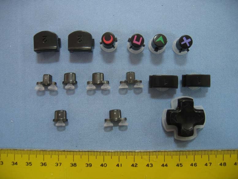
Click to zoom
Application Details
- Equipment Class
- DTS - Digital Transmission System
- Date of Grant
- Feb 23, 2006
- Application Purpose
- Original Equipment
- Date of Application
- Feb 23, 2006
- Equipment Note
- 2.4GHz PS2 GAME PAD
- Frequency Range
- 2402.00000000 - 2481.00000000
- Company
- KYE SYSTEMS CORP.
- Country
- Taiwan
Documents & Files
Document Text
Text extracted from the exhibit documents filed with the FCC. Open a document above to read the original.
Users Manual
Wireless PS2 Controller FEATURE This Wireless controller uses state of the art technology for a better gaming experience. The technology used in this controller al lows up to 16 pl ayers to use these controllers in one area. The ergonomically designed grips combine functionality as well as comfort. The use of 2 AA batteries(not included)allows for up to 70 hours of pl ay time depending on the use of the vibration control switch. In most cases the software used for game pl ay wil l di ctate the functions of the controller buttons. See 'Controller Setup' in the software game menu. Prior to using the controller, you should move the Analog Sticks in a circular motion. 1. State Of The Art2.4GHz Technology Allows Up To 16 Players 2. Ergonomic Analog Sticks & Directional Pad For Superior Control 3. Uses 2 AA Batteries(Not Included) For Up TO 70 Hours Of Play Time 4. Rubberized Grips For Comfortable Handling 5. Auto-Detect Feature For Simplified Set Up 6. Digital and Analog Modes 7.Turbo Function For Rapid Fire INSTRUCTION 1.Remove the battery cover on the back of the controller and insert 2AA batteries, Replace the cover. 2.Plug the receiver into one of the PS2 controller ports of PS2 console 3.If the LED on the receiver does not automatically begin flashing, press the connect button on the receiver. The red LED should now be flashing. This indicates that it is searching for a controller to connect to . 4.Turn the controller on using the on/off switch on the the controller. 5.If the LED on the controller is off or flashing, Press the connect button on the controller. If it automatically turns on ,proceed to next step. 6.The controller and receiver should be connected now. The red LED on the controller should be on ,and the red LED on the receiver should have stopped flashing and should be on .You are now ready to pl ay. Repeat the above procedure for each Plug only one receiver into the Ps2 console. Follow the procedure above for connecting that controller. Then pl ug the second receiver into the Ps2 console and follow the procedure above for connecting that controller. Continue connecting them one at a time until al l your controllers are connected. You may use up to 16 of these controllers in one area without interfering with each other. TURBO&CLEAR FUNCTIONS: Use the Turbo function for auto repeat(auto fire). When activated, this wil l cause the selected button to repeat its function until you release the button . TO SET AN ACTION BUTTON TO TURBO: Press and hold the TURBO button. Press and release any action buttons you want to put into Turbo mode. Release the TURBO button. TO CLEAR THE TURBO FUNCTION FROM AN ACTION BUTTON: Press and hold the Turbo button. Press and rel ease any action buttons you wish to clear. Release the Turbo button. The action buttons you pressed wil l now return to their original function. MODE BUTTON&LED INDICATOR: Use to change mode selection (di gi tal or analog). The LED indicator wil l il luminate in analog mode, and wil l not illuminate in digital mode. DIGITAL MODE: In this mode the controller acts li ke the origial Sony controller for PlayStation. The analog Sticks wil l fuction the same as the Directional Pad. The R3&L3 buttons are not active. ANALOG MODE: In this mode, you wil l have more accurate control over your movement. The following button wil l be active: Right&Left Analog Sticks, X, , , . Directional Pad&R1, R2, L1, L2. The R3&L3 analog Sticks are also functional. To activate, press down on them until you feel a click. LOW POWER: Battery power lower, the POWER LED is blinking. SLEEP MODE: Sleep Mode is smart feature for saving battery li fe. If the Controller is left alone without movement for 2 minutes, It enters sleep mode. If you want to continue play, press on any key. This feature allows player to save battery life if you forget to turn off the power switch. NOTE: You should always refer to the software in use for the suggested mode for play. In some instances, the software may automatically change to the correct mode and you may not be able to change this. The function of the buttons can change and/or be non-functional depending on the mode selected. TROUBLESHOOTING If you turn a controller off and on ,or unplug a receiver you may lose the connection between that controller and receiver. If you have lost the connection, unplug the receiver and turn off the controller. Pl ug the receiver in and press the connect button on the receiver. Turn the controller on, and if necessary, press the connect button on the controller. Whenever you are trying to connect a receiver and controller, unplug the receiver and turn off the controller and follow the steps outlined above in Setup for each controller. WARNING Read, follow & understand all w arnings in this manual, your video game system instruction manual & video software for safety, health & other information Do not submerge in water Do not disassemble any part of controller & receiver Do not place heavy objects on top of controller & receiver Do not allow small children to play with controller & receiver unsupervised Do not use this controller in any other way than its intended use Do not unplug controller cable whi le the console is turned on Keep away from areas where dirt or liquid can get into controller & receiver Keep away from extreme temperatures Store in areas away from dust and humidity Turn off or discontinue use of Vibration function if you have any hand or wrist ailments or if you have any injury's to which the vibration creates discomfort to you in any way L2 Button Analog Start Directional Pad ConnectMacro Turbo R Analog Power&Vibration Control Switch Stick L AnalogStick Power LED R2 Button R1 Button L1 Button Select Button Button Button Button Connect Button Connect LED Power LED MACRO&CLEAR FUNCTION: Use to macro and create a sequence of movements with the touch of one button. During game pl ay, pressing the macro button wil l activate our selected sequence. TO SET AN ACTION BUTTON TO M…
Text truncated - open the document above for the full version.
Block Diagram
Block diagram description 1. Transmitter block diagram The part is controlled mainly by MCU. Key Scan is used to detected the Keys of Gamepad, LED Display is used to indicated status of the Gamepad, MOTOR VIBRATION is used to report vibration message which come from the host, RF MODULE is used to transmit and receive RF signal, POWER MANOSTAT is used to regulate the power which is supplied by battery stably, and then output it to all circuit. The following is the principle: the MCU will encode KEY SCAN message then transmit it to RF MODULE as soon as it is detected by MCU, and then transmit it to receiver; then RF MODULE will receive vibration message of the motor and transmit it to MCU, after having decoded it, MCU will enable MOTOR VIBRATION Circuit, at same time, MCU will control the LED DISPLAY block to indicate the correspondent working status of the Gamepad. 2. Receiver block diagram The part also is controlled mainly by MCU, LED Display is used to indicate RF connection, RF MODULE is used to transmit and receive RF signal, POWER MANOSTAT is used to regulate the power which is supplied by PS2 CONSOLE stably, and then output it to all circuit. Attention, the receiver doesn’t include PS2 CONSOLE which is a necessary host for the receiver. The following is the principle: when RF MODULE have received the KEY SCAN message of Gamepad, it will transmit the message to MCU, MCU will decode the message, then the decoded message will be transmitted to PS2 CONSOLE. PS2 CONSOLE will transmit MOTOR VIBRATION message to MCU, the MCU will encode the message, then the encoded message will be transmitted to RF MODULE which will transmit it out at once. KEY SCAN block may control the RF connection via MCU. 1 2 3 4 ABCD 4 3 2 1 D CBA Manostat Power PS2 Console RF Module (Transceiver) MCU CodingDecode LED Display KeyScan RF ANT 1 2 3 4 ABCD 4 3 2 1 D CBA RF Module(Transceiver) MCU CodingDecodePower Manostat Key ScanLED Display Motor Vibration Battery RF ANT Transmitter block diagram
External Photos
Spectrum Research & Testing Lab., Inc. No. 101-10, Ling 8, Shan-Tong Li, Chung-Li City, Taoyuan, Taiwan, R.O.C. PHOTOS OF EUT Spectrum Research & Testing Lab., Inc. No. 101-10, Ling 8, Shan-Tong Li, Chung-Li City, Taoyuan, Taiwan, R.O.C. PHOTOS OF EUT Spectrum Research & Testing Lab., Inc. No. 101-10, Ling 8, Shan-Tong Li, Chung-Li City, Taoyuan, Taiwan, R.O.C. PHOTOS OF EUT Spectrum Research & Testing Lab., Inc. No. 101-10, Ling 8, Shan-Tong Li, Chung-Li City, Taoyuan, Taiwan, R.O.C. PHOTOS OF EUT
ID Label/Location Info
Spectrum Research & Testing Lab., Inc. No. 101-10, Ling 8, Shan-Tong Li, Chung-Li City, Taoyuan, Taiwan, R.O.C. Sample of FCC ID Label The device is large enough for it to be placed warning statement on the device as follow: FCC ID: FSUGG000A This device complies with Part 15 FCC Rules. Operation is subject to the following two conditions: (1) This device may not cause harmful interference. (2) This device must accept any interference received including interference that may cause undesired operation.
Internal Photos
Spectrum Research & Testing Lab., Inc. No. 101-10, Ling 8, Shan-Tong Li, Chung-Li City, Taoyuan, Taiwan, R.O.C. PHOTOS OF EUT Spectrum Research & Testing Lab., Inc. No. 101-10, Ling 8, Shan-Tong Li, Chung-Li City, Taoyuan, Taiwan, R.O.C. PHOTOS OF EUT Spectrum Research & Testing Lab., Inc. No. 101-10, Ling 8, Shan-Tong Li, Chung-Li City, Taoyuan, Taiwan, R.O.C. PHOTOS OF EUT
Operational Description
Spectrum Research & Testing Lab., Inc. No. 101-10, Ling 8, Shan-Tong Li, Chung-Li City, Taoyuan, Taiwan, R.O.C. Operational Description of equipment 2.4GHz PS2 GAME PAD FCC ID: FSUGG000A The wireless game pad inserted 2 AA batteries is operated under game system as PS2. It’s frequency band is from 2400 to 2481 MHz, amounting 20 channels under operation. The operation is stated clearly as follow: (1) Puts the dongle part into the game system’s pad slot, then turns on the game system. (2) Press the connect button of the dongle. At the same time, the LED is going to flash. (3) Press the game pad’s connect button, it will flash too. When the LED sustain light at both game pad and dongle. The game pad can be used to control the game system. PRODUCT 2.4G PS 2 GAME PAD MODEL NO. Wireless Blaze ( PS2 ) POWER SUPPLY DC 3V 10m FREQUENCY BAND 2400~2481HMz NUMBER OF CHANNEL 20 RATED RF OUTPUT POWER 0dBm MODULATION TYPE FSK BIT RATE OF TRANSMISSION 1Mbps ANTENNA TYPE Integral Antenna
Schematics
1 2 34 ABCD 4 3 2 1 D CBA Title Number Revision Size A4 Date: 30-Aug-2005 Sheet of File: F:\HONG\ps joyspad.ddb Drawn By: +7.5V +3.3VD GND ACKDODICLKCS BC30.1UF PSX PLUG FRONT VIEW CN1 357 1 9264 ACKCLKCS+3.5VGND+7.5VDODI CONNECTION L11.8 Ω LINK R11M BC133P BC233P Y124MHZ 尽量靠近 IC +3.3VD +3.3VD RF12MBDDATA1BDPWRBDCLKBDDATABNDENBPKTCTLBXTLEN RX PW R41K ACK 1 CLK 2 CS 3 DO 4 DI 5 SELA1 6 SELA2 7 SELA3 8 SELA4 9 RFADA1 10 RFADA2 11 RFADA3 12 RFADA4 13 RFADA5 14 RFADA6 15 RFADA7 16 AUTOPAD 17 DIS3D 18 RFSET 19 RFLED 20 GND 21 XTAL1 22 XTAL2 23 VDD 24 RF12M 25 BDDATA1 26 BDPWR 27 BDCLK 28 BDDATA 29 BNDEN 30 BXTLEN 31 BPKTCTL 32 YR8450-927 U1YR8450-127A ACKCLKCSDODI 123456789 PSJK R34.7K R24.7K +3.3VD YR8450-127A EC1 220UF/10V BPKTCTLBXTLENBNDENBDDATABDCLKBDPWRBDDATA1RF12M BC4C104 +3.3VD 电容尽量靠近模 1234567891011 RFSIGNIA MODULE 旭邦科技 AK42-RF PSII RX (2038) SCH V1.0 1 2 3 4 56 ABCD 6 5 4 3 2 1 D CBA Title Number Revision Size B Date: 30-Aug-2005 Sheet of File: F:\HONG\ps joyspad.ddb Drawn By: CONNECT SELECTSTART RFLED TURLED R56.8M BC533PBC433P Y1 24MHZ BC3104P EC2 100UF/10V EC447UF/16V Power EC1 100UF/10V +3.0VD ANALOG LED RF12M BADATA1 BNPWR BDCLK BDDATA RFCSRFCEBPKTCTL BPKTCLBXTLENBNDENBDDATABDCLKBNPWRBADATA1RF12M LMOTORRMOTOR RMOTOR Q38050 Q28050 R1330R R310K BC2 104P VC1 D21N4148 VC1 Q48050 Q18050 R2330R R410K BC1104P LMOTOR VC1 D1 1N4148 VC1 RP1RP2RP3RP4 BD BR BU POWERCHECK POWERCHECK R1 R2 L1 L2 AU AR +3.0V +3.0VD L2 25k L1 25K L2L1UPLEFTRIGHTDOWNR2R1BUBR BL BD R19 10K R17 10KR16 10KR18 10KR9 10KR8 10KR20 10KR23 10KR22 10KR6 10KR7 10K R21 10K BU 25K BL 25K R1 25K R2 25K BL AD AL +3.0VD MG1 MG2 MACRO +3.3VD ANALOG +3.0VD MACRO LED GPLED TURBO BR 25KBD 25K L2R2 BUBLBRBDR1L1 AL 25K AR 25KAU 25KAD 25K AUARADAL ANALOG SELECT START L3 R3 STARTSELECTANALOG AUTOPAD +3.0VD 1234567891011 RF SIGNIA MODULE VC1 AL 1 GND 2 XTAL1 3 XTAL2 4 VDD 5 DISRL 6 RFFRE1 7 RFFRE2 8 RFFRE3 9 RFFRE4 10 RFADD1 11 RFADD2 12 RFADD3 13 RFADD4 14 RFADD5 15 RFADD6 16 RFADD7 17 RFSEL 18 CONNECT 19 MODE1 20 OPTION 21 OPTION1 22 OPTION2 23 RFLED 24 RPLED 25 GPLED 26 MOTORLED 31 TURLED 27 SLOWLED 28 PROGRAMLED 29 ANALOGLED 30 RF12M 32 BDDATA1 33 RFPWR 34 RFDATA 35 RFCLK 36 RFDR 37 BDDATA 38 RFCS 39 RFCE 40 BPKTCTL 41 LMOTOR 42 RMOTOR 43 PROGRAM 46 KEY-TURBO 47 KEY-CLR 48 KEY-SLOW 49 Q 50 D 51 C 52 S 53 RP1 54 RP2 55 RP3 56 RP4 57 BD 58 BR 59 BL 60 BU 61 POWERCHECK 62 R1 63 L1 64 R2 65 L2 66 R3 67 L3 68 START 69 SELECT 70 AUTOPAD 71 ANALOG 72 AU 73 AR 74 AD 75 YR8450-917C MOTORKEY 44 POWERKEY 45 U1YR8450-117C L/R U/D R3DVR-3D L/R U/D L3D VR-3D RP1 RP2 RP3 RP4 L3 R3 +3.0VD 1 234 SW-M +3.0VD R1112K R105.1K R131.8K R151.8K R121.8K R141.8K 12345678910 P2BCON10 1234567891011 P1BHEADER 11 ANALOGLED ANALOGLED TURLED TURLED GPLED GPLED RFLED RFLED MACROLED MACROLED CONNECT CONNECTAUARADAL+3.3VD PROGRAM PROGRAM TURBO TURBOBDBRBLBUSTARTSELECTANALOGGND +3.0VD YR8450-117C 旭邦科技 AK42-RF PSII TX (2038) SCH V1.0
Test Report
Spectrum Research & Testing Lab., Inc. No. 101-10, Ling 8, Shan-Tong Li, Chung-Li City, Taoyuan, Taiwan TEST REPORT Reference No.: A05101405 Report No.: FCCA05101405 FCCID: FSUGG000A Page:2 of 54 Date:Jan. 02, 2006 TABLE OF CONTENTS 1. DOCUMENT POLICY AND TEST STATEMENT....................................................4 1.1 DOCUMENT POLICY......................................................................................... 4 1.2 TEST STATEMENT ............................................................................................ 4 1.3 EUT MODIFICATION...........................................................................................4 2. DESCRIPTION OF EUT AND TEST MODE................................................. 5 2.1 GENERAL DESCRIPTION OF EUT ................................................................... 5 2.2 DESCRIPTION OF SUPPORT UNIT.................................................................. 5 2.3 DESCRIPTION OF TEST MODE ....................................................................... 6 3. DESCRIPTION OF APPLIED STANDARDS................................................ 6 4. CONDUCTED EMISSION TEST .........................................................................7 4.1.1 CONDUCTED EMISSION LIMIT ..................................................................... 7 4.1.2 TEST EQUIPMENT ......................................................................................... 7 4.1.3 TEST SETUP .................................................................................................. 8 4.1.4 TEST PROCEDURE ....................................................................................... 8 4.1.5 EUT OPERATING CONDITION ...................................................................... 8 4.1.6 TEST RESULT ................................................................................................ 9 4.2 TECHNICAL CHARACTERISTICS TEST.................................................. 13 4.2.1 6dB Bandwidth .............................................................................................. 13 4.2.2 LIMIT ............................................................................................................. 13 4.2.3 TEST EQUIPMENT ....................................................................................... 13 4.2.4 TEST SET-UP ............................................................................................... 13 4..2.4 TEST PROCEDURE .................................................................................... 13 4.2.5 EUT OPERATING CONDITION .................................................................... 13 4.2.6 TEST RESULT .............................................................................................. 14 4.3 PEAK POWER TEST ....................................................................................... 18 4.3.1 LIMIT ................................................................................................................ 18 4.3.2 TEST EQUIPMENT ....................................................................................... 18 4.3.3 TEST SET-UP ............................................................................................... 19 4.3.4 TEST PROCEDURE ..................................................................................... 19 4.3.5 EUT OPERATING CONDITION .................................................................... 19 4.3.6 TEST RESULT .............................................................................................. 19 4.4 BAND EDGE TEST .......................................................................................... 24 4.4.1 LIMIT ................................................................................................................ 24 4.4.2 TEST EQUIPMENT ....................................................................................... 25 4.4.3 TEST SET-UP ............................................................................................... 26 4.4.4 TEST PROCEDURE ..................................................................................... 27 4.4.5 EUT OPERATING CONDITION .................................................................... 27 4.4.6 TEST RESULT .............................................................................................. 28 4.5 FUNDERMENTAL & SPURIOUS RADIATED EMISSION TEST ...................... 32 4.5.1 LIMIT................................................................................................................ 32 Spectrum Research & Testing Lab., Inc. No. 101-10, Ling 8, Shan-Tong Li, Chung-Li City, Taoyuan, Taiwan TEST REPORT Reference No.: A05101405 Report No.: FCCA05101405 FCCID: FSUGG000A Page:3 of 54 Date:Jan. 02, 2006 4.5.2 TEST EQUIPMENT ....................................................................................... 33 4.5.3 TEST SET-UP ............................................................................................... 34 4.5.4 TEST PROCEDURE ..................................................................................... 35 4.5.5 EUT OPERATING CONDITION .................................................................... 35 4.5.6 TEST RESULT .............................................................................................. 36 4.7 POWER DENSITY TEST................................................................................ 43 4.7.1 LIMIT ................................................................................................................ 43 4.7.2 TEST EQUIPMENT.......................................................................................... 43 4.7.3 TEST SET-UP .................................................................................................. 43 4.7.4 TEST PROCEDURE ........................................................................................ 43 4.7.5 EUT OPERATING CONDITION .........................…
Text truncated - open the document above for the full version.
Test Setup Photos
Spectrum Research & Testing Lab., Inc. No. 101-10, Ling 8, Shan-Tong Li, Chung-Li City, Taoyuan, Taiwan TEST REPORT Reference No.: A05101405 Report No.: FCCA05101405 FCCID: FSUGG000A Page:49 of 54 Date:Jan. 02, 2006 6. PHOTOS OF TESTING - Conducted test Spectrum Research & Testing Lab., Inc. No. 101-10, Ling 8, Shan-Tong Li, Chung-Li City, Taoyuan, Taiwan TEST REPORT Reference No.: A05101405 Report No.: FCCA05101405 FCCID: FSUGG000A Page:50 of 54 Date:Jan. 02, 2006 - Conducted test Spectrum Research & Testing Lab., Inc. No. 101-10, Ling 8, Shan-Tong Li, Chung-Li City, Taoyuan, Taiwan TEST REPORT Reference No.: A05101405 Report No.: FCCA05101405 FCCID: FSUGG000A Page:51 of 54 Date:Jan. 02, 2006 - Radiated test (Link) Spectrum Research & Testing Lab., Inc. No. 101-10, Ling 8, Shan-Tong Li, Chung-Li City, Taoyuan, Taiwan TEST REPORT Reference No.: A05101405 Report No.: FCCA05101405 FCCID: FSUGG000A Page:52 of 54 Date:Jan. 02, 2006 - Radiated test (TX) Spectrum Research & Testing Lab., Inc. No. 101-10, Ling 8, Shan-Tong Li, Chung-Li City, Taoyuan, Taiwan TEST REPORT Reference No.: A05101405 Report No.: FCCA05101405 FCCID: FSUGG000A Page:53 of 54 Date:Jan. 02, 2006 - Radiated test (TX)
Contact Information
Applicant
Ricky Chen(Section Supervisor)
Test Firm
Spectrum Research & Testing Laboratory, Inc.Cheng Ho
Technical Specifications
| # | Rule Parts | Frequency Range | Power Output |
|---|---|---|---|
| 1 | 15C | 2.40 GHz - 2.48 GHz | 400.00 µW |
Other Applications from KYE SYSTEMS CORP.
FSUGG0AM
Aug 20, 2026Wireless Speaker
Equipment Class
DSS - Part 15 Spread Spectrum Transmitter
FSUGKZI2
May 23, 2026Wireless Keyboard
Equipment Class
DXX - Part 15 Low Power Communication Device TransmitterFSUGMZN6
Apr 20, 2026Wireless Mouse
Equipment Class
DTS - Digital Transmission SystemFSUGMZN4
Apr 03, 2026Wireless Mouse
Equipment Class
DXX - Part 15 Low Power Communication Device TransmitterFSUGMZN7
Apr 01, 2026Wireless Mouse
Equipment Class
DTS - Digital Transmission System