FSUGMPAD
KYE SYSTEMS CORP.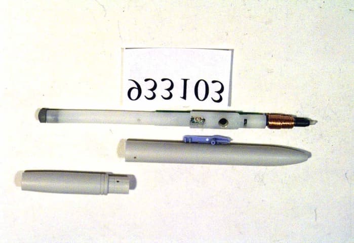
Click to zoom
Application Details
- Equipment Class
- JBP - Part 15 Class B Computing Device Peripheral
- Date of Grant
- Sep 27, 2000
- Application Purpose
- Original Equipment
- Date of Application
- Jun 24, 2000
- Company
- KYE SYSTEMS CORP.
- Country
- Taiwan
Documents & Files
Document Text
Text extracted from the exhibit documents filed with the FCC. Open a document above to read the original.
Users Manual
KYE SYSTEMS CORP. Equipment : Tablet Model : PowerMate Wireless FCC ID : FSUGMPAD
Users Manual
CyberScroll Wireless New Generation PC Input System KYE SYSTEMS CORP TEL: 886-2-2995-6645 FAX:886-2-29950414 WEBSITE: [email protected] The Genius CyberScroll Wireless is a powerful integrated graphic system that includes a cordless no-ball mouse, a graphic tablet and a cordless pen. Forget about a traditional mouse with a ball, the Genius precision no-ball mouse never needs cleaning and eliminates cable tangles. With Roller Patent No. 5530455, it supports Internet and Windows browsing instantly, and includes added-value software for assigning mouse buttons to your favorite keyboard shortcuts. With the extra value cordless pen and “PenSoft” & MGI “PhotoSuite" software that let you draw, sketch, add a note to an email, or simply sign your name on a document (E-paper functions), you can accomplish your ideas easily. Features: ! Cordless no-ball mouse and pen eliminates cord tangles, and dust accumulation ! Easier to move the cursor, draw, trace, paint, or add your signature to documents ! Supports the white board function on Internet NetMeeting ! Scroll through Windows and the Internet without using the scrollbars ! Customizable buttons for frequently-used program shortcuts ! Includes a pen stand, and transparency overlay for easy tracing ! Includes MGI PhotoSuite ima ge editing and Pensoft handwriting recognition software ! Supports Windows, 98, 95, and NT4.0 SPECIFICATIONS: ! Tablet Working Area: 5” x 4” ! Dimension: 230 x 189 x 7.5 mm ! Resolution: 1000 LPI ! Accuracy: ± 0.01inch SYSTEM REQUIREMENTS: ! IBM PC compatible, with Pentium 133 or higher ! PS/2 port ! Windows 95/98/NT ! CD-ROM drive PACKAGE CONTENTS: ! CyberScroll Wireless tablet ! Cordless Pen and pen stand ! Cordless Mouse ! Quick installation guide ! GeniTAB CD for software installation ! Transparent overlay SHIPPING INFORMATION ! PCs/CTN x CUFT”: 10 PCs/CTN x 2.28” ! CTN size: 510 x 416 x 305 mm ! 20-foot container: 3850 PCs ! 40-foot container: 7700 PCs Available date:
Users Manual
CyberScroll Wireless New Generation PC Input System KYE SYSTEMS CORP TEL: 886-2-2995-6645 FAX:886-2-29950414 WEBSITE: [email protected]
Users Manual
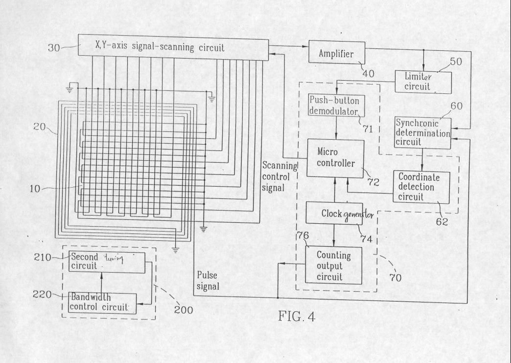
Cyber Scroll Tablet working theory : Fig 4 is a function block diagram of Cyber Scroll Tablet. Function Block description : 1. The micro-controller (72) generates control signal to each portion . For example, It enables the X-Y-axis scanning circuit (30), control the drive signal on/off, and read button status from push Button demodulator (71),then send coordinate position to PC via PSII interface. 2. Clock generator (74) generates system clock to micro-controller (72) , and provides Clock to counting output circuit(76) to generates a sinusoidal signal of 345.6KHz , the Counting output circuit drives the coil (20) to generates magnetic flux for PEN (200) ( or mouse PUCK) device energy. 3. The PEN (and mouse PUCK) device(200) didn’t have power inside , it will induce the power from Cyber Scroll tablet while application. 4. X-Y axis signal-scanning circuit (30) bypass the PEN ( or mouse PUCK ) feedback signal . But how did they work together ? Normally the micro-controller(72) enable the counting output circuit(76) to drive the coil(20) to generate magnetic flux and control the X-Y axis signal scanning circuit (30) to scan antenna area . It will get the energy by magnetic flux and feedback to antenna area (10). when PEN( or mouse PUCK(200)) is applied on the tablet surface , The X-Y axis signal scanninng circuit(30) which is composed of analog mutiplxer And it is connect to amplifier circuit (40) , the scanning circuit bypass the magnetic flux signal feedback from PEN(or mouse PUCK) to amplifier circuit(40). The amplifier circuit (40) will send out the magnetic flux signal by two ways, One is a limiting circuit (50),the other one is synchronic determination circuit (60). The limiting circuit (50) restricts the signal amplitude and provides the limited signal to push-button demodulator (71) to detect which button is pressed on PEN( or mouse PUCK). The magnetic flux signal and noise signal is mixed together . Synchronous determination circuit (60) is extracted the magnetic flux signal and send it to coordinate detection circuit (62). Micro-controller (72) will detect the coordinate and button status from coordinate Detection circuit (62) output signal and push-button demodulator circuit (71) output signal. Then micro-controller (72) process these signal ( coordinate signal and button Status signal ) and send to PC via PSII interface . End of these states micro-controller (72) will rescan the X-Y axis antenna Area and wait the PEN ( or mouse PUCK ) feedback signal for next cycle .
External Photos
FCC ID : FSUGMPADFRONT SIDE OF EUT Number 1 933103-01.JPG FCC ID : FSUGMPADREAR SIDE OF EUT Number 2 933103-02f1.JPG FCC ID : FSUGMPADMechanical Construction Number 3 933103-03.JPG FCC ID : FSUGMPADMechanical Construction Number 4 933103-04.JPG FCC ID : FSUGMPADMechanical Construction Number 5 933103-05.JPG FCC ID : FSUGMPADFront side of main board Number 6 933103-06.JPG FCC ID : FSUGMPADRear side of main board Number 7 933103-07.JPG FCC ID : FSUGMPADMechanical Construction (Mouse) Number 8 933103-08.JPG FCC ID : FSUGMPADMechanical Construction (Mouse) Number 9 933103-09.JPG FCC ID : FSUGMPADFront side of main board (Mouse) Number 10 933103-10.JPG FCC ID : FSUGMPADRear side of main board (Mouse) Number 11 933103-11.JPG FCC ID : FSUGMPADMechanical Construction (Mouse) Number 12 933103-12.JPG FCC ID : FSUGMPADMechanical Construction (Mouse) Number 13 933103-13.JPG FCC ID : FSUGMPADFront side of main board (Mouse) Number 14 933103-14.JPG FCC ID : FSUGMPADRear side of main board (Mouse) Number 15 933103-15.JPG
ID Label/Location Info
FCC ID LABEL LOCATION
ID Label/Location Info
FCC ID LABEL LOCATION FCC ID LABEL LOCATION LOCATION
Test Report
FCC TEST REPORT Report No. : F933103-2 SPORTON International Inc. FCC ID: FSUGMPAD TEL : 886-2-2696-2468Page No.: 1 of 27 FAX : 886-2-2696-2255Issued Date : Jun. 15, 1999 FCC TEST REPORT for CISPR PUB. 22 Class B Equipment: P08 Mouse Model No.: P08 Mouse for Cyberscroll wireless FCC ID: FSUGMPAD Filing Type: Original Grant Applicant: KYE SYSTEMS CORP. No. 492, Sec. 5, Chung Hsin Rd., San Chung, Taipei Hsien, 241, Taiwan, R.O.C. ! The test result refers exclusively to the test presented test model / sample. ! Without the written authorization of the test lab., the Test Report may not be copied. ! Certificate or Test Report must not be used by the applicant to claim the product in this test report endorsement by NVLAP or any agency of U.S. government. SPORTON International Inc. 6F, No.106, Sec. 1, Hsin Tai Wu Rd., Hsi Chih, Taipei Hsien, Taiwan, R.O.C. FCC TEST REPORT Report No. : F933103-2 SPORTON International Inc. FCC ID: FSUGMPAD TEL : 886-2-2696-2468Page No.: 2 of 27 FAX : 886-2-2696-2255Issued Date : Jun. 15, 1999 Table of Contents CERTIFICATE OF COMPLIANCE .............................................................................................................. 3 1. General Description of Equipment under Test..................................................................................... 4 1.1. Applicant .............................................................................................................................................................................................................. 4 1.2. Manufac turer ....................................................................................................................................................................................................... 4 1.3. Basic Description of Equipme nt under Test................................................................................................................................................... 4 1.4. Feature of Eq uipment under Tes t.................................................................................................................................................................... 4 2. Test Configuration of Equipment under Test....................................................................................... 5 2.1. Test Ma nner ........................................................................................................................................................................................................ 5 2.2. Description of Test S ystem............................................................................................................................................................................... 5 2.3. Connec tion Diagram o f Test Sys tem .............................................................................................................................................................. 7 3. Test Software ....................................................................................................................................... 8 4. General Information of Test ................................................................................................................. 9 4.1. Test Facility ......................................................................................................................................................................................................... 9 4.2. Standard for Methods o f Meas ure ment .......................................................................................................................................................... 9 4.3. Test in Comp liance with .................................................................................................................................................................................... 9 4.4. Freque nc y Range Investigated ........................................................................................................................................................................ 9 4.5. Test Distance ...................................................................................................................................................................................................... 9 5. Test of Conducted Powerline............................................................................................................. 10 5.1. Major Measuring Instrume nts .........................................................................................................................................................................10 5.2. Test Procedures ...............................................................................................................................................................................................11 5.3. Typical Test Setup La yo ut o f Co nduc ted Powerline ...................................................................................................................................12 5.4. Test Res ult o f AC Powerline Cond ucted Emission.....................................................................................................................................13 5.5. Photograp hs o f Cound ucted Powerline Tes t Configura tion ......................................................................................................................14 6. Test of Radiated Emission.................................................................................................................. 16 6.1. Major Measuring Instrume nts .........................................................................................................................................................................16 6.2. Test Procedures ...........................................................................................................................................................................................…
Text truncated - open the document above for the full version.
Test Report
FCC TEST REPORT Report No. : F933103-JBP SPORTON International Inc. FCC ID: FSUGMPAD TEL : 886-2-2696-2468Page No.: 1 of 27 FAX : 886-2-2696-2255Issued Date : Sep. 21, 2000 FCC TEST REPORT for CISPR PUB. 22 Class B Equipment: Tablet Model No.: PowerMate Wireless FCC ID: FSUGMPAD Filing Type: Original Grant Applicant: KYE SYSTEMS CORP. No. 492, Sec. 5, Chung Hsin Rd., San Chung, Taipei Hsien, 241, Taiwan, R.O.C. ! The test result refers exclusively to the test presented test model / sample. ! Without the written authorization of the test lab., the Test Report may not be copied. ! Certificate or Test Report must not be used by the applicant to claim the product in this test report endorsement by NVLAP or any agency of U.S. government. SPORTON International Inc. 6F, No.106, Sec. 1, Hsin Tai Wu Rd., Hsi Chih, Taipei Hsien, Taiwan, R.O.C. FCC TEST REPORT Report No. : F933103-JBP SPORTON International Inc. FCC ID: FSUGMPAD TEL : 886-2-2696-2468Page No.: 2 of 27 FAX : 886-2-2696-2255Issued Date : Sep. 21, 2000 Table of Contents CERTIFICATE OF COMPLIANCE .............................................................................................................. 3 1. General Description of Equipment under Test..................................................................................... 4 1.1. Applicant .............................................................................................................................................................................................................. 4 1.2. Manufac turer ....................................................................................................................................................................................................... 4 1.3. Basic Description of Equipme nt under Test................................................................................................................................................... 4 1.4. Feature of Eq uipment under Tes t.................................................................................................................................................................... 4 2. Test Configuration of Equipment under Test....................................................................................... 5 2.1. Test Ma nner ........................................................................................................................................................................................................ 5 2.2. Description of Test S ystem............................................................................................................................................................................... 5 2.3. Connec tion Diagram o f Test Sys tem .............................................................................................................................................................. 7 3. Test Software ....................................................................................................................................... 8 4. General Information of Test ................................................................................................................. 9 4.1. Test Facility ......................................................................................................................................................................................................... 9 4.2. Standard for Methods o f Meas ure ment .......................................................................................................................................................... 9 4.3. Test in Comp liance with .................................................................................................................................................................................... 9 4.4. Freque nc y Range Investigated ........................................................................................................................................................................ 9 4.5. Test Distance ...................................................................................................................................................................................................... 9 5. Test of Conducted Powerline............................................................................................................. 10 5.1. Major Measuring Instrume nts .........................................................................................................................................................................10 5.2. Test Procedures ...............................................................................................................................................................................................11 5.3. Typical Test Setup La yo ut o f Co nduc ted Powerline ...................................................................................................................................12 5.4. Test Res ult o f AC Powerline Cond ucted Emission.....................................................................................................................................13 5.5. Photograp hs o f Cound ucted Powerline Tes t Configura tion ......................................................................................................................15 6. Test of Radiated Emission.................................................................................................................. 19 6.1. Major Measuring Instrume nts .........................................................................................................................................................................19 6.2. Test Procedures ...............................................................................................................................................................................................20 6.3. Typ…
Text truncated - open the document above for the full version.
Contact Information
Applicant
Ricky Chen(Section Supervisor)
Technical Contact
SPORTON International Inc.Kathy Lin
[email protected]886-2-2696-2468
75-23 19St. Fresh Meadows · Taipei Hsien, New York · United States
Non-Technical Contact
SPORTON International Inc.Kathy Lin
[email protected]718-468-4260
Test Firm
Sporton International Inc.W. Huang
Technical Specifications
| # | Rule Parts | Frequency Range | Power Output |
|---|---|---|---|
| 1 | 15B | - | - |
Other Applications from KYE SYSTEMS CORP.
FSUGG0AM
Aug 20, 2026Wireless Speaker
Equipment Class
DSS - Part 15 Spread Spectrum Transmitter
FSUGKZI2
May 23, 2026Wireless Keyboard
Equipment Class
DXX - Part 15 Low Power Communication Device TransmitterFSUGMZN6
Apr 20, 2026Wireless Mouse
Equipment Class
DTS - Digital Transmission SystemFSUGMZN4
Apr 03, 2026Wireless Mouse
Equipment Class
DXX - Part 15 Low Power Communication Device TransmitterFSUGMZN7
Apr 01, 2026Wireless Mouse
Equipment Class
DTS - Digital Transmission System