FSUGMZH6WIRELESS MOUSE
KYE SYSTEMS CORP.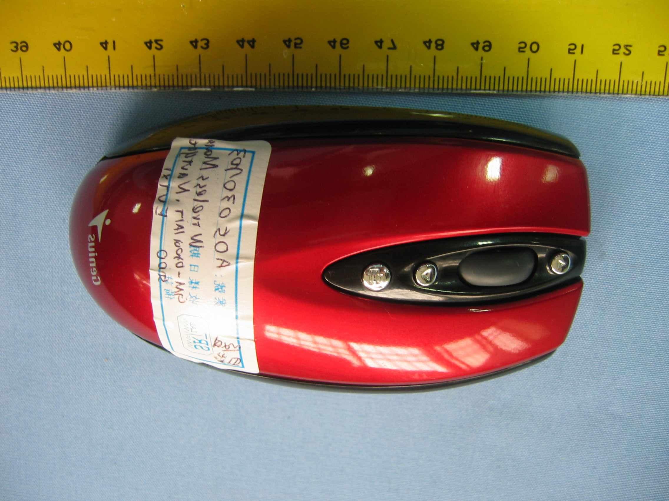
Click to zoom
Application Details
- Equipment Class
- DXX - Part 15 Low Power Communication Device Transmitter
- Date of Grant
- Apr 03, 2005
- Application Purpose
- Original Equipment
- Date of Application
- Apr 03, 2005
- Equipment Note
- WIRELESS MOUSE
- Frequency Range
- 27.04500000 - 27.04500000
- Company
- KYE SYSTEMS CORP.
- Country
- Taiwan
Documents & Files
Document Text
Text extracted from the exhibit documents filed with the FCC. Open a document above to read the original.
Users Manual
Hardware Installation 1.You can connect the receiver to a USB port of a PC 2.Install two AA batteries in the mouse. 3.Turn on your computer. 4.After you open Windows, please press the button on the receiver first and then press the button under the mouse for channel setting. Important: Remember do not put the batteries in the wrong direction, use the same types of batteries. Also, keep all drinks away! If any spill occurs on the receiver, unplug the USB connector first and clean the receiver immediately. Please switch the button to "off" under the mouse once you don't use it for a long time, and remove the batteries if you do not use this device for at least two weeks. Warning: (Troubleshooting) 1.Please do not use wireless optical mouse on a desk which is made of glass, mir- ror, iron, or black velvet. Also, a flat surface is necessary or the optical sensor will error easily. When you use wireless optical mouse on a desk that is made of metal, try using a pad and reduce the receiving distance. 2.Before the first installation is completed (channel setting ready), the mouse will not work in DOS. 3.The wireless optical mouse channel provides 256 ID-codes, and it automatically selects the ID # for your mouse. You can only set up one wireless optical mouse at a time. But if you have additional wireless optical mouse sets in an area of 10 square meters, more interference will occur between the receiver and your mouse. 4.If you feel the mouse does not move smooth as usual, then the batteries have lost their charge, so please replace them. 5.The wireless optical mouse with radio frequency gives you free movement and an enjoyable experience. For optimal performance, place the receiver at least 8 inches (about 20 cm) away from the mouse and other electrical devices, such as the computer, monitor, and etc. 1 ENGLISH Software Installation 1. Make sure the mouse is connected to the computer. 2. Put the Setup disk (or CD) into the disk drive. 3. Follow the instructions on the screen to finish the software installation. Factory Setting Changing the Faceplate Push the button underneath the mouse towards the front, and the faceplate will pop off Button Assignments 1.Left Button:Provides traditional mouse functions like click, double click and drag. 2.Right Button:You can assign this button to fre - quently used keyboard and mouse functions in ad - dition to features like Easy Jump, Auto-Panning, Zoom, etc. 3.Magic-Roller:Press the “Magic-Roller” to surf the Internet and Windows documents. 4.Back:See previous page when viewing the Inter - net. 5.Forward:Go to next page when viewing the Internet. 6.Application Switch:You can switch between ac - tive programs and documents. Button Assignments 2 FCC Compliance and Advisory Statement This device complies with Part 15 of the FCC rules. Operation is subject to the following two conditions: 1) this device may not cause harmful interference, and 2) this device must accept any interference received, including interference that may cause undesired operation. The equipment has been certified to comply with the limits for a Class B computing device pursuant to Part 15 of the FCC Rules. These limits are designed to provide reasonable protection against harmful interference in a residential installation. This equipment generates, uses, and can radiate radio frequency energy and, if not installed or used in accordance with the instructions, may cause harmful interference to radio communications. However, there is no guarantee that interference will not occur in a particular installation. If this equipment does cause harmful interference to radio or television reception, which can be determined by switching the equipment off and on. The user can try to correct the interference by the following measures: 1. Reorient or relocate the receiving antenna. 2. Increase the separation between the equipment and receiver. 3. Connect the equipment to an outlet on a circuit different from that to which the receiver is connected. 4. Consult the dealer or and experience radio/TV technician for help. Changes or modification not expressly approved by the party responsible for compliance could void the user’s authority to operate the equipment.
Block Diagram
GM-05001A/T (Wireless Navigator 5000) CONTROLLER IC EEPROM 93C46 Oscillator CRYSTAL 27.045M 2SC2712 Data Input SENSORPAN301 AmplifierAntenna CRYSTAL 16MHz KEY INPUT Z Axis INPUT
External Photos
Spectrum Research & Testing Lab., Inc. No. 101-10, Ling 8, Shan-Tong Li, Chung-Li City, Taoyuan, Taiwan, R.O.C. Photo Page:1 of1 PHOTOS OF EUT
ID Label/Location Info
Sample of FCC ID Label The device is so small that the 2 parts warning statement does not have to go on the device. It will be really hard to read. We remove the 2 parts statement from the device since we already have it in the manual. FCC ID:FSUGMZH6
Internal Photos
Spectrum Research & Testing Lab., Inc. No. 101-10, Ling 8, Shan-Tong Li, Chung-Li City, Taoyuan, Taiwan, R.O.C. Photo Page:1 of3 PHOTOS OF EUT Spectrum Research & Testing Lab., Inc. No. 101-10, Ling 8, Shan-Tong Li, Chung-Li City, Taoyuan, Taiwan, R.O.C. Photo Page:2 of3 PHOTOS OF EUT Spectrum Research & Testing Lab., Inc. No. 101-10, Ling 8, Shan-Tong Li, Chung-Li City, Taoyuan, Taiwan, R.O.C. Photo Page:3 of3 PHOTOS OF EUT
Operational Description
FCC ID:FSUGMZH6 Operational Description of equipment The EUT is an excellent tool for mobile professionals,Installtwo AAA rechargeable battery in themouse and connect the receiver to a USB port of a PC an turn on your computer. PRODUCT Wireless Mouse MODEL NO. GM-05001A/T,Navigator 5000 POWER REQUIREMENTS +3V DC at50mA(MAX) FREQUENCY BAND 27MHz CARRIER FREQUENCY 27.045 MHz NUMBER OF CHANNEL 1 RESOLUTION 800 DPI RATED RF OUTPUT POWER 51dBuV ~ 53 dBuV@3m MCU TYPE MDT10P22 SENSOR TYPE PAN301 MODE OF OPERATION Simplex ANTENNA TYPE Loop antenna
Schematics
L_SW C16 30P SW8 POW ER SW GND C5 22p R14 5.6K C29 27P R23100KVRF C2 47u GND C23 6800p SW4 B4 DO R155.6K R12 5.6K VDD Q2 2SC2714 R18100K 2 B4 Z2 L52.5uH R20100K C24 NC C21 6800P CS R10 8.2K ID_SW BT1 3V L4 1000nH SW2 M R26 100K R8 10 B4 C25 68P ID_SW R17 330 C12390P 3 Z1 PDS C180 B5 D1 1N5817 12 C13 30P SW6 APP R21100K C30 0.1u U4 93C46 1 2 3 45 6 7 8 S C D QVSS ORG DU VCC GND DI C8 0.22u Date: 2005-1-17 Rev:1 New VDD Z1 C33 1u CS B5 C19 C27 470P VDD ALPS A B C EC1 Encoder DIY A GND Q1 3906 Z1 SW5 B5 R24100K U2 XC6385 1 23 VSS OUTLX VDD L_SW R ESET SDIO R11 27K CLK C3 47u APP C20 20P X1 27.045M R22100K APP C15 220P C17 470P PCB R547K VBAT Q3 2SC2712 R27 0 DI SCLK DO Y3 16M D2 LED VDD Z2 CLK R28 100 Z2 C1 47u Q4 MPSH10 VDD R ESET SW1 L DI SCLK C22 VDD DRW: མ ֮ C11 0.1u R25100K C4 22p R13 5.6K C31 1u L1 220UH 12 VRF CKT: 21010015101 PCB:1 GM-05001A/T (Wireless Nav igator 5000) B 11Thursday , March 17, 2005 Title SizeDocument NumberRev Date:Sheet of M_SW R _SW C34 0.1u R19100K VDD SDIO SW3 R R _SW R65.6K R2 47K R9 15K C14 100P CLK C26 6800p CHK: VDD GND Y1 CRY STAL M_SW U1 MDT10P22 2 3 4 5 6 7 8 9 10 11 1213 14 15 16 17 18 19 20 21 22 23 124 PA7 PA5 PA2 PA3 R TCC MCLR VSS PB0 PB1 PB2 PB3PB4 PB5 PB6 PB7 VDD OSC2 OSC1 PA0 PA1 PA4 PA6 NCNC R16 1.5K GND R710 SW7 LINK 1 L6 APR: R4 100K VDD C28 5P U5 PAN301 1 2 3 4 5 6 7 8 9 1011 12 13 14 15 16 17 18 19 20 VSS_LED LED OSCOUT OSCIN NC VSSD VSSA VDD VREFA VREFBYA YB XA XB NC NC NC SCLK SDIO PD C32 0.1u PDS L3 1000nH
Test Report
Spectrum Research & Testing Lab., Inc. No. 101-10, Ling 8, Shan-Tong Li, Chung-Li City, Taoyuan, Taiwan, R.O.C. TEST REPORT Reference No.:A05030703 Report No.:FCCA05030703 Page:2 of 18 Date:Mar. 10, 2005 FCC ID:FSUGMZH6 Table of Contents 1. DOCUMENT POLICY AND TEST STATEMENT................................................ 3 1.1 DOCUMENT POLICY ........................................................................................ 3 1.2 TEST STATEMENT............................................................................................ 3 1.3 EUT MODIFICATION ......................................................................................... 3 2. DESCRIPTION OF EUT AND TEST MODE ...................................................... 4 2.1 GENERAL DESCRIPTION OF EUT .................................................................. 4 2.2 DESCRIPTION OF EUT INTERNAL DEVICE.................................................... 4 2.3 DESCRIPTION OF TEST MODE ....................................................................... 4 2.4 DESCRIPTION OF SUPPORT UNIT ................................................................. 5 3. DESCRIPTION OF APPLIED STANDARDS ...................................................... 5 4. CONDUCTED EMISSION TEST ........................................................................ 6 4.1 CONDUCTED EMISSION LIMIT........................................................................ 6 4.2 TEST EQUIPMENT............................................................................................ 6 4.3 TEST SETUP..................................................................................................... 7 4.4 TEST PROCEDURE .......................................................................................... 7 4.5 EUT OPERATING CONDITION ......................................................................... 7 4.6 TEST RESULT ................................................................................................... 8 5. RADIATED EMISSION TEST ............................................................................. 9 5.1 RADIATED EMISSION LIMIT............................................................................. 9 5.2 TEST EQUIPMENT...........................................................................................10 5.3 TEST SET-UP...................................................................................................11 5.4 TEST PROCEDURE .........................................................................................12 5.5 EUT OPERATING CONDITION ........................................................................12 5.6 RADIATED EMISSION TEST RESULT.............................................................13 6. PHOTOS OF TESTING.................................................................................... 15 7. TERMS OF ABRIVATION................................................................................. 18 Spectrum Research & Testing Lab., Inc. No. 101-10, Ling 8, Shan-Tong Li, Chung-Li City, Taoyuan, Taiwan, R.O.C. TEST REPORT Reference No.:A05030703 Report No.:FCCA05030703 Page:3 of 18 Date:Mar. 10, 2005 FCC ID:FSUGMZH6 1. DOCUMENT POLICY AND TEST STATEMENT 1.1 DOCUMENT POLICY - The report shall not be reproduced except in full, without the written approval of SRT Lab, Inc. - The report must not be used by the applicant to claim that the product is endorsed by NVLAP, TÜV, NEMKO and SRT. - The NVLAP logo applies only to the applicable standards specified in this report. 1.2 TEST STATEMENT - The test results in the report apply only to the unit tested by SRT Lab. - There was no deviation from the requirements of test standards during the test. - AC power source, 120 Vac/60 Hz, was used during the test. 1.3 EUT MODIFICATION - No modification in SRT Lab. Spectrum Research & Testing Lab., Inc. No. 101-10, Ling 8, Shan-Tong Li, Chung-Li City, Taoyuan, Taiwan, R.O.C. TEST REPORT Reference No.:A05030703 Report No.:FCCA05030703 Page:4 of 18 Date:Mar. 10, 2005 FCC ID:FSUGMZH6 2. DESCRIPTION OF EUT AND TEST MODE 2.1 GENERAL DESCRIPTION OF EUT PRODUCT Wireless Mouse MODEL NO. GM-05001A/T, Navigator 5000 POWER REQUIREMENTS +3V DC at 50mA(MAX) FREQUENCY BAND 27MHz CARRIER FREQUENCY 27.045 MHz NUMBER OF CHANNEL 1 RESOLUTION 800 DPI RATED RF OUTPUT POWER 51dBuV ~ 53 dBuV@3m MCU TYPE MDT10P22 SENSOR TYPE PAN301 MODE OF OPERATION Simplex ANTENNA TYPE Loop antenna NOTE : The EUT has two model numbers as below on market. They are identical in all aspects except for the customer. For more detailed features, please refer to the manufacturer’s specification or User’s Manual. 2.2 DESCRIPTION OF EUT INTERNAL DEVICE DEVICE BRAND / MAKER MODEL # FCC ID/DOC REMARK N/A 2.3 DESCRIPTION OF TEST MODE N/A (It is only applicable to more than one test mode.) Spectrum Research & Testing Lab., Inc. No. 101-10, Ling 8, Shan-Tong Li, Chung-Li City, Taoyuan, Taiwan, R.O.C. TEST REPORT Reference No.:A05030703 Report No.:FCCA05030703 Page:5 of 18 Date:Mar. 10, 2005 FCC ID:FSUGMZH6 2.4 DESCRIPTION OF SUPPORT UNIT The EUT was configured by the requirement of ANSI C63.4:2003 and CISRP22:2003. All interface ports were connected to the appropriate support units via specific cables. The support units and cables are listed below. NO DEVICE BRAND MODEL # FCC ID/DOC CABLE 1 NOTEBOOK COMPAQ B200 DOC 1.5m unshielded power cord 1.2m shielded data cable 2 MODEM ACEEX DM-1414 DOC 1.5m unshielded power cord 1.5m shielded data cable 3 PRINTER EPSON STYLUS C20SX DOC 1.8m unshielded power cord 1.5m shielded data cable 4 RECEIVER KYE GK-04002A/R FSUGMZGV N/A 5 NOTE : For the actual test configuration, please refer to the photos of testing. 3. DESCRIPTION OF APPLIED STANDARDS The EUT is a kind of wireless product and to be connected with a PC system for normal use. According to the specifications provided by the applicant, it must comply with the requirements of the following standards: 47 CFR Part 15, Subpart C ANSI C63.4:…
Text truncated - open the document above for the full version.
Test Setup Photos
PHOTOS OF TESTING - Conducted test - Radiated test (TX) - Radiated test (RX)
Contact Information
Applicant
Ricky Chen(Section Supervisor)
Test Firm
Spectrum Research & Testing Lab.Linda Chiang
Technical Specifications
| # | Rule Parts | Frequency Range | Power Output |
|---|---|---|---|
| 1 | 15C | 27.045 MHz - 27.045 MHz | - |
Other Applications from KYE SYSTEMS CORP.
FSUGG0AM
Aug 20, 2026Wireless Speaker
Equipment Class
DSS - Part 15 Spread Spectrum Transmitter
FSUGKZI2
May 23, 2026Wireless Keyboard
Equipment Class
DXX - Part 15 Low Power Communication Device TransmitterFSUGMZN6
Apr 20, 2026Wireless Mouse
Equipment Class
DTS - Digital Transmission SystemFSUGMZN4
Apr 03, 2026Wireless Mouse
Equipment Class
DXX - Part 15 Low Power Communication Device TransmitterFSUGMZN7
Apr 01, 2026Wireless Mouse
Equipment Class
DTS - Digital Transmission System