FSUGMZH7Wireless Mouse
KYE SYSTEMS CORP.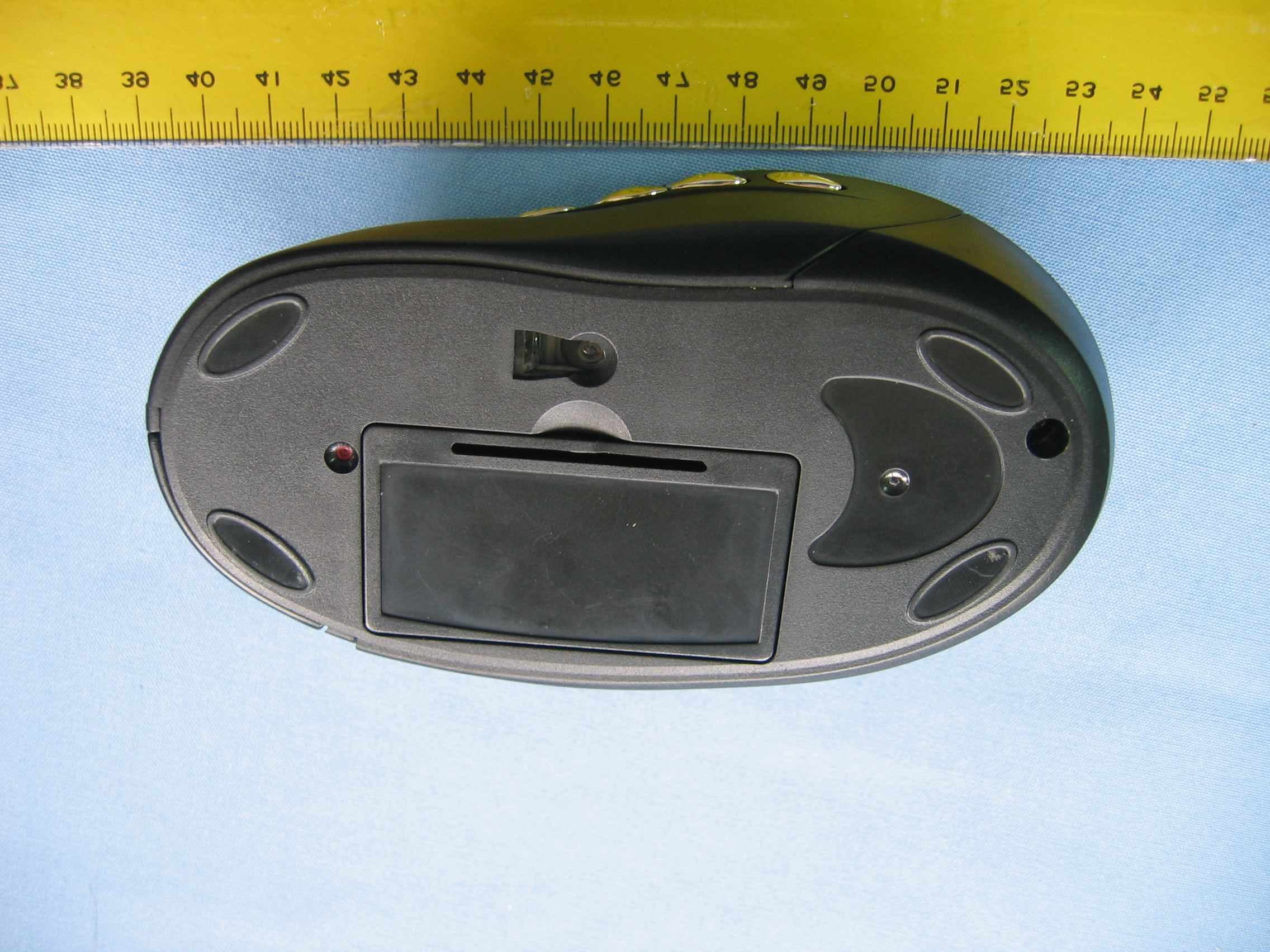
Click to zoom
Application Details
- Equipment Class
- DXX - Part 15 Low Power Communication Device Transmitter
- Date of Grant
- Apr 05, 2005
- Application Purpose
- Original Equipment
- Date of Application
- Apr 05, 2005
- Equipment Note
- Wireless Mouse
- Frequency Range
- 27.04500000 - 27.04500000
- Company
- KYE SYSTEMS CORP.
- Country
- Taiwan
Documents & Files
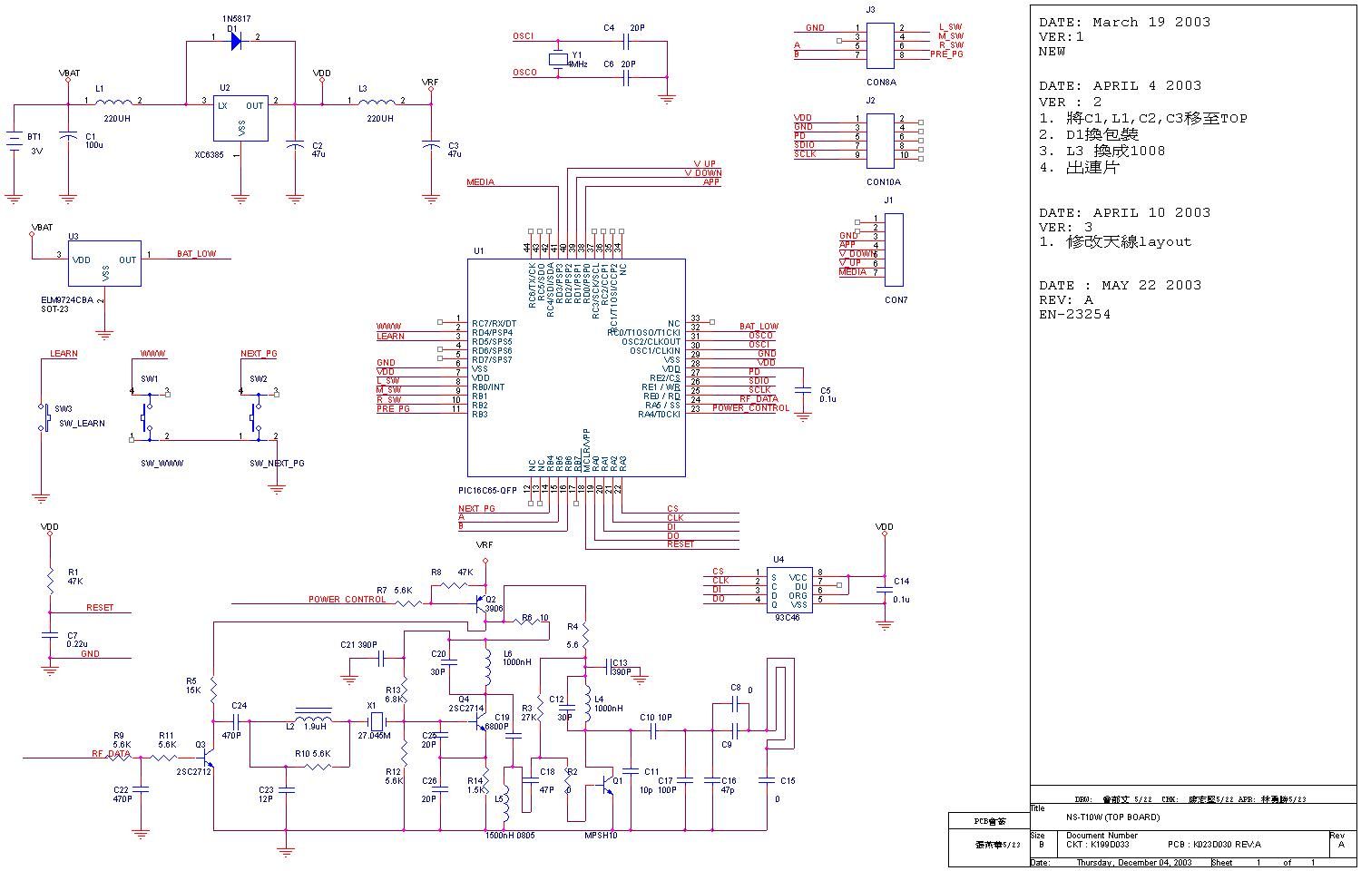
Document Text
Text extracted from the exhibit documents filed with the FCC. Open a document above to read the original.
Users Manual
Hardware Installation 1.You can connect the receiver to a USB port of a PC 2.Install two AA batteries in the mouse. 3. Turn on your computer. 4.After you open Windows, please press the button on the receiver first and then press the button under the mouse for channel setting. Important: You can use the battery charger receiver to recharge two AA each time when you use the PC. Plug the battery charger receiver USB connector into the PC directly and remember do not put the batteries in the wrong direction, use the same types of batteries, and do not recharge via the USB hub, that will make your receiver, main-board and hub burn or become non-usable easily. Also, keep all drinks away! If any spill occurs on the receiver, unplug the USB connector first and clean the receiver immediately. Please remove the batteries if you do not use this de - vice for at least two weeks. Warning: (Troubleshooting) 1.Please do not use Wireless optical mouse on a desk which is made of glass, mir - ror, iron, or black velvet. Also, a flat surface is necessary or the Optical Sensor will error easily. When you use Wireless optical mouse on a desk that is made of metal, try using a pad and reduce the receiving distance. 2.Before the first installation is completed (channel setting ready), the mouse will not work. 3.The Wireless optical mouse channel provides 256 ID-codes, and it automatically selects the ID # for your mouse. You can only set up one Wireless optical mouse at a time. But if you have additional Wireless optical mouse sets in an area of 10 square meters, more interference will occur between the receiver and your mouse. 1 ENGLISH 4.If you feel the mouse does not move smooth as usual, then the batteries have lost their charge, so please replace them. Also, the wireless icon will be blinking “red” when there is a battery-low situation. The LED on the receiver shows the battery-recharging status (from shining to LED completely “on” for battery full). You should set up the channel every time you replace the batteries. 5.If you need to buy new batteries, please choose Ni-MH (Nickel-Metal-Hydride) AA batteries, 1.2V, 1300 to 1600 mAH.Please do not mix or use other types of batteries (Li-ion, Ni-Cd, Alkaline, etc.) 6.The Wireless optical mouse with radio frequency gives you free movement and an enjoyable experience. For optimal performance, place the receiver at least 8 inches (about 20 cm) away from the mouse and other electrical devices, such as the computer, monitor, and etc. Software Installation 1. Make sure the mouse is connected to the computer. 2. Put the Setup disk (or CD) into the disk drive. 3. Follow the instructions on the screen to finish the software installation. Factory Setting 2 10 “One Touch” keys for fast access to multimedia, the Internet, and the application switch. Button Assignments The Button Assignment feature lets you work in a more efficient way because you can assign the most frequently used commands in Windows to the mouse buttons. 1.Left Button:Provides traditional mouse functions like click, double click and drag. 2.Right Button:You can assign this button to fre- quently used keyboard and mouse functions in addi- tion to features like Easy Jump, Auto-Panning, Zoom, etc. 3.Magic-Roller:Press the “Magic-Roller” to surf the Internet and Windows documents 4.Back:See previous page when viewing the Internet 5.Forward:Go to next page when viewing the Internet 6.WWW:Open browser (Netscape or IE) 7.Play & Pause:Play and pause of audio or video CD’s 8.Vol. +:Increase volume 9.Vol. -:Decrease volume 10.Application Switch:You can switch between active programs and documents 3 FCC Compliance and Advisory Statement This device complies with Part 15 of the FCC rules. Operation is subject to the following two conditions: 1) this device may not cause harmful interference, and 2) this device must accept any interference received, including interference that may cause undesired operation. The equipment has been certified to comply with the limits for a Class B computing device pursuant to Part 15 of the FCC Rules. These limits are designed to provide reasonable protection against harmful interference in a residential installation. This equipment generates, uses, and can radiate radio frequency energy and, if not installed or used in accordance with the instructions, may cause harmful interference to radio communications. However, there is no guarantee that interference will not occur in a particular installation. If this equipment does cause harmful interference to radio or television reception, which can be determined by switching the equipment off and on. The user can try to correct the interference by the following measures: 1. Reorient or relocate the receiving antenna. 2. Increase the separation between the equipment and receiver. 3. Connect the equipment to an outlet on a circuit different from that to which the receiver is connected. 4. Consult the dealer or and experience radio/TV technician for help. Changes or modification not expressly approved by the party responsible for compliance could void the user’s authority to operate the equipment.
External Photos
Spectrum Research & Testing Lab., Inc. No. 101-10, Ling 8, Shan-Tong Li, Chung-Li City, Taoyuan, Taiwan, R.O.C. Photo Page:1 of2 PHOTOS OF EUT Spectrum Research & Testing Lab., Inc. No. 101-10, Ling 8, Shan-Tong Li, Chung-Li City, Taoyuan, Taiwan, R.O.C. Photo Page:2 of2 PHOTOS OF EUT
ID Label/Location Info
Sample of FCC ID Label The device is so small that the 2 parts warning statement does not have to go on the device. It will be really hard to read. We remove the 2 parts statement from the device since we already have it in the manual. FCC ID:FSUGMZH7
Internal Photos
Spectrum Research & Testing Lab., Inc. No. 101-10, Ling 8, Shan-Tong Li, Chung-Li City, Taoyuan, Taiwan, R.O.C. Photo Page:1 of6 PHOTOS OF EUT Spectrum Research & Testing Lab., Inc. No. 101-10, Ling 8, Shan-Tong Li, Chung-Li City, Taoyuan, Taiwan, R.O.C. Photo Page:2 of6 PHOTOS OF EUT Spectrum Research & Testing Lab., Inc. No. 101-10, Ling 8, Shan-Tong Li, Chung-Li City, Taoyuan, Taiwan, R.O.C. Photo Page:3 of6 PHOTOS OF EUT
Internal Photos
Spectrum Research & Testing Lab., Inc. No. 101-10, Ling 8, Shan-Tong Li, Chung-Li City, Taoyuan, Taiwan, R.O.C. Photo Page:4 of6 PHOTOS OF EUT Spectrum Research & Testing Lab., Inc. No. 101-10, Ling 8, Shan-Tong Li, Chung-Li City, Taoyuan, Taiwan, R.O.C. Photo Page:5 of6 PHOTOS OF EUT
Internal Photos
Spectrum Research & Testing Lab., Inc. No. 101-10, Ling 8, Shan-Tong Li, Chung-Li City, Taoyuan, Taiwan, R.O.C. Photo Page:6 of6 PHOTOS OF EUT
Operational Description
FCC ID:FSUGMZH7 Operational Description of equipment The EUT is an excellent tool for mobile professionals,Installtwo AAA rechargeable battery in themouse and connect the receiver to a USB port of a PC an turn on your computer. PRODUCT WirelessMouse MODEL NO. GK-05002U/T, Ergo R5000 POWER SUPPLY 3Vdc from battery (1.5V x 2) FREQUENCY BAND 27MHz CARRIER FREQUENCY 27.045 MHz NUMBER OF CHANNEL 1 CHANNEL SPACING 10KHz CHANNEL BANDWIDTH 10KHz RATED RF OUTPUT POWER 54dB Ӵ V I.F. & L.O. I.F.:455KHz, L.O.:26.59MHz MODULATION TYPE FSK MODE OF OPERATION Simplex DUTY CYCLE 50% BIT RATE OF TRANSMISSION 3.125KHz OPERATING TEMPERATURE RANGE 25 ANTENNA TYPE Loop antenna
Test Report
Spectrum Research & Testing Lab., Inc. No. 101-10, Ling 8, Shan-Tong Li, Chung-Li City, Taoyuan, Taiwan, R.O.C. TEST REPORT Reference No.:A05022508 Report No.:FCCA05022508 Page:2 of22 22 Date:Mar. 08, 2005 FCC ID:FSUGMZH7 Table of Contents 1. DOCUMENT POLICY AND TEST STATEMENT................................................3 1.1 DOCUMENT POLICY.........................................................................................3 1.2 TEST STATEMENT.............................................................................................3 1.3 EUTMODIFICATION.........................................................................................3 2. DESCRIPTION OF EUT AND TEST MODE......................................................4 2.1 GENERAL DESCRIPTION OF EUT...................................................................4 2.2 DESCRIPTION OF EUT INTERNAL DEVICE.....................................................4 2.3 DESCRIPTION OFTEST MODE........................................................................4 2.4 DESCRIPTION OFSUPPORT UNIT..................................................................5 3. DESCRIPTION OF APPLIED STANDARDS......................................................5 4. CONDUCTED EMISSION TEST........................................................................6 4.1CONDUCTED EMISSION LIMIT.........................................................................6 4.2 TEST EQUIPMENT.............................................................................................6 4.3 TEST SETUP......................................................................................................7 4.4 TEST PROCEDURE...........................................................................................7 4.5 EUT OPERATING CONDITION..........................................................................7 4.6TEST RESULT....................................................................................................8 5. RADIATED EMISSION TEST...........................................................................10 5.1 RADIATED EMISSION LIMIT............................................................................10 5.2 TEST EQUIPMENT...........................................................................................11 5.3 TEST SET-UP...................................................................................................12 5.4 TEST PROCEDURE.........................................................................................13 5.5 EUT OPERATING CONDITION........................................................................13 5.6 RADIATED EMISSION TESTRESULT.............................................................14 6. PHOTOS OF TESTING....................................................................................17 7. TERMS OF ABRIVATION.................................................................................22 Spectrum Research & Testing Lab., Inc. No. 101-10, Ling 8, Shan-Tong Li, Chung-Li City, Taoyuan, Taiwan, R.O.C. TEST REPORT Reference No.:A05022508 Report No.:FCCA05022508 Page:3 of22 22 Date:Mar. 08, 2005 FCC ID:FSUGMZH7 1. DOCUMENT POLICY AND TEST STATEMENT 1.1 DOCUMENT POLICY - The report shall not be reproduced except in full, without the written approval of SRT Lab, Inc. - The report must not be used by the applicant to claim that the product is endorsed by NVLAP, TV, NEMKO and SRT. - The NVLAP logo applies only to the applicable standards specified in this report. 1.2 TEST STATEMENT - The test results in the report apply only to the unit tested by SRT Lab. - There was no deviation from the requirements of test standards during the test. - AC power source, 120 Vac/60 Hz, was used during the test. 1.3 EUTMODIFICATION - No modification in SRT Lab. Spectrum Research & Testing Lab., Inc. No. 101-10, Ling 8, Shan-Tong Li, Chung-Li City, Taoyuan, Taiwan, R.O.C. TEST REPORT Reference No.:A05022508 Report No.:FCCA05022508 Page:4 of22 22 Date:Mar. 08, 2005 FCC ID:FSUGMZH7 2. DESCRIPTION OF EUT AND TEST MODE 2.1 GENERAL DESCRIPTION OF EUT PRODUCT WirelessMouse MODEL NO. GK-05002U/T, Ergo R5000 POWER SUPPLY 3Vdc from battery (1.5V x 2) FREQUENCY BAND 27MHz CARRIER FREQUENCY 27.045 MHz NUMBER OF CHANNEL 1 CHANNEL SPACING 10KHz CHANNEL BANDWIDTH 10KHz RATED RF OUTPUT POWER 54dB Ӵ V I.F. & L.O. I.F.:455KHz, L.O.:26.59MHz MODULATION TYPE FSK MODE OF OPERATION Simplex DUTY CYCLE 50% BIT RATE OF TRANSMISSION 3.125KHz OPERATING TEMPERATURE RANGE 25 ANTENNA TYPE Loop antenna NOTE : The EUT has two model numbers as below on market. They are identical in all aspects except for the customer. For more detailed features, please refer to the manufacturer speci fi cat ion or Us er Man ual . 2.2 DESCRIPTION OF EUT INTERNAL DEVICE DEVICEBRAND / MAKERMODEL #FCC ID/DOCREMARK N/A 2.3 DESCRIPTION OF TEST MODE The EUT was tested for emission measurement underthe following situations: Mode 1Link 2Charger Spectrum Research & Testing Lab., Inc. No. 101-10, Ling 8, Shan-Tong Li, Chung-Li City, Taoyuan, Taiwan, R.O.C. TEST REPORT Reference No.:A05022508 Report No.:FCCA05022508 Page:5 of22 22 Date:Mar. 08, 2005 FCC ID:FSUGMZH7 2.4 DESCRIPTION OF SUPPORT UNIT The EUT was configured by the requirement of ANSI C63.4:2003 and CISRP22:2003. All interface ports were connected to the appropriate support units via specific cables. The support units and cables are listed below. NODEVICEBRANDMODEL #FCC ID/DOCCABLE 1 NOTEBOOKCOMPAQB200DOC 1.5m unshielded power cord 1.2m shielded data cable 2 MODEMACEEXDM-1414DOC 1.5m unshielded power cord 1.5m shieldeddata cable 3 PRINTEREPSONSTYLUS C20SXDOC 1.8m unshielded power cord 1.5m shielded data cable 4 RECEIVER+ CHARGER KYEGK-05002/RDOC1.5m unshielded data cable 5 NOTE : For the actual test configuration, please refer to the photos of testing. 3. DESCRIPTION OF APPLIED STANDARDS The EUT is a kind ofwireless product and to be connected with a PC system for normal use. According to the specific…
Text truncated - open the document above for the full version.
Test Setup Photos
PHOTOS OF TESTING - Conducted test (Mode 1: Link) - Conducted test (Mode 2: Charger) - Radiated test (TX) - Radiated test (RX-Link) - Radiated test (RX-Charger)
Contact Information
Applicant
Ricky Chen(Section Supervisor)
Test Firm
Spectrum Research & Testing Lab.Linda Chiang
Technical Specifications
| # | Rule Parts | Frequency Range | Power Output |
|---|---|---|---|
| 1 | 15C | 27.045 MHz - 27.045 MHz | - |
Other Applications from KYE SYSTEMS CORP.
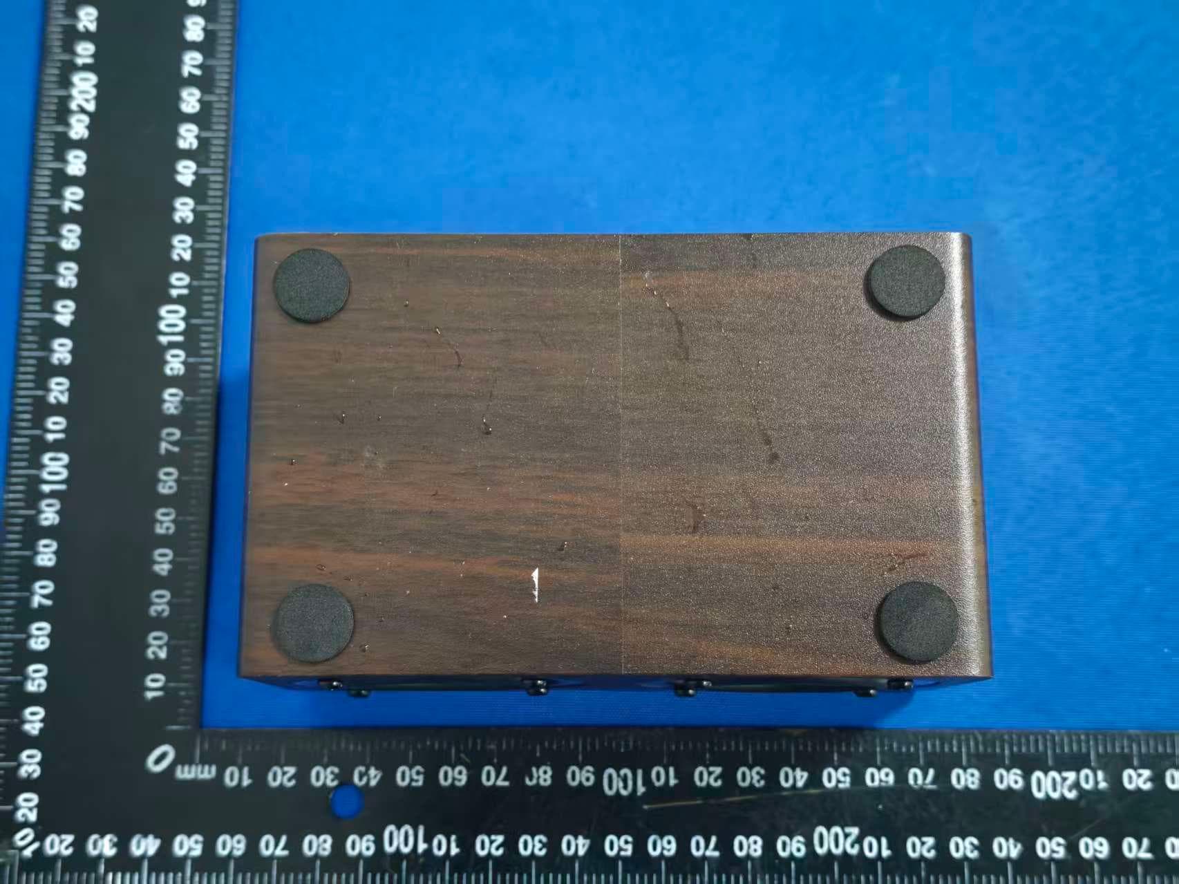
FSUGG0AM
Aug 20, 2026Wireless Speaker
Equipment Class
DSS - Part 15 Spread Spectrum Transmitter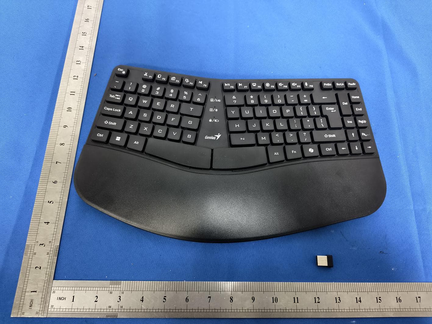
FSUGKZI2
May 23, 2026Wireless Keyboard
Equipment Class
DXX - Part 15 Low Power Communication Device TransmitterFSUGMZN6
Apr 20, 2026Wireless Mouse
Equipment Class
DTS - Digital Transmission SystemFSUGMZN4
Apr 03, 2026Wireless Mouse
Equipment Class
DXX - Part 15 Low Power Communication Device TransmitterFSUGMZN7
Apr 01, 2026Wireless Mouse
Equipment Class
DTS - Digital Transmission System