FSUGMZHDTRAVELER 1000
KYE SYSTEMS CORP.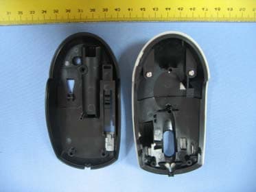
Click to zoom
Application Details
- Equipment Class
- DXX - Part 15 Low Power Communication Device Transmitter
- Date of Grant
- Jan 18, 2006
- Application Purpose
- Original Equipment
- Date of Application
- Jan 18, 2006
- Equipment Note
- TRAVELER 1000
- Frequency Range
- 27.04500000 - 27.04500000
- Company
- KYE SYSTEMS CORP.
- Country
- Taiwan
Documents & Files
Document Text
Text extracted from the exhibit documents filed with the FCC. Open a document above to read the original.
Users Manual
Hardware Installation 1.You can connect the receiver to a USB port of a PC 2.Install one AA battery in the mouse. 3.Turn on your computer. 4.After you open Windows, please press the button on the receiver first and then press the button under the mouse for channel setting. Important: Remember do not put the batteries in the wrong direction, use the same types of batteries. Also, keep all drinks away! If any spill occurs on the receiver, unplug the USB connector first and clean the receiver immediately. Please switch the button to "off" under the mouse once you don't use it for a long time, and remove the batteries if you do not use this device for at least two weeks. Warning: (Troubleshooting) 1.Please do not use Wireless optical mouse on a desk which is made of glass, mir - ror, iron, or black velvet. Also, a flat surface is necessary or the Optical Sensor will error easily. When you use Wireless optical mouse on a desk that is made of metal, try using a pad and reduce the receiving distance. 1 ENGLISH 2.Before the first installation is completed (channel setting ready), the mouse will not work in DOS. 3.The Wireless optical mouse channel provides 256 ID-codes, and it automatically selects the ID # for your mouse. You can only set up one Wireless optical mouse at a time. But if you have additional Wireless optical mouse sets in an area of 10 square meters, more interference will occur between the receiver and your mouse. 4.If you feel the mouse does not move smooth as usual, then the batteries have lost their charge, so please replace them. 5.The Wireless optical mouse with radio frequency gives you free movement and an enjoyable experience. For optimal performance, place the receiver at least 8 inches (about 20 cm) away from the mouse and other electrical devices, such as the computer, monitor, and etc. Software Installation 1. Make sure the mouse is connected to the computer. 2. Put the Setup disk (or CD) into the disk drive. 3. Follow the instructions on the screen to finish the software installation. Factory Setting 2 Button Assignments The Button Assignment feature lets you work in a more efficient way because you can assign the most fre - quently used commands in Windows to the mouse but - tons. Magic-RollerPress the “Magic-Roller” to surf the Internet and Windows documents Horizontal Scroll Press the roller to the left and the cursor scrolls to the left; press the roller to the right and the cursor scrolls to the right. Left ButtonProvides traditional mouse functions such as click, double click and drag. Right ButtonYou can assign this button frequently used keyboard and mouse func - tions in addition to features like EasyJump, Auto-Panning, Zoom, etc. Roller ButtonYou can assign this button frequently used keyboard and mouse func- tions in addition to features like EasyJump, Auto-Panning, Zoom, etc. 3 FCC Compliance and Advisory Statement This device complies with Part 15 of the FCC rules. Operation is subject to the following two conditions: 1) this device may not cause harmful interference, and 2) this device must accept any interference received, including interference that may cause undesired operation. The equipment has been certified to comply with the limits for a Class B computing device pursuant to Part 15 of the FCC Rules. These limits are designed to provide reasonable protection against harmful interference in a residential installation. This equipment generates, uses, and can radiate radio frequency energy and, if not installed or used in accordance with the instructions, may cause harmful interference to radio communications. However, there is no guarantee that interference will not occur in a particular installation. If this equipment does cause harmful interference to radio or television reception, which can be determined by switching the equipment off and on. The user can try to correct the interference by the following measures: 1. Reorient or relocate the receiving antenna. 2. Increase the separation between the equipment and receiver. 3. Connect the equipment to an outlet on a circuit different from that to which the receiver is connected. 4. Consult the dealer or and experience radio/TV technician for help. Changes or modification not expressly approved by the party responsible for compliance could void the user’s authority to operate the equipment.
Block Diagram
CY7C63743 12MHzTRF7903 EEROM MATCH CIRCUIT ANTENNA 6MHz DATA USB+PS2 POWER LED GM-050016A-T MCU+SENSOR PAN3202DI CLK 16Mhz Z Axis Input R,L,M Switch Input Tilt Wheel Input RF_DATA RF_POWER
External Photos
Spectrum Research & Testing Lab., Inc. No. 101-10, Ling 8, Shan-Tong Li, Chung-Li City, Taoyuan, Taiwan, R.O.C. Photo Page: 1 of 11 PHOTOS OF EUT Spectrum Research & Testing Lab., Inc. No. 101-10, Ling 8, Shan-Tong Li, Chung-Li City, Taoyuan, Taiwan, R.O.C. Photo Page: 3 of 11 PHOTOS OF EUT
ID Label/Location Info
Sample of FCC ID Label The device is so small that the 2 parts warning statement does not have to go on the device. It will be really hard to read. We remove the 2 parts statement from the device since we already have it in the manual. FCC ID: FSUGMZHD
Internal Photos
Spectrum Research & Testing Lab., Inc. No. 101-10, Ling 8, Shan-Tong Li, Chung-Li City, Taoyuan, Taiwan, R.O.C. Photo Page: 4 of 11 PHOTOS OF EUT
Operational Description
FCC ID: FSUGMZHD Operational Description of equipment The EUT is an excellent tool for mobile professionals. Install an AA battery in the mouse and connect the receiver to a USB port of the PC, then turn on your computer. PRODUCT Traveler 1000 MODEL NO. GM-050016A-R, GM-050016A-T POWER REQUIREMENTS DC 5V(R) DC 1.5V(T) FREQUENCY BAND 27MHz CARRIER FREQUENCY 27.045 MHz CHANNEL BANDWIDTH 50KHz NUMBER OF CHANNEL 1 RATED RF OUTPUT POWER 52 dBuV (T) MODE OF OPERATION Simplex ANTENNA TYPE Loop The EUT has two model numbers as below on the market. They are identical in all aspects except for the customer. For more detailed features, please refer to the manufacturer’s specification or User’s Manual.
Schematics
RF_GND RF_DATA RF_VCCC1447PF 0603 R11K 0603 RF_VCC_IN VCC RF_GND USBCON R14 33 0603 R7 10 0603 C8 2.2uF 0805 C910uF 0805 R121.2K 0603 R13 33 0603 J1CON41234 RF_GND R11 10 0603 C1910uF 0805 U2 CY 7C63743 SSOP 1234 24232221 5 20 161514119101213 P0.0P0.1P0.2P0.3P0.4P0.5P0.6P0.7P1.0P1.1 D+/Sclk D-/Sdata Vcc Vreg VssVpp Xt l _ I n Xt l _ O u t C23 10uF Case A C11 10nF 0603 1.RF Y1 12MHz C240.1uF 0603 RF_DATA C710uF 0805 R16 10K 0603 2.RF RF_VCC RF_GND U1 TRF7903-PW20 123456789 10 20191817161514131211 ANT_IN1AGND1VPOSVCCVDIGXTA L _ I NXTA L _ O U TVNEG_DIGB3B2 ANT_IN2 VNEG MD R LF AGND2 VPOS_LO VNEG_LO B1 OUT CLK DATA_LED RF_VCC R9330 0603 VDD 0805 VDD C260.1uF 0603 LED1DATA_LED 1 2 C610nF 0603 C410uF Case A Q12N3906 1 2 3 RF_GND 0805 DATA_LED C5 0.1uF 0603 U393C46 78 1234 56 NCVCC CS SKD1 DO GNDNC R15 1K 0603 0805 RF_GND C10 6.8nF 0603 Q22N3906 1 2 3 C18 10nF 0603 VDD 1. ( ) PCAB:20000684101 SPCBA:21000402101 Circuit:21010019101 1 RS,GM-05005U,RX,USB,KY E,27M,800DPI B 11 Tuesday , August 30, 2005 Tit leSize Document Number Rev Date: Sheet of C25 10uF Case A 12 SW1 C1747PF 0603 C22 0.1uF 0603 1.RF C1210uF 0805 C1 33P 0603 2. ( ) C2 39PF 0603 1 C160.1UF0603 12 C290.1UFCC0603 DRW: 9/28 C97P CC0402 12 DATE:2005-09-28REV : 3REMOV E C2 7, C28CHA NGE DC TODC SOLUTION C20 0.1UF 0603 12 SW5ZX2OMROM DIP2 12 SW4ZX1OMROM DIP2 12 R11 470KRC0603 BT11.5VSPRING 12 RF_DATA Q2 MPSH 10SOT-23 1 3 2 R568K RC0402 1 2 CHK: L21000nH 1008 12 VDD L1 33UHCSN054D 1 2 Z1 C180.1UF0603 12 C2115P 06030603 1 2 APR:Date:2005-08-22Re v : 1Ne w R612 RC0402 1 2 C710nF CC040212 U3 24AA02 SO8 1234 5678 A0A1A2GND SDA SCL WP VDD Z2 Y1CRYSTALDIP2 1 2 VRF C310.1UFCC0603 ANT1PIFAPRINT 1 ISDA U4 AIC1620MSOP-8 1234 5678 FBLBIN-LOBREF N-SHDN GND LX OUT CKT:20010445101 3 GM-050016U Traveler 1000/USB TX B 11 Monday , October 17, 2005 Tit leSize Document Number Rev Date: Sheet of C13100P CC0402 12 C1020P CC0402 12 ZX1 SW1LMICRO DIP3 12 R147K RC0603 12 R85.6K RC0402 1 2 R412RC0402 12 LINK_B Q12N3906SOT-23 1 23 B OSCO ISDA L_B OSCI C120.1UFRC0603 R121M RC0603 Q33904SOT-23 1 3 2 VBAT C51500PCC0402 12 U2 PAN3202DI 4D5B Shrunk DIP24 123456789 101112 131415161718192021222324 ZY1ZY2BLB4LEDOSC_OUTOSC_INVDDDVSSVDDVDDAVREF B5 NC ISCKISDA RFID RF_DATA RF_EN BRBM NC1 ZX2ZX1 ISCK RF_DATA C1510UF1206 12 C141UF0603 12 C247UFB-CASE 12 VDD ZX1 SW3MZIPPY DIP2 12 M_B D2IR LEDOD5mm 12 OSCI L_B R10 24 OHM R0603 12 C171UF0603 12 OSCO Z2 VRF C300.1UFCC0603 R25.6KRC0402 12 VDD SW2RMICRO DIP3 12 C246800PFRC060312 C ZX2 VDD C25NC RC0603 12 RF_POWER C430P CC0603 12 C27 47UF B-CASE 12 LINK_B E SW7LINKSMD 4PIN 12 C1915P0603 1 2 R9180RC0402 12 X1 27.042MHC_49US 1 2 R733K RC0402 1 2 Q4 MPSH 10SOT-23 1 3 2 M_B PCB VDD R3 0 OHMRC0603 12 R1310K RC0603 C3 47UF B-CASE 12 Date:2005-09-12Re v : 2Add C27,C28,C3 Z1 C2275P RC0603 12 SW6PowerSLIDE 12 R_B ISCK C8NC CC0402 12 C11470PCC0402 12 VDD RF_POWER C67P CC06031 2 R_B C2368P RC0603 12 C26180P CC0402 12 D1 ZX2 ALPS ABC EC1Encoder DIY ADIP3 123
Test Report
Spectrum Research & Testing Lab., Inc. No. 101-10, Ling 8, Shan-Tong Li, Chung-Li City, Taoyuan, Taiwan, R.O.C. TEST REPORT Reference No.: A05101905 Report No.: FCCA05101905 FCC ID: FSUGMZHD Page:2 of 30 Date: Nov. 06, 2005 Table of Contents 1. DOCUMENT POLICY AND TEST STATEMENT ................................................ 3 1.1 DOCUMENT POLICY ........................................................................................ 3 1.2 TEST STATEMENT ............................................................................................ 3 1.3 EUT MODIFICATION ......................................................................................... 3 2. DESCRIPTION OF EUT AND TEST MODE....................................................... 4 2.1 GENERAL DESCRIPTION OF EUT................................................................... 4 2.2 DESCRIPTION OF EUT INTERNAL DEVICE.................................................... 4 2.3 DESCRIPTION OF TEST MODE ....................................................................... 4 2.4 DESCRIPTION OF SUPPORT UNIT ................................................................. 5 3. DESCRIPTION OF APPLIED STANDARDS ...................................................... 5 4. CONDUCTED EMISSION TEST ........................................................................ 6 4.1 CONDUCTED EMISSION LIMIT........................................................................ 6 4.2 TEST EQUIPMENT............................................................................................ 6 4.3 TEST SETUP..................................................................................................... 7 4.4 TEST PROCEDURE .......................................................................................... 7 4.5 EUT OPERATING CONDITION ......................................................................... 7 4.6 TEST RESULT ................................................................................................... 8 5. RADIATED EMISSION TEST ........................................................................... 12 5.1 RADIATED EMISSION LIMIT............................................................................12 5.2 TEST EQUIPMENT...........................................................................................13 5.3 TEST SET-UP ...................................................................................................14 5.4 TEST PROCEDURE .........................................................................................15 5.5 EUT OPERATING CONDITION ........................................................................15 5.6 RADIATED EMISSION TEST RESULT .............................................................16 6. 20DB BANDWIDTH...........................................................................................21 6.1 LIMIT .................................................................................................................21 6.2 TEST EQUIPMENT...........................................................................................21 6.3 TEST SET-UP ...................................................................................................21 6.4 TEST PROCEDURE .........................................................................................21 6.5 EUT OPERATING CONDITION ........................................................................21 6.6 TEST RESULT ..................................................................................................22 7 PHOTOS OF TESTING ..................................................................................... 23 8. TERMS OF ABRIVATION ................................................................................. 30 Spectrum Research & Testing Lab., Inc. No. 101-10, Ling 8, Shan-Tong Li, Chung-Li City, Taoyuan, Taiwan, R.O.C. TEST REPORT Reference No.: A05101905 Report No.: FCCA05101905 FCC ID: FSUGMZHD Page:3 of 30 Date: Nov. 06, 2005 1. DOCUMENT POLICY AND TEST STATEMENT 1.1 DOCUMENT POLICY - The report shall not be reproduced except in full, without the written approval of SRT Lab, Inc. - The report must not be used by the applicant to claim that the product is endorsed by NVLAP, TÜV, NEMKO and SRT. - The NVLAP logo applies only to the applicable standards specified in this report. 1.2 TEST STATEMENT - The test results in the report apply only to the unit tested by SRT Lab. - There was no deviation from the requirements of test standards during the test. - AC power source, 120 Vac/60 Hz, was used during the test. 1.3 EUT MODIFICATION - No modification in SRT Lab. Spectrum Research & Testing Lab., Inc. No. 101-10, Ling 8, Shan-Tong Li, Chung-Li City, Taoyuan, Taiwan, R.O.C. TEST REPORT Reference No.: A05101905 Report No.: FCCA05101905 FCC ID: FSUGMZHD Page:4 of 30 Date: Nov. 06, 2005 2. DESCRIPTION OF EUT AND TEST MODE 2.1 GENERAL DESCRIPTION OF EUT PRODUCT Traveler 1000 MODEL NO. GM-050016A-R, GM-050016A-T POWER REQUIREMENTS DC 5V(R) DC 1.5V(T) FREQUENCY BAND 27MHz CARRIER FREQUENCY 27.045 MHz CHANNEL BANDWIDTH 50KHz NUMBER OF CHANNEL 1 RATED RF OUTPUT POWER 52 dBuV (T) MODE OF OPERATION Simplex ANTENNA TYPE Loop NOTE : The EUT has two model numbers as below on market. They are identical in all aspects except for the customer. For more detailed features, please refer to the manufacturer’s specification or User’s Manual. 2.2 DESCRIPTION OF EUT INTERNAL DEVICE DEVICE BRAND / MAKERMODEL # FCC ID/DOC REMARK N/A 2.3 DESCRIPTION OF TEST MODE N/A (It is only applicable to more than one test mode and include TX and RX.) RX will have two test conditions as following: 1. USB 2. PS2 3. EXTENDED CABLE OF 1.2M 4. USB+ EXTENDED CABLE OF 1.2M 5. PS2+ EXTENDED CABLE OF 1.2M Spectrum Research & Testing Lab., Inc. No. 101-10, Ling 8, Shan-Tong Li, Chung-Li City, Taoyuan, Taiwan, R.O.C. TEST REPORT Reference No.: A05101905 Report No.: FCCA05101905 FCC ID: FSUGMZHD Page:5 of 30 Date: Nov. 06, 2005 2.4…
Text truncated - open the document above for the full version.
Test Setup Photos
Spectrum Research & Testing Lab., Inc. No. 101-10, Ling 8, Shan-Tong Li, Chung-Li City, Taoyuan, Taiwan, R.O.C. TEST REPORT Reference No.: A05101905 Report No.: FCCA05101905 FCC ID: FSUGMZHD Page:23 of 30 Date: Nov. 06, 2005 7 PHOTOS OF TESTING - Conducted test Spectrum Research & Testing Lab., Inc. No. 101-10, Ling 8, Shan-Tong Li, Chung-Li City, Taoyuan, Taiwan, R.O.C. TEST REPORT Reference No.: A05101905 Report No.: FCCA05101905 FCC ID: FSUGMZHD Page:24 of 30 Date: Nov. 06, 2005 - Conducted test (PS2) Spectrum Research & Testing Lab., Inc. No. 101-10, Ling 8, Shan-Tong Li, Chung-Li City, Taoyuan, Taiwan, R.O.C. TEST REPORT Reference No.: A05101905 Report No.: FCCA05101905 FCC ID: FSUGMZHD Page:25 of 30 Date: Nov. 06, 2005 - Conducted test (PS2 CABLE) Spectrum Research & Testing Lab., Inc. No. 101-10, Ling 8, Shan-Tong Li, Chung-Li City, Taoyuan, Taiwan, R.O.C. TEST REPORT Reference No.: A05101905 Report No.: FCCA05101905 FCC ID: FSUGMZHD Page:26 of 30 Date: Nov. 06, 2005 - Radiated test (TX) Spectrum Research & Testing Lab., Inc. No. 101-10, Ling 8, Shan-Tong Li, Chung-Li City, Taoyuan, Taiwan, R.O.C. TEST REPORT Reference No.: A05101905 Report No.: FCCA05101905 FCC ID: FSUGMZHD Page:27 of 30 Date: Nov. 06, 2005 - Radiated test (RX) Spectrum Research & Testing Lab., Inc. No. 101-10, Ling 8, Shan-Tong Li, Chung-Li City, Taoyuan, Taiwan, R.O.C. TEST REPORT Reference No.: A05101905 Report No.: FCCA05101905 FCC ID: FSUGMZHD Page:28 of 30 Date: Nov. 06, 2005 - Radiated test (PS2) Spectrum Research & Testing Lab., Inc. No. 101-10, Ling 8, Shan-Tong Li, Chung-Li City, Taoyuan, Taiwan, R.O.C. TEST REPORT Reference No.: A05101905 Report No.: FCCA05101905 FCC ID: FSUGMZHD Page:29 of 30 Date: Nov. 06, 2005 - Radiated test (PS2 CABLE)
Contact Information
Applicant
Ricky Chen(Section Supervisor)
Test Firm
Spectrum Research & Testing Laboratory, Inc.Cheng Ho
Technical Specifications
| # | Rule Parts | Frequency Range | Power Output |
|---|---|---|---|
| 1 | 15C | 27.045 MHz - 27.045 MHz | - |
Other Applications from KYE SYSTEMS CORP.
FSUGG0AM
Aug 20, 2026Wireless Speaker
Equipment Class
DSS - Part 15 Spread Spectrum Transmitter
FSUGKZI2
May 23, 2026Wireless Keyboard
Equipment Class
DXX - Part 15 Low Power Communication Device TransmitterFSUGMZN6
Apr 20, 2026Wireless Mouse
Equipment Class
DTS - Digital Transmission SystemFSUGMZN4
Apr 03, 2026Wireless Mouse
Equipment Class
DXX - Part 15 Low Power Communication Device TransmitterFSUGMZN7
Apr 01, 2026Wireless Mouse
Equipment Class
DTS - Digital Transmission System