FSUGMZHKNavigator 805
KYE SYSTEMS CORP.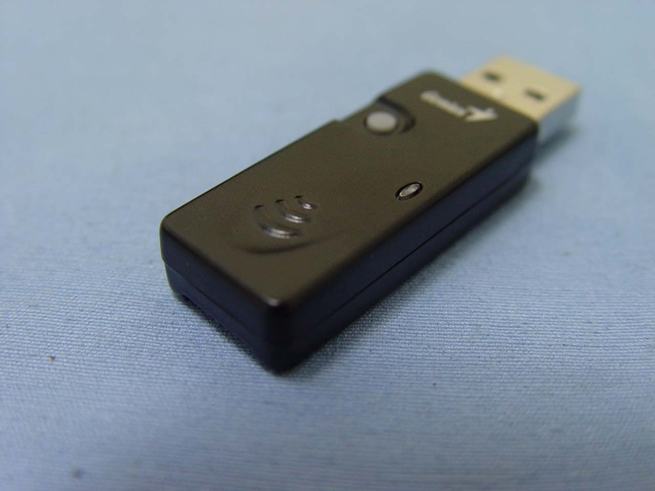
Click to zoom
Application Details
- Equipment Class
- DXX - Part 15 Low Power Communication Device Transmitter
- Date of Grant
- Nov 13, 2006
- Application Purpose
- Original Equipment
- Date of Application
- Nov 13, 2006
- Equipment Note
- Navigator 805
- Frequency Range
- 2402.00000000 - 2480.00000000
- Company
- KYE SYSTEMS CORP.
- Country
- Taiwan
Documents & Files
Document Text
Text extracted from the exhibit documents filed with the FCC. Open a document above to read the original.
Users Manual
ENGLISH 1 Hardware Installation 1. You can connect the receiver to a USB port of a PC 2. Install two AA batteries in the mouse. 3. Turn on your computer. The mouse can be worked. Not˸ˍʳIf the mouse does not have connection to the receiver, press the button on the receiver first and then press the button under the mouse for channel setting again. Important: Remember do not put the batteries in the wrong direction; use the same types of batteries. Also, keep all drinks away! If any spill occurs on the receiver, unplug the USB connector first and clean the receiver immediately. Please switch the button to "off" under the mouse once you don't use it for a long time, and remove the batteries if you do not use this device for at least two weeks. W arning: (Troubleshooting) 1. Please do not use wireless laser mouse on a desk, which is made of glass or mirror. Also, a flat surface is necessary or the laser sensor will error easily. When you use wireless laser mouse on a desk that is made of metal, try using a pad and reduce the receiving distance. 2. The wireless laser mouse channel provides 16 channels and 256 ID-codes, and it automatically selects the ID # for your mouse. You can only set up one wireless laser mouse at a time. ENGLISH 2 3. If the power indicator is on (see Button Assignments), then the batteries have lost their charge, so you need to replace them. Software Installation 1.Make sure the mouse is connected to the computer. 2.Put the CD driver into the CD drive. 3.Follow the instructions on the screen to finish the software installation. Security Function Setting: 1. After you install software driver, please click the mouse icon on the task bar and select “Mouse”. 2. Click “Settings” when the Mouse Properties appears up and click “Security Options”. 3. Choose a picture from your images to display when the computer is locked. Also set your password for unlock computer. Then, press “OK”, and the security setting will be finished. ENGLISH 3 4. If you want to start the security function, just press “ ”, and the picture you set pop up to hide the screen. For security, the mouse and keyboard won’t work. 5. If you want to unlock this function, just press “ ”again, and install your password. Factory Setting ENGLISH 4 Button Assignments 1. Left Button: Provides traditional mouse functions like click, double click and drag. 2. Right Button: You can assign this button to frequently used keyboard and mouse functions in addition to features like Easy Jump, Auto-Panning, Zoom, etc. 3. Magic-Roller: Press the “Magic-Roller” to surf the Internet and Windows documents. Horizontal Scroll: Press the roller to the left and the cursor scrolls to the left; press the roller to the right and the cursor scrolls to the right. 4. Security: Lock your screen, mouse and keyboard unless you install the password. 5. Power indicator: If your battery power is low, the LED will brighten. This device complies with part 15 of the FCC rules. Operation is subject to the following two conditions. (1)This device may not cause harmful interference, and (2)This device must accept any interference received, including interference that may cause undesired operation. Per FCC 15.21, you are cautioned that changes or modifications not expressly approved by the part responsible for compliance could void the user’s authority to operate the equipment. FCC RF Radiation Exposure Statement: This equipment complies with FCC RF radiation exposure limits set forth for an uncontrolled environment. This device and its antenna must not be co-located or operating in conjunction with any other antenna or transmitter. This equipment has been tested and found to comply with the limits for a class B digital device, pursuant to part 15 of the FCC Rules. These limits are designed to provide reasonable protection against harmful interference in a residential installation.This equipment generates, uses and can radiate radio frequency energy and, if not installed and used in accordance with the instructions, may cause harmful interference to radio communications. However, there is no guarantee that interference will not occur in a particular installation. If this equipment does cause harmful interference to radio or television reception, which can be determined by turning the equipment off and on, the user is encouraged to try to correct the interference by one or more of the following measures:---Reorient or relocate the receiving antenna.---Increase the separation between the equipment and receiver.---Connect the equipment into an outlet on a circuit different from that to which the receiver is connected.---Consult the dealer or an experienced radio/TV technician for help. 4
Cover Letter(s)
KYE KYE FSUGMZHK
External Photos
Compliance Certification Services Inc. Report No: 60607208 Date of Issue: November 6, 2006 Page 1 Total Page: 3 Rev. 00 EXTERNAL PHOTOGRAPHS OF EUT
Internal Photos
Compliance Certification Services Inc. Report No: 60607208 Date of Issue: November 6, 2006 Page 2 Rev.00 INTERNAL PHOTOGRAPHS OF EUT Compliance Certification Services Inc. Report No: 60607208 Date of Issue: November 6, 2006 Page 3 Rev.00
Test Report
Compliance Certification Services Inc. Report No.: 60607208-RP1 FCC ID: FSUGMZHK Date of Issue: November 6, 2006 Note: This report shall not be reproduced except in full, without the written approval of Compliance Certification Services Inc. This document may be altered or revised by Compliance Certification Services Inc. personnel only, and shall be noted in the revision section of the document. Page 1 Total Page: 27 Rev. 00 FCC 47 CFR PART 15 Subpart C TEST REPORT For Navigator 805 Model Number: GM-050024 / R Tr a d e Na me : G e n ius Issued to KYE SYSTEMS CORP. No.492, Sec.5, Chung Hsin Rd., San Chung, Taipei Hsien, 241, Taiwan, R.O.C. Issued by Compliance Certification Services Inc. No. 81-1, Lane 210, Bade Rd. 2, Luchu Hsiang, Taoyuan Hsien, (338) Taiwan, R.O.C. http://www.ccsemc.com.tw [email protected] Compliance Certification Services Inc. Report No.: 60607208-RP1 FCC ID: FSUGMZHK Date of Issue: November 6, 2006 Page 2 Rev. 00 TABLE OF CONTENTS 1. TEST RESULT CERTIFICATION................................................................................................. 3 2. EUT DESCRIPTION....................................................................................................................... 4 3. TEST METHODOLOGY................................................................................................................ 5 3.1 EUT CONFIGURATION................................................................................................................. 5 3.2 EUT EXERCISE............................................................................................................................. 5 3.3 GENERAL TEST PROCEDURES...................................................................................................... 5 3.4 FCC PART 15.205 RESTRICTED BANDS OF OPERATIONS................................................. 6 3.5 DESCRIPTION OF TEST MODES.................................................................................................... 6 4. INSTRUMENT CALIBRATION.................................................................................................... 7 4.1 MEASURING INSTRUMENT CALIBRATION............................................................................... 7 4.2 MEASUREMENT EQUIPMENT USED.................................................................................. 7 4.3 FACILITIES .................................................................................................................................. 8 4.4 EQUIPMENT................................................................................................................................. 8 4.5 TABLE OF ACCREDITATIONS AND LISTINGS................................................................................ 9 5. SETUP OF EQUIPMENT UNDER TEST.................................................................................... 10 5.1 SETUP CONFIGURATION OF EUT................................................................................................ 10 5.2 SUPPORT EQUIPMENT ........................................................................................................ 10 6. FCC PART 15.249 REQUIREMENTS......................................................................................... 11 6.1 BAND EDGES MEASUREMENT ......................................................................................... 11 6.2 RADIATED EMISSION ......................................................................................................... 16 6.3 POWERLINE CONDUCTED EMISSIONS........................................................................... 23 APPENDIX 1 PHOTOGRAPHS OF TEST SETUP............................................................................ 26 Compliance Certification Services Inc. Report No.: 60607208-RP1 FCC ID: FSUGMZHK Date of Issue: November 6, 2006 Page 4 Rev. 00 2. EUT DESCRIPTION Product Navigator 805 Trade Name Genius Model Number GM-050024 / R Model Discrepancy N/A Power Supply Vdc from USB Port of Host PC Modulation Technique GFSK Number of Channels 16 Channels Channel Frequency (MHz) 0 2402 1 2425 2 2448 3 2471 4 2405 5 2428 6 2451 7 2474 8 2408 9 2431 10 2454 11 2477 12 2411 13 2434 14 2457 15 2480 Antenna Gain -3dBi Antenna Designation Printed Antenna Remark: 1. The sample selected for test was engineering sample that approximated to production product and was provided by manufacturer. 2. This submittal(s) (test report) is intended for FCC ID: FSUGMZHK filing to comply with Section 15.10, 15.109 ,15.207, 15.209, 15.249 (FCC Part 15, Subpart C Rules.) Compliance Certification Services Inc. Report No.: 60607208-RP1 FCC ID: FSUGMZHK Date of Issue: November 6, 2006 Page 5 Rev. 00 3. TEST METHODOLOGY The tests documented in this report were performed in accordance with ANSI C63.4 and FCC CFR 47 2.1046, 2.1047, 2.1049, 2.1051, 2.1053, 2.1055, 2.1057, 15.207, 15.209 and 15.249. 3.1 EUT CONFIGURATION The EUT configuration for testing is installed on RF field strength measurement to meet the Commissions requirement and operating in a manner that intends to maximize its emission characteristics in a continuous normal application. 3.2 EUT EXERCISE The EUT was operated in the engineering mode to fix the TX frequency that was for the purpose of the measurements. According to its specifications, the EUT must comply with the requirements of the Section 15.107 and 15.109 under the FCC Rules Part 15 Subpart B and Section 15.207, 15.209,15.249 under the FCC Rules Part 15 Subpart C. 3.3 GENERAL TEST PROCEDURES Conducted Emissions The EUT is placed on the turntable, which is 0.8 m above ground plane. According to the requirements in Section 13.1.4.1 of ANSI C63.4 Conducted emissions from the EUT measured in the frequency range between 0.15 MHz and 30MHz using CISPR Quasi-peak and average detector modes. Radiated Emissions The EUT is placed on a turn table, which is 0.8 m above ground plane. The turntable shall rotate 360 degr…
Text truncated - open the document above for the full version.
Test Setup Photos
Compliance Certification Services Inc. Report No.: 60607208-RP1 FCC ID: FSUGMZHK Date of Issue: November 6, 2006 Page 26 Rev. 00 APPENDIX 1 PHOTOGRAPHS OF TEST SETUP Radiated Emission Set up Photos Compliance Certification Services Inc. Report No.: 60607208-RP1 FCC ID: FSUGMZHK Date of Issue: November 6, 2006 Page 27 Rev. 00 Powerline Conducted Emissions Setup Photos
Contact Information
Applicant
Ricky Chen(Section Supervisor)
Test Firm
Compliance Certification Services Inc.Harris Lai
Technical Specifications
| # | Rule Parts | Frequency Range | Power Output |
|---|---|---|---|
| 1 | 15C | 2.40 GHz - 2.48 GHz | - |
Other Applications from KYE SYSTEMS CORP.
FSUGG0AM
Aug 20, 2026Wireless Speaker
Equipment Class
DSS - Part 15 Spread Spectrum Transmitter
FSUGKZI2
May 23, 2026Wireless Keyboard
Equipment Class
DXX - Part 15 Low Power Communication Device TransmitterFSUGMZN6
Apr 20, 2026Wireless Mouse
Equipment Class
DTS - Digital Transmission SystemFSUGMZN4
Apr 03, 2026Wireless Mouse
Equipment Class
DXX - Part 15 Low Power Communication Device TransmitterFSUGMZN7
Apr 01, 2026Wireless Mouse
Equipment Class
DTS - Digital Transmission System