FSUGMZHYErgo 825 Laser - Wireless Mouse
KYE SYSTEMS CORP.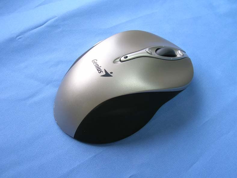
Click to zoom
Application Details
- Equipment Class
- DXX - Part 15 Low Power Communication Device Transmitter
- Date of Grant
- Jun 11, 2007
- Application Purpose
- Original Equipment
- Date of Application
- Jun 10, 2007
- Equipment Note
- Ergo 825 Laser - Wireless Mouse
- Frequency Range
- 2402.00000000 - 2480.00000000
- Company
- KYE SYSTEMS CORP.
- Country
- Taiwan
Documents & Files
Document Text
Text extracted from the exhibit documents filed with the FCC. Open a document above to read the original.
Users Manual
ENGLISH 1 Hardware Installation 1. You can connect the receiver to a USB port of a PC or Notebook. 2. Install the enclosed two AA batteries as directed 3. Turn on your computer 4. The channel setting is factory preset. Please try on the mouse after complete above procedures; if it is not working; Please re-connect by pressing the button on the receiver first and observe for flash light and press connect button underneath the mouse , then receiver will be lit and off when connection is confirmed. Software Installation 1. Make sure the mouse is connected to the computer 2. Place the setup disk (CD driver) into a DVD/CD Rom drive 3. Follow the instruction on the screen to complete the software installation ENGLISH 2 Warning (Trouble shooting) 1. Please do not use the wireless laser out on a desk that is made of glass or mirror 2. Although that the mouse has granted the eye safety certification, it is strongly suggested that a direct eye contact with the laser lens should be avoid. 3. The wireless laser mouser gives you free movement and an enjoyable wireless experience. For Optimal performance, place the receiver at least 8 inches (20cm) away from the mouse device. 4. For “HELP: of the Genius driver, please double click the icon right hand side. Mouse button definition: 1. Smart-search button Using the mouse to mark “key words” and press the button for fast access to open Yahoo, Google webpage or your PC system(Yahoo is the default webpage, you can change it in ioCentre software). All the information or files you searched will be listed. 2. Flip 3D button Provides fast access to scan all open windows in one easy view. 3. Zoom in/out button Press this button, then scroll the middle button. Scrolling up is “Zoom-in” and scrolling down is “Zoom-out”. Press the button again to release the function. ENGLISH 3 4. Left Button Provides traditional mouse functions such as click, double click and drag. 5. Turbo roller button Provides quick roller- up 6. Roller button/Middle button Scroll the button to surf the Internet and Windows documents. 7. Right button Provides traditional mouse click function 8. Turbo roller button Provides quick roller down 9. Battery low indicator The LED will be lit /flash when battery power is low. ENGLISH 4 10. FCC Notices FEDERAL COMMUNICATIONS COMMISSION INTERFERENCE STATEMENT This equipment has been tested and found to comply with the limits for a Class B digital device, pursuant to Part 15 of the FCC Rules. These limits are designed to provide reasonable protection against harmful interference in a residential installation. This equipment generates, uses and can radiate radio frequency energy and, if not installed and used in accordance with the instructions, may cause harmful interference to radio communications. However, there is no guarantee that interference will not occur in a particular installation. If this equipment does cause harmful interference to radio or television reception, which can be determined by turning the equipment off and on, the user is encouraged to try to correct the interference by one or more of the following measures: --Reorient or relocate the receiving antenna. --Increase the separation between the equipment and receiver. --Connect the equipment into an outlet on a circuit different from that to which the receiver is connected. --Consult the dealer or an experienced radio/TV technician for help. This device complies with Part 15 of the FCC Rules. Operation is subject to the following two conditions: (1) This device may not cause harmful interference (2) This device must accept any interference received, including interference that may cause undesired operation. CAUTION: Change or modification not expressly approved by the party responsible for compliance could void the user’s authority to operate this equipment.
Cover Letter(s)
(GM-07007-T)Confidentiality.jpg
External Photos
Report No:074L150-RFUSP07V01-A Page: 41 of 51 Version:1.0 Attachement ¾ EUT Photograph (1) EUT Photo (2) EUT Photo
ID Label/Location Info
FCC ID Label The FCC ID Label will be placed on the equipment as shown in the photograph below. Ergo 825 Laser Model No.: GM-070007/T F F C C C C I I D D : : FSUGMZHY This device complies with Part 15 of the FCC Rules. Operation is subject to the following two conditions: (1) this device may not cause harmful interference and (2) this device must accept any interference received, including interference that may cause undesired operation. S/N: Made in Taiwan
Internal Photos
Report No:074L150-RFUSP07V01-A Page: 42 of 51 Version:1.0 (3) EUT Photo (4) EUT Photo Report No:074L150-RFUSP07V01-A Page: 43 of 51 Version:1.0 (5) EUT Photo (6) EUT Photo Report No:074L150-RFUSP07V01-A Page: 44 of 51 Version:1.0 (7) EUT Photo (8) EUT Photo Report No:074L150-RFUSP07V01-A Page: 45 of 51 Version:1.0 (9) EUT Photo (10) EUT Photo Report No:074L150-RFUSP07V01-A Page: 46 of 51 Version:1.0 (11) EUT Photo (12) EUT Photo Report No:074L150-RFUSP07V01-A Page: 47 of 51 Version:1.0 (13) EUT Photo (14) EUT Photo Report No:074L150-RFUSP07V01-A Page: 48 of 51 Version:1.0 (15) EUT Photo Report No:074L150-RFUSP07V01-A Page: 49 of 51 Version:1.0 (16) EUT Photo Report No:074L150-RFUSP07V01-A Page: 50 of 51 Version:1.0 (17) EUT Photo (18) EUT Photo Report No:074L150-RFUSP07V01-A Page: 51 of 51 Version:1.0 (19) EUT Photo (20) EUT Photo
Operational Description
Report No:074L150-RFUSP07V01-A Page: 5 of 51 Version:1.0 1.2. Operational Description The EUT is 2.4GHz Wireless Mouse. The operation frequency is from 2400 MHz to 2483.5MHz with GFSK modulation. The signal will be transmitted through 2.4 GHz RF signal from the Printed on PCB antenna from EUT to receiver. DC 3V shall be provided for EUT operation.
Test Report
Report No:074L150-RFUSP07V01-A Page: 1 of 51 Version:1.0 Test Report Product Name:Ergo 825 Laser Model No. :GM-070007/T FCC ID. :FSUGMZHY Applicant :KYE SYSTEMS CORP. (Genius) Address :No. 492, Sec. 5, Chung Hsin Rd., San Chung, Taipei Hsien, 24160, Taiwan, R. O. C. Date of Receipt:2007/04/14 Issued Date :2007/05/16 Report No. :074L150-RFUSP07V01-A The test results relate only to the samples tested. The test report shall not be reproduced except in full without the written approval of QuieTek Corporation. Report No:074L150-RFUSP07V01-A Page: 2 of 51 Version:1.0 Test Report Certification Issued Date : 2007/05/16 Report No. : 074L150-RFUSP07V01-A Product Name : Ergo 825 Laser Applicant : KYE SYSTEMS CORP. (Genius) Address : No. 492, Sec. 5, Chung Hsin Rd., San Chung, Taipei Hsien, 24160, Taiwan, R. O. C. Manufacturer : KYE SYSTEMS CORP. (Genius) Model No. : GM-070007/T FCC ID. : FSUGMZHY Rated Voltage : AC 120 V / 60 Hz EUT Voltage : DC 3V (Power by Battery) Trade Name : Genius Applicable Standard : FCC CFR Title 47 Part 15 Subpart C Section 15.249: 2006 Test Result : Complied The test results relate only to the samples tested. The test report shall not be reproduced except in full without the written approval of QuieTek Corporation. Documented By : ( Carol Tsai ) Tested By : (Sheena Huang ) Approved By : ( Roy Wan ) Report No:074L150-RFUSP07V01-A Page: 3 of 51 Version:1.0 TABLE OF CONTENTS Description Page 1. General Information ..................................................................................................... 4 1.1. EUT Description ............................................................................................................. 4 1.2. Operational Description .................................................................................................. 5 1.3. Test Mode .......................................................................................................................6 1.4. Tested System Details .................................................................................................... 7 1.5. Configuration of tested System ...................................................................................... 7 1.6. EUT Exercise Software .................................................................................................. 8 1.7. Test Facility..................................................................................................................... 9 2. Conducted Emission.................................................................................................. 10 2.1. Test Equipment............................................................................................................. 10 2.2. Test Setup .................................................................................................................... 10 2.3. Limits ............................................................................................................................ 11 2.4. Test Procedure ............................................................................................................. 11 2.5. Test Specification.......................................................................................................... 11 2.6. Uncertainty ................................................................................................................... 11 2.7. Test Result....................................................................................................................12 3. Radiated Emission ..................................................................................................... 13 3.1. Test Equipment............................................................................................................. 13 3.2. Test Setup .................................................................................................................... 13 3.3. Limits ............................................................................................................................ 14 3.4. Test Procedure ............................................................................................................. 15 3.5. Test Specification.......................................................................................................... 15 3.6. Uncertainty ................................................................................................................... 15 3.7. Test Result....................................................................................................................16 3.8. Test Photo .................................................................................................................... 32 4. Band Edge................................................................................................................... 34 4.1. Test Equipment............................................................................................................. 34 4.2. Test Setup .................................................................................................................... 35 4.3. Limits ............................................................................................................................ 36 4.4. Test Procedure ............................................................................................................. 36 4.5. Test Specification.......................................................................................................... 36 4.6. Uncertainty ................................................................................................................... 36 4.7. Test Result....................................................................................................................37 Attachement ......................................................................................................................................... 41 EUT Photograph......…
Text truncated - open the document above for the full version.
Test Setup Photos
Report No:074L150-RFUSP07V01-A Page: 32 of 51 Version:1.0 3.8. Test Photo Test Mode : Mode 1: Transmitter Description: Front View of Radiated Emission Test Setup Test Mode : Mode 1: Transmitter Description: Back View of Radiated Emission Test Setup Report No:074L150-RFUSP07V01-A Page: 33 of 51 Version:1.0 Test Mode : Mode 1: Transmitter Description: Front View of Radiated Emission Test Setup (Horn)
Contact Information
Applicant
Ricky Chen(Section Supervisor)
Test Firm
DEKRA Testing and Certification Co., Ltd.Sky Hsu
Technical Specifications
| # | Rule Parts | Frequency Range | Power Output |
|---|---|---|---|
| 1 | 15C | 2.40 GHz - 2.48 GHz | - |
Other Applications from KYE SYSTEMS CORP.
FSUGG0AM
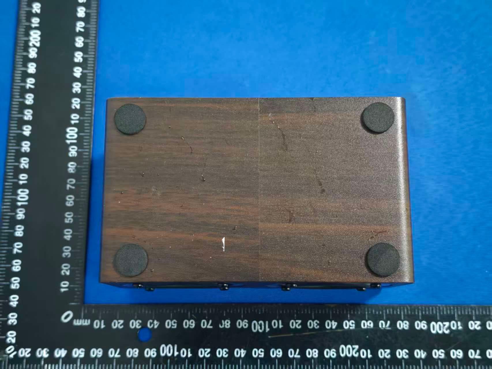
Aug 20, 2026Wireless Speaker
Equipment Class
DSS - Part 15 Spread Spectrum Transmitter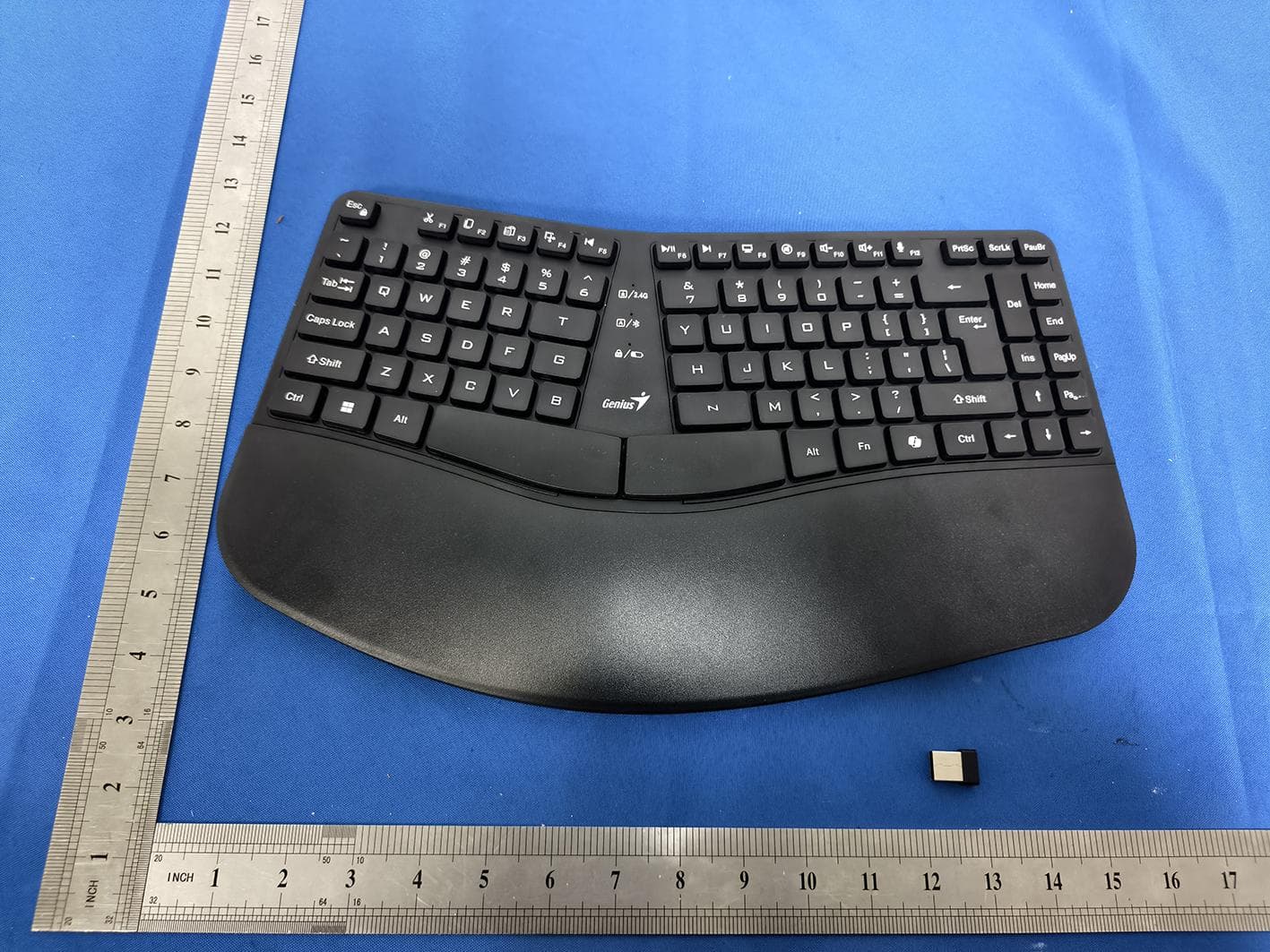
FSUGKZI2
May 23, 2026Wireless Keyboard
Equipment Class
DXX - Part 15 Low Power Communication Device TransmitterFSUGMZN6
Apr 20, 2026Wireless Mouse
Equipment Class
DTS - Digital Transmission SystemFSUGMZN4
Apr 03, 2026Wireless Mouse
Equipment Class
DXX - Part 15 Low Power Communication Device TransmitterFSUGMZN7
Apr 01, 2026Wireless Mouse
Equipment Class
DTS - Digital Transmission System