FSUGMZIYWireless mouse for PCs
KYE SYSTEMS CORP.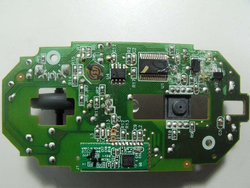
Click to zoom
Application Details
- Equipment Class
- DXX - Part 15 Low Power Communication Device Transmitter
- Date of Grant
- Nov 14, 2009
- Application Purpose
- Original Equipment
- Date of Application
- Nov 14, 2009
- Equipment Note
- Wireless mouse for PCs
- Frequency Range
- 2402.00000000 - 2480.00000000
- Company
- KYE SYSTEMS CORP.
- Country
- Taiwan
Documents & Files
Document Text
Text extracted from the exhibit documents filed with the FCC. Open a document above to read the original.
Users Manual
English 1 Hardware Installation Note: Supports Windows 7/Vista/XP/2000 1. You can connect the receiver to a USB port of a PC. 2. Install two AA batteries in the mouse. 3. Turn on your computer. The mouse can now work. Warning: (Troubleshooting) 1. Do not use the wireless optical/laser mouse on a desk which is made of glass or mirror. 2. The connection of the wireless device is factory preset, so when you plug the USB receiver into any USB port, the connection between the micro receiver and the mouse will be established automatically. English 2 3. If you feel the mouse does not move smooth as usual, it is possible the batteries have lost their charge so you need to replace them. Remember to put the batteries in the correct direction. 4. In case your mouse connection has been accidentally lost, a ‘Binding File” is available on the Genius website. Go to www.genisunet.com, select “Service & Support”, “Drivers” to down load the driver, and double click on the file for the product you purchased, and the wireless connection will be re-established. Mouse Button Assignments 1. Left Button: Provides traditional mouse functions like click, double click and drag. 2. Right Button: Provides traditional mouse click function 3. Magic-Roller: Scroll the button to surf the Internet and Windows documents. 4. Turbo scroll button: Provides quick roller up. 5. Turbo scroll button: Provides quick roller down. Note: Changes or modifications not expressly approved by the party responsible for compliance could void the user's authority to operate the equipment. (15.21) This device complies with part 15 of the FCC Rules. Operation is subject to the following two conditions: (1) This device may not cause harmful interference, and (2) this device must accept any interference received, including interference that may cause undesired operation.(15.19(a)(3)) 3
ID Label/Location Info
Label location
Internal Photos
Global Certification Corp. PHOTO OF EUT PHOTOS OF EUT Global Certification Corp. Report No. : 980403 PHOTO OF EUT PHOTO OF EUT : 1 of 3 Front View of EUT Rear View of EUT Global Certification Corp. Report No. : 980403 PHOTO OF EUT PHOTO OF EUT : 2 of 3 Inside View of EUT Inside View of EUT Global Certification Corp. Report No. : 980403 PHOTO OF EUT PHOTO OF EUT : 3 of 3 Component Side of Main Board Solder Side of Main Board
Test Report
Global Certification Corp. Date of Issue: Nov. 03,2009 Report No: F980403A Page1/25 FCC 47 CFR PART 15 SUBPART C TEST REPORT FOR Product Name: Navigator 820 Model : GM-080023/T Trade Name: Genius Issued to KYE SYSTEMS CORP. No.492,Sec.5, Chung Hsin Rd., San Chung, Taipei Hsien, 24160, Taiwan, R.O.C. Issued by Global Certification Corp. EMI Test Site Sansia Lab NO.34-3,Zihhe Rd.,Sansia Township,Taipei County 237, Taiwan ,R.O.C. EMC Test Site Sijhih office and Lab No. 146. Sec.2. Siangjhang Rd. Sijhih City. Taipei County 221, Taiwan(R.O.C.) Note: This test refers exclusively to the test presented test model and sample. This report shall not be reproduced except in full, without the written approval of Global Certification Corporation. This document may be altered or revised by Global Certification Corporation. Personnel only, and shall be noted in the revision section of the document. Global Certification Corp. Date of Issue: Nov. 03,2009 Report No: F980403A Page2/25 TABLE OF CONTENTS ----------------------------------------------------------------------------------------------------- 2 1. GENERAL INFORMATION -------------------------------------------------------------------------------------------------------- 3 1.1 DESCRIPTION OF THE TESTED SAMPLES------------------------------------------------------------------------------------------------ 4 2. TEST METHODOLOGY ------------------------------------------------------------------------------------------------------------- 5 2.1 GENERAL TEST PROCEDURES --------------------------------------------------------------------------------------------------- 5 2.2 FCC PART 15.205 RESTRICTED BANDS OF OPERATIONS ----------------------------------------------------------------- 5 2.3 DESCRIPTION OF TEST MODES -------------------------------------------------------------------------------------------------- 6 2.4 DESCRIPTION OF THE SUPPORT EQUIPMENTS ----------------------------------------------------------------------------- 7 3. TEST AND MEASUREMENT EQUIPMENT ----------------------------------------------------------------------------------- 9 3.1 CALIBRATION----------------------------------------------------------------------------------------------------------------------- 9 3.2 EQUIPMENT-------------------------------------------------------------------------------------------------------------------------- 9 4. SECTION 15.249 REQUIREMENTS (FUNDAMENTAL/ HARMONICS) ----------------------------------------------11 4.1 TEST SETUP------------------------------------------------------------------------------------------------------------------------11 4.2 LIMIT-------------------------------------------------------------------------------------------------------------------------------11 4.3 RESULT: PASSED---------------------------------------------------------------------------------------------------------------11 4.4 TEST DATA: ------------------------------------------------------------------------------------------------------------------------11 5. SECTION 15.205 REQUIREMENTS (BAND EDGE) -------------------------------------------------------------------------15 5.1 TEST SETUP------------------------------------------------------------------------------------------------------------------------15 5.2 LIMIT-------------------------------------------------------------------------------------------------------------------------------15 5.3 RESULT: PASSED---------------------------------------------------------------------------------------------------------------16 5.4 TEST DATA: ------------------------------------------------------------------------------------------------------------------------16 6. SECTION 15.209 REQUIREMENTS (GENERAL RADIATED EMISSION) -------------------------------------------21 6.1 TEST SETUP------------------------------------------------------------------------------------------------------------------------21 6.2 LIMIT-------------------------------------------------------------------------------------------------------------------------------22 6.3 TEST PROCEDURE-----------------------------------------------------------------------------------------------------------------22 6.4 RESULT: PASSED-----------------------------------------------------------------------------------------------------------------22 6.5 TEST DATA: ------------------------------------------------------------------------------------------------------------------------23 7. SECTION 15.207 REQUIREMENTS (POWERLINE CONDUCTED EMISSIONS)-----------------------------------25 APPENDIX 1 PHOTOS OF TEST CONFIGURATION APPENDIX 3 PHOTOS OF EUT Global Certification Corp. Date of Issue: Nov. 03,2009 Report No: F980403A Page3/25 1. GENERAL INFORMATION Applicant : KYE SYSTEMS CORP. Address : No.492,Sec.5, Chung Hsin Rd., San Chung, Taipei Hsien, 24160, Taiwan, R.O.C. Manufacturer : KYE SYSTEMS CORP. Address : No.492,Sec.5, Chung Hsin Rd., San Chung, Taipei Hsien, 24160, Taiwan, R.O.C. EUT : Navigator 820 Model Name : GM-080023/T Model Differences : N/A Is here with confirmed to comply with the requirements set out in the FCC Rules and Regulations Part 15 Subpart C and the measurement procedures were according to ANSI C63.4-2003. The said equipment in the configuration described in this report shows the maximum emission levels emanating from equipment are within the compliance requirements. FCC part 15 subpart C Receipt Date : 08/04/2009 Final Test Date : 11/03/2009 Taipei, Taiwan Nov. 03,2009 Alex Chou / Manager (Place) (Date) (Signature) Designation Number: TW1030 Global Certification Corp. Date of Issue: Nov. 03,2009 Report No: F980403A Page4/25 1.1 DESCRIPTION OF THE TESTED SAMPLES EUT Name : Navigator 820 Model Number : GM-080023/T FCC ID : FSUGMZIY Input Voltage : 3Vdc Power From Inside Outside Adaptor BATTERY AC Power Source DC Power Source Support Unit PC Operate Frequency : Refer to the channel list as described below Modulation Technique : G…
Text truncated - open the document above for the full version.
Test Setup Photos
Global Certification Corp. Appendix 1 PHOTOS OF TEST CONFIGURATION Global Certification Corp. Report No. : F980403A Appendix 1 : 1 of 1
Contact Information
Applicant
Ricky Chen(Section Supervisor)
Test Firm
Global Certification Corp.Alex Chou
Technical Specifications
| # | Rule Parts | Frequency Range | Power Output |
|---|---|---|---|
| 1 | 15C | 2.40 GHz - 2.48 GHz | - |
Other Applications from KYE SYSTEMS CORP.
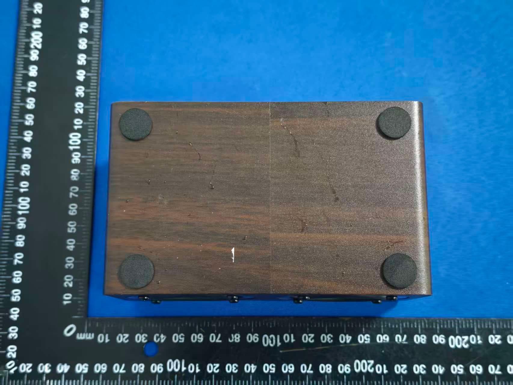
FSUGG0AM
Aug 20, 2026Wireless Speaker
Equipment Class
DSS - Part 15 Spread Spectrum Transmitter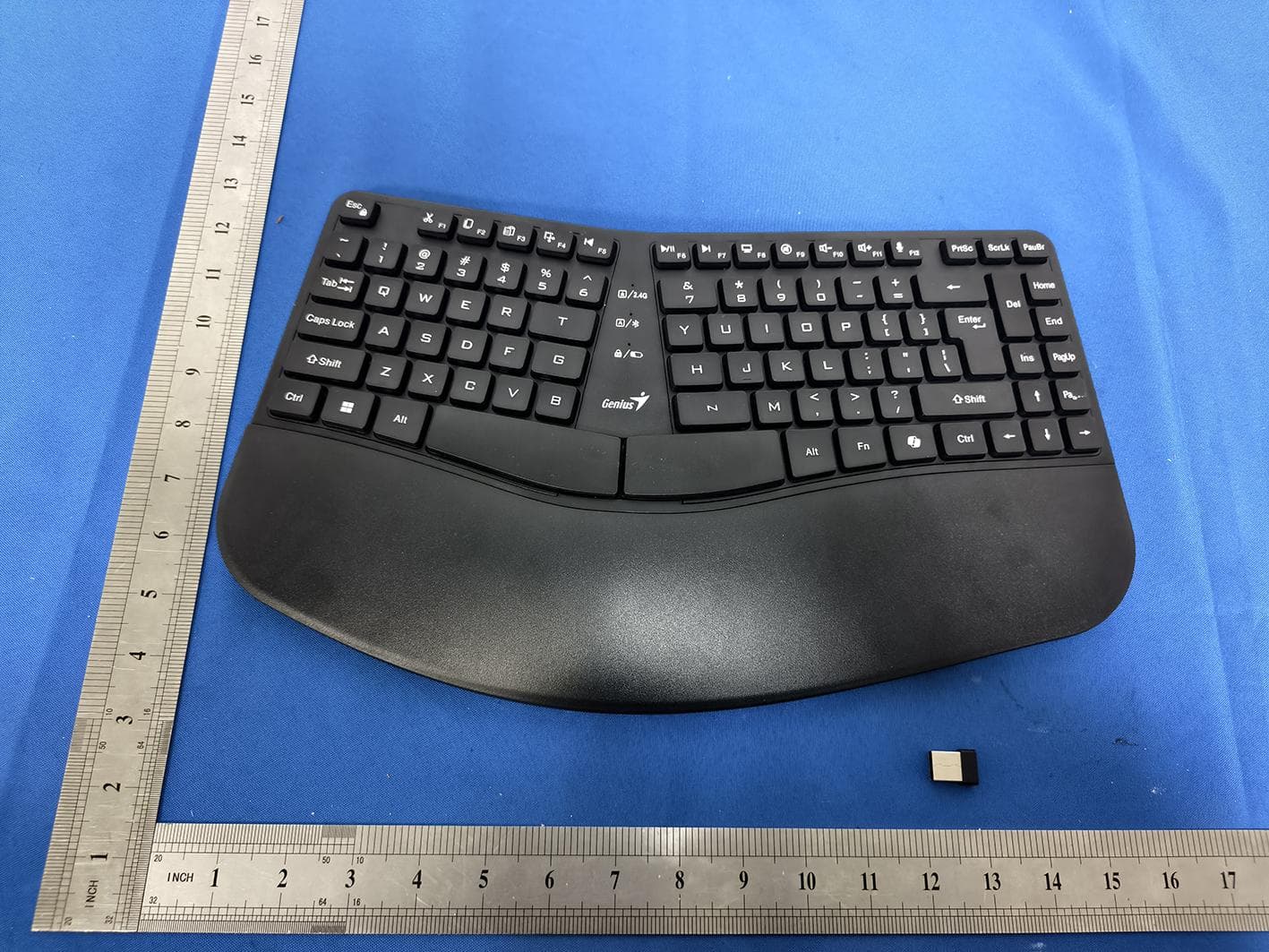
FSUGKZI2
May 23, 2026Wireless Keyboard
Equipment Class
DXX - Part 15 Low Power Communication Device TransmitterFSUGMZN6
Apr 20, 2026Wireless Mouse
Equipment Class
DTS - Digital Transmission SystemFSUGMZN4
Apr 03, 2026Wireless Mouse
Equipment Class
DXX - Part 15 Low Power Communication Device TransmitterFSUGMZN7
Apr 01, 2026Wireless Mouse
Equipment Class
DTS - Digital Transmission System