FCCID.CO- FCC ID Database
HomeCompaniesEquipment ClassesSearch

Β© 2026 FCC ID Database. All rights reserved.

AboutContactData sourced from FCC public records
  1. Home/
  2. Biolase, Inc./
  3. G2OEPIC

G2OEPICEPIC 10 Dental Soft Tissue Laser

Biolase, Inc.
EPIC 10 Dental Soft Tissue Laser - FCC ID G2OEPIC - Biolase, Inc.
Click to zoom

Application Details

Equipment Class
DTS - Digital Transmission System
Date of Grant
Jul 02, 2012
Application Purpose
Original Equipment
Date of Application
Jul 02, 2012
Equipment Note
EPIC 10 Dental Soft Tissue Laser
Frequency Range
2425.00000000 - 2475.00000000
Company
Biolase, Inc.
Country
United States

Documents & Files

Select a file to view

Users Manual

β†—

Cover Letter(s)

β†—
β†—

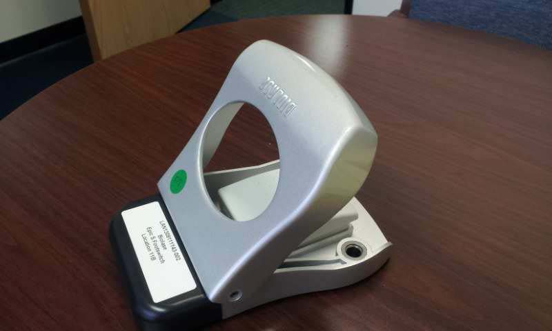
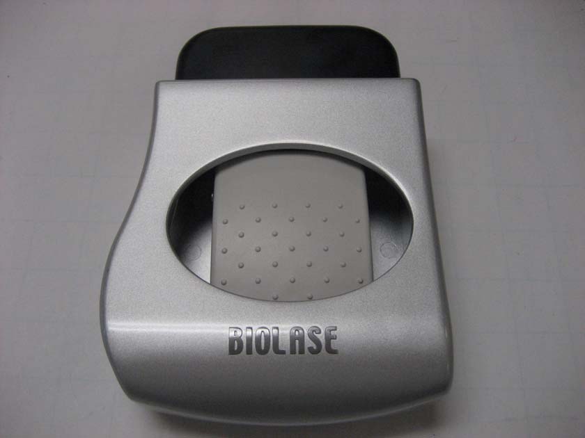
External Photos

β†—
β†—

ID Label/Location Info

β†—
β†—

Internal Photos

β†—
β†—

Test Report

β†—

Test Setup Photos

β†—

Document Text

Text extracted from the exhibit documents filed with the FCC. Open a document above to read the original.

Users Manual

User Manual 2 | Page 5400321Rev. X: DRAFT Contents Introduction......................................................................................................... 4 Section 1: Installation ....................................................................................... 5 Installation Instructions .................................................................................................. 5 Facility Requirements .................................................................................................... 5 Electrical Supply ........................................................................................................ 5 Environmental Requirements .................................................................................... 5 Section 2: Safety................................................................................................ 6 Precautions....................................................................................................................6 Safety Instructions ......................................................................................................... 6 Safety Features ............................................................................................................. 7 Energy Monitor........................................................................................................... 7 System Monitor .......................................................................................................... 7 Power Switch ............................................................................................................. 7 Access Key Code....................................................................................................... 8 CONTROL Button ...................................................................................................... 8 Wireless Footswitch ................................................................................................... 8 Remote Interlock........................................................................................................ 8 Emergency Stop ........................................................................................................ 9 Functional Display...................................................................................................... 9 Safety Classification ...................................................................................................... 9 Section 3: Equipment Description ................................................................. 10 General ........................................................................................................................10 Base Console .............................................................................................................. 10 Control Panel ............................................................................................................... 10 Main Menu and Procedures Screen ............................................................................ 11 Re-usable Surgical Delivery System ........................................................................... 13 Fiber Optic Connection ................................................................................................ 13 Single Use Tips............................................................................................................ 14 Surgical Handpiece Assembly ..................................................................................... 14 Whitening/Contour Handpiece..................................................................................... 16 Deep Tissue Handpiece (Optional).............................................................................. 17 Classical β€œFeed-Through” Fiber Handpiece (Optional) ................................................ 18 3 | Page 5400321Rev. X: DRAFT Tip Initiation: Parameters and Procedures ................................................................. 20 Section 4: Operating Instructions .................................................................. 21 System Setup .............................................................................................................. 21 Operation ..................................................................................................................... 21 CONTROL Button .................................................................................................... 22 Entering READY/STANDBY Modes ........................................................................ 22 READY Mode........................................................................................................... 22 Wireless Footswitch ................................................................................................. 23 AVERAGE POWER Display .................................................................................... 23 PULSE Mode Selection ........................................................................................... 23 Operational Algorithm .............................................................................................. 24 PROCEDURES Button ............................................................................................ 25 SETTINGS Screen................................................................................................... 25 Turn the Unit OFF .................................................................................................... 25 Section 5: Specifications ................................................................................ 26 Section 6: Contraindications, Warnings and Precautions ........................... 27 Contraindications ......................................................................................................... 27 Warnings and Precautions............................................................…

Text truncated - open the document above for the full version.

ID Label/Location Info

ID Label Location Main Unit Foot Switch

Test Report

EMC Report for Biolase Technology, Inc. on the EPIC 10 File: 100618766MPK-009 Page 1 of 60 TEST REPORT Report Number: 100618766MPK-009 Project Number: G100618766 Report Date: April 30, 2012 Testing performed on the Dental Soft Tissue Laser Model Number: EPIC 10 FCC ID: G2OEPIC IC: 10338A-EPIC to FCC Part 15 Subpart C (15.247) RSS-210 Issue 8 FCC Part 15, Subpart B Industry Canada ICES-003 for Biolase Technology, Inc. Test Performed by: Test Authorized by: Intertek 1365 Adams Court Menlo Park, CA 94025 USA Biolase Technology, Inc. 4 Cromwell Irvine, CA 92618 USA Prepared by: Date: April 30, 2012 Krishna K Vemuri, Senior Staff Engineer Reviewed by: Date: April 30, 2012 Yuriy Litvinov, EMC Business Manager This report is for the exclusive use of Intertek's Client and is provided pursuant to the agreement between Intertek and its Client. Intertek's responsibility and liability are limited to the terms and conditions of the agreement. Intertek assumes no liability to any party, other than to the Client in accordance with the agreement, for any loss, expense or damage occasioned by the use of this report. Only the Client is authorized to copy or distribute this report and then only in its entirety. Any use of the Intertek name or one of its marks for the sale or advertisement of the tested material, product or service must first be approved in writing by Intertek. The observations and test results in this report are relevant only to the sample tested. This report by itself does not imply that the material, product, or service is or has ever been under an Intertek certification program. This report must not be used to claim product endorsement by A2LA, NIST nor any other agency of the U.S. Government. EMC Report for Biolase Technology, Inc. on the EPIC 10 File: 100618766MPK-009 Page 2 of 60 Report No. 100618766MPK-009 Equipment Under Test: Dental Soft Tissue Laser Trade Name: Biolase Technology, Inc. Model No.: EPIC 10 FCC ID: G2OEPIC IC: 10338A-EPIC Applicant: Biolase Technology, Inc. Contact: Mr. Peter Pham Address: 4 Cromwell Irvine, CA 92618 Country USA Tel. Number: (949) 361-1200 email [email protected] Applicable Regulation: FCC Part 15 Subpart C (15.247) RSS-210 Issue 8 FCC Part 15, Subpart B Industry Canada ICES-003 Test Site Location: ITS – Site 1 1365 Adams Drive Menlo Park, CA 94025 Date of Test: April 18 to April 30, 2012 We attest to the accuracy of this report: Krishna K Vemuri EMC Senior Staff Engineer Yuriy Litvinov EMC Business Manager EMC Report for Biolase Technology, Inc. on the EPIC 10 File: 100618766MPK-009 Page 3 of 60 TABLE OF CONTENTS 1.0 Introduction.................................................................................................................................... 4 1.1 Summary of Tests ...............................................................................................................5 2.0 General Description ....................................................................................................................... 6 2.1 Product Description ............................................................................................................6 2.2 Related Submittal(s) Grants ................................................................................................ 6 2.3 Test Methodology ...............................................................................................................7 2.4 Test Facility ........................................................................................................................ 7 3.0 System Test Configuration............................................................................................................ 8 3.1 Support Equipment ............................................................................................................. 8 3.2 Block Diagram of Test Setup.............................................................................................. 9 3.3 Justification ....................................................................................................................... 10 3.4 Software Exercise Program............................................................................................... 10 3.5 Mode of Operation During Test........................................................................................ 10 3.6 Modifications Required for Compliance .......................................................................... 10 4.0 Measurement Results................................................................................................................... 11 4.1 Conducted Output Power at Antenna Terminals .............................................................. 11 4.2 6-dB Bandwidth ................................................................................................................ 15 4.3 Out-of-Band Conducted Emissions .................................................................................. 19 4.4 Power Spectral Density..................................................................................................... 20 4.5 Transmitter Radiated Emissions ....................................................................................... 24 4.6 Radiated Emissions from Receiver and Digital Parts ....................................................... 46 4.7 AC Line Conducted Emission .......................................................................................... 53 5.0 RF Exposure Evaluation ............................................................................................................. 58 6.0 List of Test Equipment ................................................................................................................ 59 7.0 Document History ........................................................................................................................ 60 EMC Report for Biolase Technology, Inc. on the EPIC 10 File: 100618766MPK-009…

Text truncated - open the document above for the full version.

Test Setup Photos

Radiated Emissions Radiated Emissions AC Line Conducted Emissions

Contact Information

Applicant

Colleen Boswell(VP,RA/QA)
[email protected]949-226-8470Fax: 949-273-6688

Technical Contact

Intertek Testing Services NA, Inc.Krishna Vemuri
[email protected]650-463-2944

1365 Adams Court Β· Menlo Park, Utah Β· United States

Non-Technical Contact

Intertek Testing Services NA, Inc.Krishna Vemuri
[email protected]650-463-2944

Test Firm

Intertek Testing Services NA Inc.John Quigley
[email protected]949-448-4100Fax: 650-463-2910

Technical Specifications

#Rule PartsFrequency RangePower Output
115C2.42 GHz - 2.48 GHz200.00 Β΅W
Confidentiality
Long Term
Grant Notes
Power listed is EIRP. The antennas used for this transmitter must be installed to provide a separation distance of at least 20 cm from all persons and must not be co-located or operating in conjunction with any other antenna or transmitter not described in this application. End-users and installers must be provided with specific operating instructions for satisfying RF exposure compliance.

Other Applications from Biolase, Inc.

Wireless Foot Pedal - FCC ID G2OEPIC-1 - Biolase, Inc.
G2OEPIC-1

Wireless Foot Pedal

Jan 09, 2014

Equipment Class

DTS - Digital Transmission System