G2R-115300Two Way Radio with FRS
VTech Electronics Limited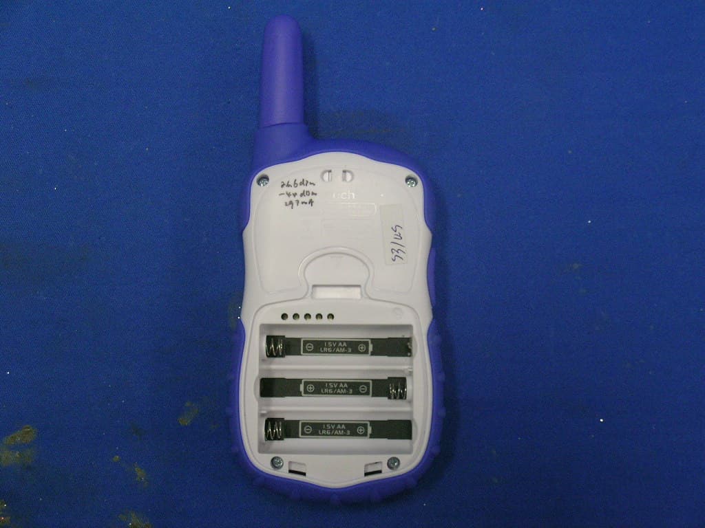
Click to zoom
Application Details
- Equipment Class
- FRF - Part 95 Family Radio Face Held Transmitter
- Date of Grant
- Jun 26, 2010
- Application Purpose
- Original Equipment
- Date of Application
- Jun 26, 2010
- Equipment Note
- Two Way Radio with FRS
- Frequency Range
- 462.58750000 - 467.56250000
- Company
- VTech Electronics Limited
- Country
- Hong Kong
Documents & Files
Document Text
Text extracted from the exhibit documents filed with the FCC. Open a document above to read the original.
Users Manual
© 2010 VTech Printed in China 91-002479-000 User’s Manual READ THIS MANUAL CAREFULLY BEFORE OPERATING THIS PRODUCT FOR SAFE USAGE AND COMPLIANCE WITH RF ENERGY EXPOSURE LIMITS To learn more about VTech ® toys, visit www.vtechuk.com 3 INTRODUCTION Thank you for purchasing the VTech ® Text & Chat Walkie-Talkies™! VTech ® Text & Chat Walkie-Talkies™ are a pair of two-way radios loaded with lots of cool features! Customize your personal profile by choosing a cartoon face as your avatar. The walkie-talkies come equipped with text messaging, animated picture messaging, and card messaging with more than 70 preset messages. Enjoy funny lip-sync animations while chatting. Three built-in games help build concentration, observation and eye-hand coordination skills. SAFETY INFORMATION RF EXPOSURE CONTROL GUIDELINES Your VTech ® Text & Chat Walkie-Talkies™ contain a receiver and a low power transmitter. When the Talk Button is pressed, it sends out radio frequency (RF) signals. To control your exposure and ensure compliance with the RF exposure guidelines adopted by the Federal Communications Commissions (FCC), always adhere to the following procedures: • Press the Talk Button ONLY when you are speaking. • Release the Talk Button when you are not speaking. • Transmit (talk) no more than 50% of the time. When speaking, hold the Text & Chat Walkie- Talkies™ in a vertical position with the microphone at least 2 inches (5 cm) away from your mouth. When sending messages, position the Text & Chat Walkie-Talkies™ antenna 2 inches (5 cm) from your body. WARNING: • Never use the Text & Chat Walkie-Talkies™ while driving or during any sporting activities as it may lead to accidents causing injuries. • Turn the Text & Chat Walkie-Talkies™ off in an aircraft or any facility where posted notices restrict the use of radios or cellular telephones. Hospitals or health care facilities may be using equipment that is sensitive to RF energy. • Never use the Text & Chat Walkie-Talkies™ where personal medical devices such as pacemakers or hearing aids are in use. Turn the walkie-talkies off immediately if there is any reason to suspect that interference is taking place. • Never use the Text & Chat Walkie-Talkies™ in front of a vehicle’s air- bag. If the air-bag deploys, it could propel the walkie-talkie and cause injuries. Introduction/Safety Information 4 Product Features • Never use the Text & Chat Walkie-Talkies™ or change the batteries in potentially explosive atmospheres as sparks in such areas could result in an explosion. • Never use the Text & Chat Walkie-Talkies™ in or near a mining facility which uses remotely triggered explosives or in areas labeled “Blasting Area.” Premature or accidental detonation may result. • Never attempt to modify or in any way increase the output power of the Text & Chat Walkie-Talkies™ as it may cause a violation of the technical regulations of Part 15 of FCC Rules. • Avoid exposing the Text & Chat Walkie-Talkies™ to water or extreme tempuratures. • Text & Chat Walkie-Talkies™ comply with FCC regulations for use in the United States and Canada. Use in other countries may be prohibited or restricted by local regulation. Please check with the local regulating agency before using this device outside of the United States or Canada. PRODUCT FEATURES PRoDUCT LAYoUT AND BUTToNS On/Off ButtonTalk Button Microphone Card Message ButtonWish Message Button Emotion Message ButtonGift Message Button OK ButtonHome Button Mailbox ButtonGame Button Left/Right Buttons 5 Product Features & Specifications Button nameFeature On/Off ButtonPress this button to turn the unit on or off. Left/Right Buttons Press these buttons to make selections. Press both buttons together to enter the set-up menu. OK ButtonPress this button to confirm a choice or action. Mailbox ButtonPress this button to read the messages in your mailbox. Card Message Button Press this button to enter the Card Message menu. Emotion Message Button Press this button to enter the Emotion Message menu. Gift Message Button Press this button to enter the Gift Message menu. Wish Message Button Press this button to enter the Wish Message menu. Game ButtonPress this button to go to the Games menu. Home ButtonPress this button to enter walkie-talkie mode. Talk ButtonPress and hold this button when speaking. Release the button to listen. INCLUDED IN THIS PACKAGE • Two VTech ® Text & Chat Walkie-Talkies™ • One instruction manual WARNING: All packing materials such as tape, plastic sheets, wire ties and tags are not part of this toy, and should be discarded for your child’s safety. PRODUCT SPECIFICATIONS • Up to 1 mile* range for chatting and messaging. • 4 chatting groups allow an unlimited number of members. • Ability to communicate with any FRS 2-way radio (For more details see the Communicating with other FRS 2-way Radios section below.) • Ability to send animated picture messages with special sound effects. • 4 incoming message notification tones. • Mailbox for storing up to 15 messages. 6 * Your Text & Chat Walkie-Talkies™ will achieve the maximum operating range when communicating in flat open areas with no trees or buildings to obstruct the signal. Under these ideal conditions, you may achieve range up to a one mile radius. The following conditions tend to reduce the range. • One or both walkie-talkies are being used indoors. • There are large obstructions such as buildings, trees, vehicles, hills, etc. between radios. • The batteries are running low. GETTING STARTED BATTERY INSTALLATION • Make sure the unit is turned OFF. • Locate the battery cover on the back of the unit. • Remove the battery cover and install 3 “AA” size batteries as illustrated. • Replace the battery cover. BATTERY NOTICE • The use of new alkaline batteries is recommended for maximum performance. • Non-rechargeable batteries are not to be recharged. • Rechargeable batteries are to be removed from the toy before being charged (if removable). • Rechargeable batteries are only to…
Text truncated - open the document above for the full version.
External Photos
INTERTEK TESTING SERVICES External Photos FCC ID: G2R-115300 IC : 1135D-115300 external photos - 1 of 2 INTERTEK TESTING SERVICES External Photos FCC ID: G2R-115300 IC : 1135D-115300 external photos - 2 of 2
ID Label/Location Info
80-115300 80-115306 1153 Engraving1153 Engraving 80-115303 80-115304 80-115305 80-115322 80-115323 80-115354 80-115355 MADE IN CHINA FABRIQUÉ EN CHINE 1153 FCC ID: G2R-115300 IC: 1135D-115300 MADE IN CHINA FABRIQUÉ EN CHINE 1153 12.9 27.8 18.75.4 7.57.1 4.6 3.2 12.9 27.8 18.75.4 7.57.1 4.6 3.2
Internal Photos
INTERTEK TESTING SERVICES Internal photos FCC ID: G2R-115300 IC: 1135D-115300 internal photos - 1 of 5 Internal Photo - 1 Internal Photo - 2 INTERTEK TESTING SERVICES Internal photos FCC ID: G2R-115300 IC: 1135D-115300 internal photos - 2 of 5 Internal Photo - 3 Internal Photo - 4 INTERTEK TESTING SERVICES Internal photos FCC ID: G2R-115300 IC: 1135D-115300 internal photos - 3 of 5 Internal Photo - 5 Internal Photo – 6 INTERTEK TESTING SERVICES Internal photos FCC ID: G2R-115300 IC: 1135D-115300 internal photos - 4 of 5 Internal Photo - 7 Internal Photo - 8 INTERTEK TESTING SERVICES Internal photos FCC ID: G2R-115300 IC: 1135D-115300 internal photos - 5 of 5 Internal Photo - 9 Internal Photo - 10
RF Exposure Info
INTERTEK TESTING SERVICES FCC ID: G2R-115300 RF exposure - 1 of 1 For Specific Absorption Rate (SAR) evaluation of the walkie talkie, with reference to Mobile and Portable Device RF Exposure Procedures and Equipment Authorization Policies, portable transmitter with output power less than Power Thresholds for PTT devices, and operating greater than that distance which show in the table 1 (>=1.0cm) from person’s body can be exempt from SAR test. The output power for portable transmitters is defined as emission radiated power (ERP) with 50% duty cycle. For the portable transmitter of the tested model of 1153, the measured maximum effective radiated power was 120(mW). From these data, the radiated power with 50 % duty cycle is : The radiated power = 120(mW)*50% = 60(mW) From the above calculation, output power obtained in method is less than low threshold , it is concluded that the device can be exempt from SAR test. Table 1- SAR Evaluation Power Thresholds for PTT devices, f ≤ 0.5 GHz Exposure Conditions mW Held to face >= 2.5cm 250 Body-worn >= 1.5cm 200 Body-worn >= 1.0cm 150 1. The time-averaged output power, corresponding to the required PTT duty factor, is compared with these thresholds. 2. The closest distance between the user and the device or its antenna is used to determine the power thresholds.
Test Report
INTERTEK TESTING SERVICES Occupied Bandwidth Plots FCC ID: G2R-115300 IC: 1135D-115300 bw - 1 of 1 Plot CH 2 Plot CH 4 (DATA)
Test Report
Code: FCC95a IC210a_FreqChar/Effective Date: 11 May 2010 Page 8 of 11 INTERTEK TESTING SERVICES Audio Low Pass Filter Response -70.0-60.0-50.0-40.0-30.0-20.0-10.0 0.0 10.0 1 10 100 Frequency (kHz) dB relative to 1 kHz LPF ResponseTIA/EIA-603C Audio Input Strength = 50mVrms FCC ID: G2R-115300 lpf - 1 of 1 60 log (F/3)
Test Report
Code: FCC95a IC210a_FreqChar/Effective Date: 11 May 2010 Page 4 of 11 INTERTEK TESTING SERVICES Modulation Frequency Response -30.00-25.00-20.00-15.00-10.00 -5.00 0.00 100 600 1100 1600 2100 2600 3100 3600 4100 4600 Modulation Frequency (Hz) Audio Frequency Response FCC ID: G2R-11530 0 mfr - 1 of 1
Test Report
Code: FCC95a IC210a_FreqChar/Effective Date: 11 May 2010 Page 6 of 11 INTERTEK TESTING SERVICES Modulation Limiting Characteristic 0.0000.5001.0001.5002.0002.500 47 57 67 77 87 97 107 117 127 137 Modulation Input (dBSPL) Frequency Deviation (kHz) 500Hz1000Hz2500Hz3125Hz FCC ID: G2R-115300 mlc - 1 of 1
Test Report
- The test report only allows to be revised the retention period issued date unless further standard or the requirement was noticed. - This report is for the exclusive use of Intertek's Client and is provided pursuant to the agreement between Intertek and its Client. Intertek's responsibility and liability are limited to the terms and conditions of the agreement. Intertek assumes no liability to any party, other than to the Client in accordance with the agreement, for any loss, expense or damage occasioned by the use of this report. Only the Client is authorized to permit copying or distribution of this report and then only in its entirety. Any use of the Intertek name or one of its marks for the sale or advertisement of the tested material, product or service must first be approved in writing by Intertek. The observations and test results in this report are relevant only to the sample tested. This report by itself does not imply that the material, product, or service is or has ever been under an Intertek certification program. Intertek Testing Services Hong Kong Ltd. 2/F., Garment Centre, 576 Castle Peak Road, Kowloon, Hong Kong. Tel: (852) 2173 8888 Fax: (852) 2785 5487 Website: www.hk.intertek-etlsemko.com VTech Electronics Limited Application For Certification Two Way Radio with FRS (FCC ID: G2R-115300) HK10050660-1 KS/ cl June 22, 2010 INTERTEK TESTING SERVICES Test Report Number: HK10050660-1 FCC ID: G2R-115300 Page 1 of 40 MEASUREMENT/TECHNICAL REPORT Applicant : VTech Electronics Limited Trade Name/Model No : 1153 Date : June 22, 2010 This report concerns (check one:)Original Grant X Class II Change Equipment Type: FRF – Part 95 Family Radio Face Held Transmitter Deferred grant requested per 47 CFR 0.457(d)(1)(ii)? Yes No X If yes, defer until: date Company Name agrees to notify the Commission by: date of the intended date of announcement of the product so that the grant can be issued on that date. Report prepared by: Sit Kim Wai, Ken Intertek Testing Services Hong Kong Ltd. 2/F., Garment Centre, 576 Castle Peak Road, Kowloon, Hong Kong. Phone: 852-2173-8538 Fax: 852-2741-1693 INTERTEK TESTING SERVICES Test Report Number: HK10050660-1 FCC ID: G2R-115300 Page 2 of 40 Table of Contents 1.0 General Description............................................................................................ 4 1.1 Product Description ............................................................................................ 4 1.2 Test Methodology............................................................................................... 5 1.3 Test Facility........................................................................................................ 5 2.0 System Test Configuration................................................................................. 7 2.1 Justification ........................................................................................................ 7 2.2 EUT Exercising Software.................................................................................... 8 2.3 Special Accessories ........................................................................................... 8 2.4 Measurement Uncertainty .................................................................................. 8 2.5 Equipment Modification ...................................................................................... 8 2.6 Support Equipment............................................................................................. 8 3.0 RF Power Output (Section 2.1046(a), 95.639(d))............................................ 10 4.0 Modulation Characteristics (Section 2.1047(a)(b), 95.637(a), 95.637(b))......... 14 4.1 Modulation Frequency Response.................................................................... 15 4.2 Modulation Limiting Characteristics................................................................. 17 4.3 Audio Low Pass Filter Response..................................................................... 19 5.0 Occupied Bandwidth (Section 2.1049, 95.633(c)).......................................... 22 6.0 Spurious Emission........................................................................................... 25 6.1 Power of Spurious Radiation (Section 2.1053, 95.635(b)) .............................. 26 7.0 Frequency Stability (Section 2.1055(a)(b)(d), 95.621(b), 95.627(b))................ 32 7.1 Frequency Tolerance ...................................................................................... 33 7.2 Temperature Extreme Condition ..................................................................... 35 7.3 Voltage Extreme Condition.............................................................................. 37 8.0 Digital Transmission (Section 95.193(b))....................................................... 40 INTERTEK TESTING SERVICES Test Report Number: HK10050660-1 FCC ID: G2R-115300 Page 3 of 40 EXHIBIT 1 GENERAL DESCRIPTION INTERTEK TESTING SERVICES Test Report Number: HK10050660-1 FCC ID: G2R-115300 Page 4 of 40 1.0 General Description 1.1 Product Description The Equipment Under Test (EUT) is a Two Way Radio with FRS operating between 462.5875MHz – 467.5625MHz. The EUT is powered by 4.5V (3 x “AA” size 1.5V alkaline batteries). Transmitter Portion (i) Type of Emission : FRS (Channel 1-4): 5K68F3E, FRS (Channel 1-4): 7K40F2D (ii) Frequency Range : FRS 1-3 Channels from 462.5875MHz to 462.6875MHz FRS 4 Channel 467.5625MHz (iii) Maximum Power Rating : FRS: 0.12W ERP (iv) Antenna Type : Integral, vertically polarized (v) Antenna Gain : 0dBi (vi) DC Voltage and DC Current of final RF amplifying device (refer to technical specification) : 2.5VDC and 280mA respectively. The Model: 80-115300 and 80-115350 are the same as the Model: 1153 in electrical designs, including software & firmware, PCB layout and construction design/Physical design/Enclosure. The only differences between these model are color and model number. The brie…
Text truncated - open the document above for the full version.
Test Report
INTERTEK TESTING SERVICES Spurious Emission Plots FCC ID: G2R-115300 IC: 1135D-115300 spurious - 1 of 1 Plot CH 2 Plot CH 4 (DATA)
Test Report
INTERTEK TESTING SERVICES Digital Transmission Plots FCC ID: G2R-115300 IC: 1135D-115300 spurious - 1 of 1 Plot Timing 1 Plot Timing 2
Test Setup Photos
INTERTEK TESTING SERVICES The Worst Case Configuration Photographs – Mode: Transmission FCC ID: G2R-115300 IC: 1135D-115300 config photos (radiated emission) - 1 of 1 Radiated Emission Front View Rear View
Contact Information
Applicant
Antony Wong(Senior Manager)
Technical Contact
Intertek Testing Services Hong Kong LtdKen Sit
[email protected]852-21738888
Flat D 5/F Garment Centre · Kowloon · Hong Kong
Non-Technical Contact
Intertek Testing Services Hong Kong LtdKen Sit
[email protected]852-21738888
Test Firm
Intertek Testing Services Hong Kong Ltd.Billy Chow
Technical Specifications
| # | Rule Parts | Frequency Range | Power Output | Emission | Tolerance |
|---|---|---|---|---|---|
| 2 | 95B | 462.5875 MHz - 467.5625 MHz | 120.00 mW | 7K40F2D | 1.84 ppm |
Other Applications from VTech Electronics Limited
G2R-7042
Sep 16, 2026Mini Paws
Equipment Class
DXX - Part 15 Low Power Communication Device TransmitterG2R-5967
Sep 10, 2026Secret Safe Locker
Equipment Class
DSS - Part 15 Spread Spectrum TransmitterG2R-6250
Aug 03, 2026LET S RECORD LEARNING SPEAKER
Equipment Class
DSS - Part 15 Spread Spectrum TransmitterG2R-5909
Apr 08, 2026Microphone Pro
Equipment Class
DSS - Part 15 Spread Spectrum TransmitterG2R-5944
Mar 17, 2026My Mini Locker
Equipment Class
DSS - Part 15 Spread Spectrum Transmitter