G6D337A-R01Remote Control Toy Transmitter
New Bright Industrial Co Ltd
Click to zoom
Application Details
- Equipment Class
- DXX - Part 15 Low Power Communication Device Transmitter
- Date of Grant
- Apr 01, 2001
- Application Purpose
- Original Equipment
- Date of Application
- Apr 01, 2001
- Equipment Note
- Remote Control Toy Transmitter
- Frequency Range
- 27.14500000 - 27.14500000
- Company
- New Bright Industrial Co Ltd
- Country
- Hong Kong
Documents & Files
Document Text
Text extracted from the exhibit documents filed with the FCC. Open a document above to read the original.
Users Manual
Instruction Manual for Transmitters TX-337A-R01 and TX-3377A-R01 Remark:Modifications not authorized by the manufacturer may void users authority to operate this device.
External Photos
FCC ID: G6D337A-R01 PHOTOGRAPH OF THE PRODUCT FRONT VIEW OF THE PRODUCT REAR VIEW OF THE PRODUCT
Internal Photos
FCC ID: G6D337A-R01 PHOTOGRAPH OF THE PRODUCT INNER CIRCUIT TOP VIEW INNER CIRCUIT BOTTOM VIEW
Operational Description
FCC ID: G6D337A-R01 Circuit Description The 27.145MHz crystal oscillator drives the base of Q2 the final/buffer amplifier. The modulation provided by Mic. The output of Q2 has the matching network consisting of L3 and C6 that limit the harmonic content and effect the proper coupling of the antenna to the output stage. Antenna, Ground and Power Source The antenna consists of a 29cm long matel wire. There is no external ground connection. The ground is only that of the printed circuit board. Electric current is supplied by a 3Volt (“AA” size battery x 2) primary storage cell.
Test Report
Date: 2001-02-08 TEST REPORT Page 1 of 8 No.: HM104018 Law Man KitSteven TsangPatrick Wong Testing EngineerVerify byPatrick Wong for Managing Director APPLICANT: (CODE: NEB001) NEW BRIGHT INDUSTRIAL CO., LTD. 9/F., New Bright Building, 11 Sheung Yuet Road, Kowloon Bay, Kowloon, Hong Kong. DATE OF SAMPLES RECEIVED:2001-01-23 SUBMITTED SAMPLE(S): 1 sample per model DATE OF TESTING: 2001-01-31 DESCRIPTION OF SAMPLE(S): A sample of product said to be: Product:RADIO CONTROL TOY VEHICLE TRANSMITTER Manufacturer:NEW BRIGHT INDUSTRIAL CO., LTD. Model Number:TX-337A(T)-R01-27MHz Brand Name:NEW BRIGHT Rating: 3Vd.c.(“AA” size battery × 2) Origin:CHINA INVESTIGATIONS REQUESTED: Measurement to the relevant clauses of F.C.C. Rules and Regulations Part 15 Subpart C - Intentional Radiator. RESULT/ REMARK:Please see attached sheet(s). CONCLUSION: From the measurement data obtained, the tested sample was considered to have COMPLIED with the clause 15.227 of Federal Communications Commission Rules and Regulations Part 15. TEST EQUIPMENT AUDIT: Please see Appendix A Date: 2001-02-08 TEST REPORT Page 2 of 8 No.: HM104018 T E S T S U M M A R Y *** INTENTIONAL RADIATOR *** (1) Measurement of Emission of RF energy on the carrier frequency..........Satisfactory (2) Measurement of the out-of band emissions including harmonics...........Satisfactory (3) Measurement of Emission Within Band Edges.......................................Satisfactory (4) Measurement of Line-Conducted Voltage onto AC Power Line............Not applicable T E S T D A T A Please refer to the attached result sheets. Date: 2001-02-08 TEST REPORT Page 3 of 8 No.: HM104018 *** INTENTIONAL RADIATOR *** (1) Measurement of Radiated Interference TEST REFERENCE:FCC Rules Part 15 Subpart Section 15.227(26.96-27.28MHz) TEST CONDITION:Normal TEST DATE:2001-01-31 Emission of RF energy on the carrier frequency -- 27.145 MHz (PEAK VALUE) ================================================================== EmissionMeterPolarizationAntennaField Strength FCC Limit FrequencyReadingFactor(at 3m) MHzdB( μV)H-VdBdB(μV/m)μV/mμV/m 27.146.3V+18.564.81737.8100000.0 ================================================================== Emission of RF energy on the carrier frequency -- 27.145 MHz (AVERAGE VALUE) ================================================================== EmissionMeterPolarizationAntennaField Strength FCC Limit FrequencyReadingFactor(at 3m) MHzdB( μV)H-VdBdB(μV/m)μV/mμV/m 27.142.9V+18.561.41174.910000.0 ================================================================== ... to be continued Date: 2001-02-08 TEST REPORT Page 4 of 8 No.: HM104018 *** INTENTIONAL RADIATOR *** (1) Measurement of Radiated Interference . . Continued .. TEST REFERENCE:FCC Rules Part 15 Subpart Section 15.227(26.96-27.28MHz) TEST CONDITION:Normal TEST DATE:2001-01-31 The out-of-band emissions, including harmonics (25-1000 MHz) (CISPR VALUE) ================================================================== EmissionMeterPolarizationAntennaField Strength FCC Limit FrequencyReadingFactor(at 3m) MHzdB( μV)H-VdBdB(μV/m)μV/mμV/m ###54.311.5+12.924.416.6100.0 81.4<1.0+8.9<9.9<3.1100.0 108.6<1.0+12.2<13.2<4.6150.0 135.7<1.0+10.8<11.8<3.9150.0 162.9<1.0+9.5<10.5<3.3150.0 190.0<1.0+11.1<12.1<4.0150.0 217.2<1.0+12.2<13.2<4.6200.0 244.3<1.0+13.5<14.5<5.3200.0 271.5<1.0+16.0<17.0<7.1200.0 298.6<1.0+16.5<17.5<7.5200.0 325.7<1.0+16.6<17.6<7.6200.0 352.9<1.0+16.7<17.7<7.7200.0 380.0<1.0+17.4<18.4<8.3200.0 407.2<1.0+18.2<19.2<9.1200.0 434.3<1.0+19.5<20.5<10.6200.0 461.5<1.0+20.1<21.1<11.4200.0 488.6<1.0+20.3<21.3<11.6200.0 515.8<1.0+20.9<21.9<12.4200.0 542.9<1.0+22.1<23.1<14.3200.0 570.0<1.0+22.8<23.8<15.5200.0 597.2<1.0+23.3<24.3<16.4200.0 624.3<1.0+23.4<24.4<16.6200.0 ... to be continued Date: 2001-02-08 TEST REPORT Page 5 of 8 No.: HM104018 *** INTENTIONAL RADIATOR *** (1) Measurement of Radiated Interference . . Continued .. TEST REFERENCE:FCC Rules Part 15 Subpart Section 15.227(26.96-27.28MHz) TEST CONDITION:Normal TEST DATE:2001-01-31 The out-of-band emissions, including harmonics (25-1000 MHz) (CISPR VALUE) ================================================================== EmissionMeterPolarizationAntennaField Strength FCC Limit FrequencyReadingFactor(at 3m) MHzdB(μV)H-VdBdB(μV/m)μV/mμV/m ###651.5<1.0+23.6<24.6<17.0200.0 678.6<1.0+24.9<25.9<19.7200.0 705.8<1.0+25.1<26.1<20.2200.0 732.9<1.0+25.4<26.4<20.9200.0 760.1<1.0+26.4<27.4<23.4200.0 787.2<1.0+26.8<27.8<24.5200.0 814.4<1.0+26.7<27.7<24.3200.0 841.5<1.0+26.1<27.1<22.6200.0 868.6<1.0+26.8<27.8<24.5200.0 895.8<1.0+27.1<28.1<25.4200.0 922.9<1.0+27.5<28.5<26.6200.0 950.1<1.0+28.1<29.1<28.5200.0 977.2<1.0+28.2<29.2<28.8500.0 ================================================================== ====================SUMMARY=================== All data is within limits ============================================= Broad-band Antennas were used both polarizations of emissions were measured. polarizations at highest reading indicated as: H -- HorizontalV -- Vertical ============================================= Date: 2001-02-08 TEST REPORT Page 6 of 8 No.: HM104018 *** INTENTIONAL RADIATOR *** (2) Measurement of Emissions Within Band Edges. TEST REFERENCE: FCC Rules Part 15 section 15.227(26.96-27.28MHz) TEST CONDITION: Normal TEST DATE : 2001-01-31 RESULTS AND NOTES L: FCC Lower Band Edge ..........................................................................-> 26.960MHz H: FCC Higher Band Edge .........................................................................-> 27.280MHz C: Unmodulated carrier at frequency .........................................................-> 27.145MHz D: No. of dB from unmodulated carrier .....................................................-> 46.10dB SPECTRUM ANALYZER SETTINGS Resolution bandwidth: 12.8KHz Frequency span: 10.0KHz/div No. of dB/div: 10.0dB/div FCC Limit Minimum No. of dB from unmodulated carrier required : 26.0dB ================SUMMARY================ All data is within limits ===============…
Text truncated - open the document above for the full version.
Test Report
Chris Harvey From:Alice Wong [[email protected]] Sent:Friday, March 02, 2001 7:41 AM To:Chris Harvey Cc:[email protected]; Grace * Chiu; EED - Choy, Kitty Subject:Re: Test Report Dear Chris, Thank you for your e-mail, 1) We have measurement procedure used in these application. (NASI C63.4:1992). 2) In our measurement process, we have performed measurements in 3 orthogonal axes, by moving the sample in corresponding directions. Besides the measurement were performed on both horizontal and vertical polarities of the antenna from 1m and 4m the turn table was rotated from 0 to 360. The worse case was recorded during the above process. Please see attached file "Method" for test method. I have hoilday on 03 March 2001 to 07 March 2001, If have any question. Please contact Ms Kitty Choy ([email protected]) Thanks, have nice hoilday. Best Regards Alice ----- Original Message ----- From: "Chris Harvey" <[email protected]> To: "'Alice Wong'" <[email protected]>; "Chris Harvey" <[email protected]> Cc: "EED - Choy, Kitty" <[email protected]>; "Marianne Bosley" <[email protected]>; "Greg Czumak" <[email protected]> Sent: Wednesday, February 28, 2001 10:16 AM Subject: RE: Test Report > Alice, I have reviewed the 2 test reports for the below referenced FCC ID > application and have the following items that need completion or correction > (or please direct me as to where I can find them in the documentation > provided). > > 1. Please indicate the measurement standard used. Just stating that it was > tested in accordance with 15.235 or 15.227 is not sufficient. Please see > FCC 15.31 for guidance. the measurement standard must be something that is > recognized by the FCC, such as ANSI C 63.4:1992. > > 2. There is no indication that the device has been tested in 3 orthogonal > axis (X, Y and Z axis). Please re-measure or indicate that this has been > performed. > > 3. The test of the report indicates that both Horizontal and Vertical data > have been taken, however the data tables do not indicate the polarity of the > antenna during measurements. Please correct this oversight. > > also please note that in the Label Photographs,, there is a note that the > FCC ID or FCC DoC label is placed here. Please note that the FCC DoC > labeling does not apply to these types of devices. Please correct this for > future applications (not necessary to correct these 2 applications. > > Best regards, > > Chris Harvey > > Chris Harvey > EMC Lab Director > MET Laboratories, Inc. > 1-800-638-6057 > [email protected] > www.metlabs.com > > > > -----Original Message----- > > From: Alice Wong [SMTP:[email protected]] > > Sent: Monday, February 26, 2001 7:53 PM > > To: [email protected] > > Cc: EED - Choy, Kitty; [email protected] > > Subject: Test Report > > > > Dear Chris, > > > > Thank you for your e-mail, > > Please see attached file for G6D3377A-R01(66.5KB) and G6D337A-R01(69.7KB) > > test report. > > If have any question, please let me know. > > Thanks. > > > > Best Regards > > Alice > > << File: report.pdf >> << File: report.pdf >> Method.pdf
Test Report
THE HONG KONG STANDARDS AND TESTING CENTRE LIMITED Test Procedure for Radiated Emission Measurement on the OATS between 30MHz and 1GHz for Digital and Computing Devices Doc. No.:EMC/EMI/004/A Issue:1 Revision:C Date:2000-11-19 Standard: FCC Part 15:2000Page:1 of 10 g:\emc\procedur\emi004a.doc REVISION STATUS Page(s)Rev.Revision OutlineApproved ByDate ALLANew Document 2,3BTextual changes ALLCAdd extra procedure for high background noise case and include reference radiator Authorized By: _________________ Date: _________________ CONTROL STAMP NOTE: The stamp is in RED for a CONTROLLED copy. Please refer to controlled copy ONLY. THE HONG KONG STANDARDS AND TESTING CENTRE LIMITED Test Procedure for Radiated Emission Measurement on the OATS between 30MHz and 1GHz for Digital and Computing Devices Doc. No.:EMC/EMI/004/A Issue:1 Revision:C Date:2000-11-19 Standard: FCC Part 15:2000Page:2 of 10 g:\emc\procedur\emi004a.doc 1. OBJECTIVE The objective of this test is to measure radiated E-field emissions in the frequency range 30MHz to 1GHz. The main procedure is outlined in ANSI C63.4, which details the procedure for measuring RF emissions from computing devices. ANSI C63.4 must be used in conjunction with this procedure. This procedure is aimed at digital and computing devices. Other procedures are available for measurement of radiated emissions from intentional radiators and broadcast receivers. 2. REFERENCES 2.1 FCC Part 15Code of Federal Regulations, title 47, part 15:2000 2.2 ANSI C63.4:2000Methods of measurement of radio-noise emissions from low voltage electrical and electronic equipment in the range 9kHz to 40GHz. 2.3 CISPR 16-1:1993Radio disturbance and immunity measurement apparatus 2.4 EMC/UNC/001Uncertainty budgets for EMC department 2.5 EMC/MNT/001EMC department equipment maintenance and operation check procedures 3. DEFINITIONS B/WBandwidth EMCElectro-Magnetic Compatibility EUTEquipment Under Test IFIntermediate Frequency OATSOpen Area Test Site rfRadio-Frequency 4. APPARATUS ItemEquip. No.Description 1EM007Spectrum Analyser 2EM008Spectrum Analyser 3EM009Quasi-Peak Adapter 4EM010Pre-selector 5EM011Attenuator / Driver 6EM012Pre-Amplifier 7EM017Antenna 8EM006Spectrum Analyser 9EM034Pre-Amplifier 10EM004Receiver 11EM016Antenna 12EM125Reference Radiator 13EM0823m Semi-Anechoic Chamber 14EM083Open Area Test Site THE HONG KONG STANDARDS AND TESTING CENTRE LIMITED Test Procedure for Radiated Emission Measurement on the OATS between 30MHz and 1GHz for Digital and Computing Devices Doc. No.:EMC/EMI/004/A Issue:1 Revision:C Date:2000-11-19 Standard: FCC Part 15:2000Page:3 of 10 g:\emc\procedur\emi004a.doc 5. APPARATUS CONFIGURATION 5.1 Pre-Scan The pre-scan test equipment should be connected up as follows:- EUT or Ref. Rad EM016 Bi-log Antenna EM034 Pre-Amplifier EM006 Spectrum Analyser EM004 Receiver CHAMBER EM082 CONTROL ROOM PLAN VIEW OF EMC CHAMBER & CONTROL ROOM THE HONG KONG STANDARDS AND TESTING CENTRE LIMITED Test Procedure for Radiated Emission Measurement on the OATS between 30MHz and 1GHz for Digital and Computing Devices Doc. No.:EMC/EMI/004/A Issue:1 Revision:C Date:2000-11-19 Standard: FCC Part 15:2000Page:4 of 10 g:\emc\procedur\emi004a.doc 5.2 Final (OATS) Measurement The test equipment should be connected up as follows:- EUT or Ref. Rad EM017 EM007 EM008 EM009 EM010 EM011 EM012 Spectrum Analyser System OATS EM083 CONTROL ROOM PLAN VIEW OF STC OATS & CONTROL ROOM Please refer to section 5.3 for cabling details of the spectrum analyser system. THE HONG KONG STANDARDS AND TESTING CENTRE LIMITED Test Procedure for Radiated Emission Measurement on the OATS between 30MHz and 1GHz for Digital and Computing Devices Doc. No.:EMC/EMI/004/A Issue:1 Revision:C Date:2000-11-19 Standard: FCC Part 15:2000Page:5 of 10 g:\emc\procedur\emi004a.doc 5.3 Final (OATS) Measurement - Spectrum Analyser System Cabling The rear of the spectrum analyser should be cabled up as follows:- J8 EM010 Pre-selector EM007 Spectrum analyser EM008 Spectrum analyser display Recorder O/P sweep I/PO/PI/PO/P O/P I/P O/P I/P VideoI/F Spectrum Analyser System Cabling Rear view, pre-amplifier(EM012) & attenuator driver (EM011) not shown for clarity GP-IB GP-IB GP-IB GP I B Private bus to spectrum analyser To computer EM009 Quasi-peak adapter THE HONG KONG STANDARDS AND TESTING CENTRE LIMITED Test Procedure for Radiated Emission Measurement on the OATS between 30MHz and 1GHz for Digital and Computing Devices Doc. No.:EMC/EMI/004/A Issue:1 Revision:C Date:2000-11-19 Standard: FCC Part 15:2000Page:6 of 10 g:\emc\procedur\emi004a.doc 6. SPECIAL PRECAUTIONS Ensure:- 1.All test instruments are within calibration. 2.That the EUT falls within the scope of the standard being applied. 3.Investigate all operating modes of the EUTand rotated about all 3 axis to obtain worse results. 4.Select the correct test limit for the EUT (either Class A or B, see FCC part 15.109 & 15.209 for details). 5.Confirm that the correct settings have been entered on the antenna mast controller and the turntable controller. i.e. the correct height/angle and limits. This should be done at the start of each days testing. 6.Ensure that the height of the antenna is updated everytime the polarity is changed. 7.If the EUT emission is covered by background noise and the level is within 6dB of the limit line (or above), then the following may be used to overcome the problem. a.Reduce the resolution bandwidth (for narrowband signal only) and attempt to resolve the background and EUT emission. For narrowband signals, the peak value will be similar to the quasi-peak. b.If the procedure in a. above is not successful, then try and locate and measure (on the OATS) an EUT emission close to the one being masked by background noise. Measure this and the masked EUT emission in the chamber. Calculate the difference between the OATS and chamber measurement for the adjacent emission. Then, for the masked emission, apply the calculated difference. Only apply this if the differ…
Text truncated - open the document above for the full version.
Test Report
Marianne Bosley From:Chris Harvey Sent:Tuesday, February 27, 2001 9:16 PM To:'Alice Wong'; Chr is Harvey Cc:EED - Choy, Kitty; Marianne Bosley; Greg Czumak Subject:RE: Test Report Alice, I have reviewed the 2 test reports for the below referenced FCC ID application and have the following items that need completion or correction (or please direct me as to where I can find them in the documentation provided). 1. Please indicate the measurement standard used. Just stating that it was tested in accordance with 15.235 or 15.227 is not sufficient. Please see FCC 15.31 for guidance. the measurement standard must be something that is recognized by the FCC, such as ANSI C 63.4:1992. 2. There is no indication that the device has been tested in 3 orthogonal axis (X, Y and Z axis). Please re-measure or indicate that this has been performed. 3. The test of the report indicates that both Horizontal and Vertical data have been taken, however the data tables do not indicate the polarity of the antenna during measurements. Please correct this oversight. also please note that in the Label Photographs,, there is a note that the FCC ID or FCC DoC label is placed here. Please note that the FCC DoC labeling does not apply to these types of devices. Please correct this for future applications (not necessary to correct these 2 applications. Best regards, Chris Harvey Chris Harvey EMC Lab Director MET Laboratories, Inc. 1-800-638-6057 [email protected] www.metlabs.com -----Origina l Message----- From:Alice Wong [SMTP:[email protected]] Sent:Monday, February 26, 2001 7:53 PM To:[email protected] Cc:EED - Choy, Kitty; [email protected] Subject:Test Report Dear Chris, Thank you for your e-mail, Please see attached file for G6D3377A-R01(66.5KB) and G6D337A- R01(69.7KB) test report. If have any question, please let me know. Thanks. Best Regards Alice << File: report.pdf >> << File: report.pdf >>
Test Setup Photos
FCC ID: G6D337A-R01 TEST SET UP PHOTOGRAPH OF THE PRODUCT
Contact Information
Applicant
Eric Kwok(Quality Manager)
Test Firm
Hong Kong Standards & Testing Cen.Wilson Wong
Technical Specifications
| # | Rule Parts | Frequency Range | Power Output |
|---|---|---|---|
| 1 | 15C | 27.145 MHz - 27.145 MHz | - |
Other Applications from New Bright Industrial Co Ltd
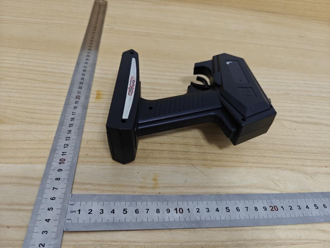
G6D8720H
Apr 09, 2024TOY Transmitter
Equipment Class
DXX - Part 15 Low Power Communication Device Transmitter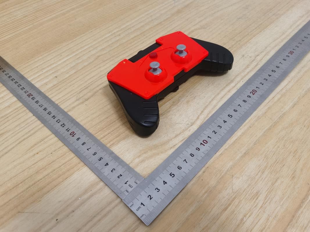
G6D3720HH2
Jan 10, 2024TOY Transmitter
Equipment Class
DXX - Part 15 Low Power Communication Device Transmitter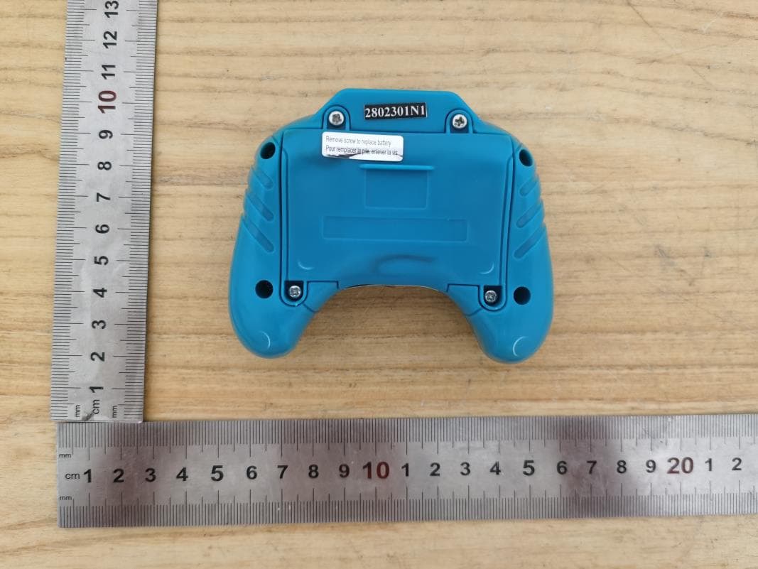
G6D43HW2
Nov 13, 2023TOY Transmitter
Equipment Class
DXX - Part 15 Low Power Communication Device Transmitter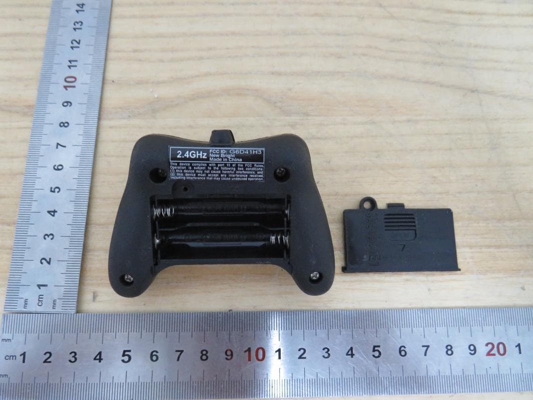
G6D41H3
Jul 09, 2023TOY Transmitter
Equipment Class
DXX - Part 15 Low Power Communication Device Transmitter
G6D31HA1
Apr 10, 2023TOY Transmitter
Equipment Class
DXX - Part 15 Low Power Communication Device Transmitter