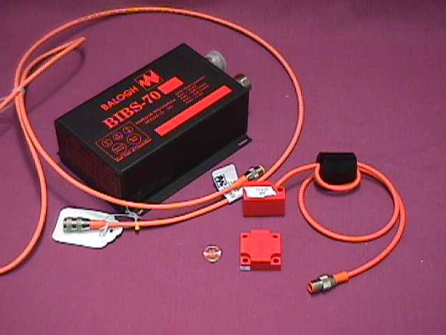
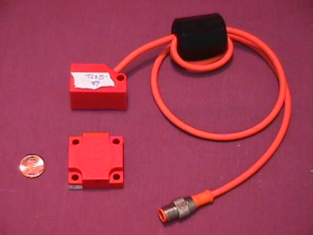
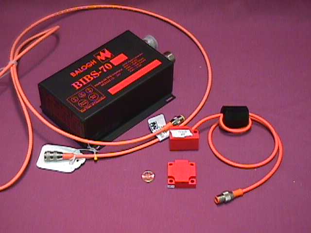
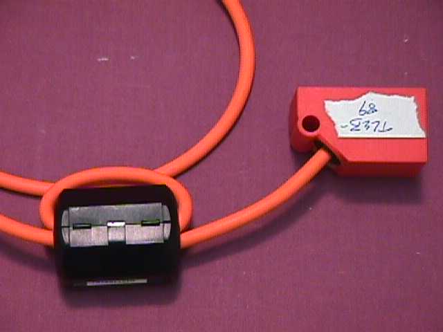
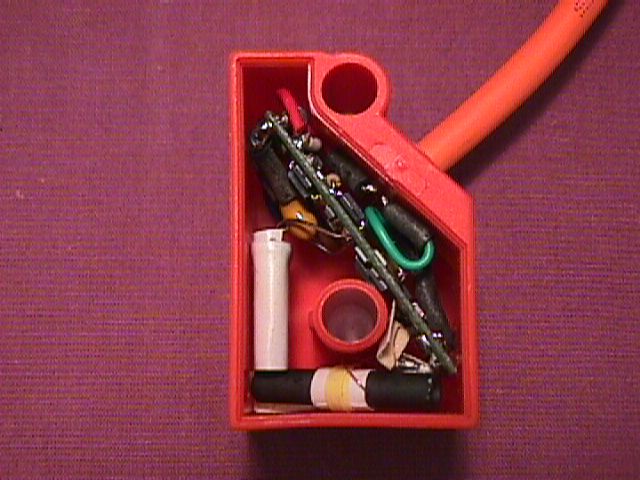
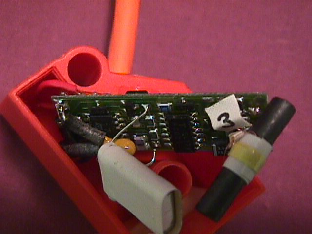
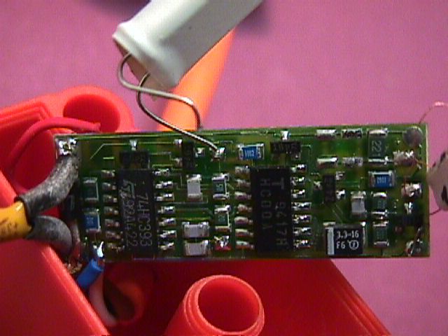
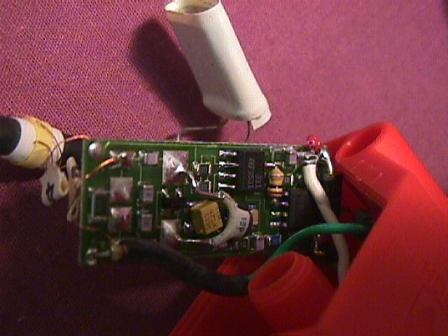
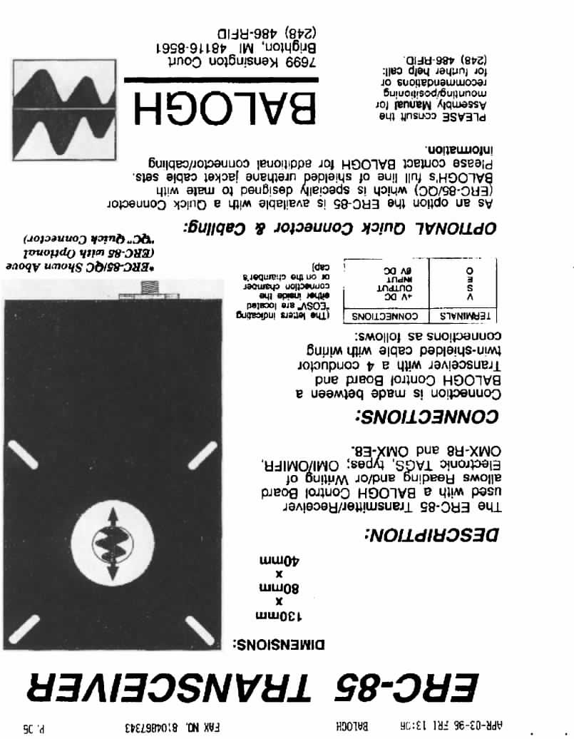
G8630TLEB89A1RF identification tag tranceiver used in product m
Balogh T A G Inc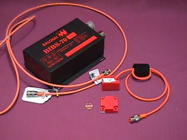
Click to zoom
Application Details
- Equipment Class
- DXT - Part 15 Low Power Transceiver, Rx Verified
- Date of Grant
- Nov 24, 1998
- Application Purpose
- Original Equipment
- Date of Application
- Sep 30, 1998
- Equipment Note
- RF identification tag tranceiver used in product m
- Frequency Range
- 1.50000000 - 1.50000000
- Company
- Balogh T A G Inc
- Country
- United States
Documents & Files
Document Text
Text extracted from the exhibit documents filed with the FCC. Open a document above to read the original.
Cover Letter(s)
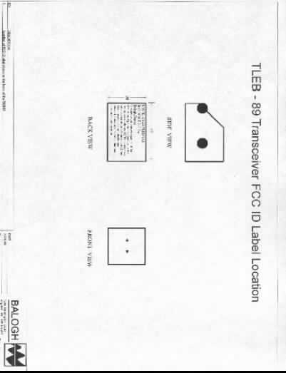
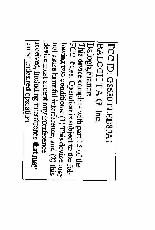
Joseph Tomashik 7699 Kensington Court Brighton, MI 48116-8561 15 July 98 reference: EMI 1074 and EMI 1084 Dear Mr. Tomashik, I am in the process of finalizing Balogh’s FCC Applications for Certification of the ERC-85 and the TLEB-89 and require your assistance in obtaining the below listed support documents. Thank you for your attention to this request. Please call me (extension 389) with any questions. ERC-85 1) FCC ID Label Final artwork or sample label (ensure CANADIAN requirement met if using one label for FCC & Canadian) 2) FCC ID Label PLACEMENT final artwork 3) Check for the US sum of $1025.00 made payable to the “FCC” you may put the FCC ID# as a reference line if desired.(one check PER application is required!) 4) Canadian Contact Person and Maintenance Facility Address TLEB-89 1) FCC ID Label Final artwork or sample label (ensure CANADIAN requirement met if using one label for FCC & Canadian) 2) FCC ID Label PLACEMENT final artwork 3)Technical Specification Data sheet for the EUT 4) Users Manual (or excerpt) showing emission type/mod, technical data, and information to the user about FCC rules 5) Check for the US sum of $1025.00 made payable to the “FCC” you may put the FCC ID# as a reference line if desired. (one check PER application is required!) 6) Canadian Contact Person and Maintenance Facility Address Sincerely, Terri Wolf Technical Manager EMC Laboratory [email protected]
Operational Description
23 Nov 1998 To: Rich Fabina ([email protected]) From: Chris Harvey ([email protected]) Re:FCC ID: G8630ERC85 (correspondence ID: 4790) Q. Provide results for AC line conducted Measurements as per 15.207(a). A. Please refer to the technical descriptions provided for the EUT. The EUT derives power from a DC powered controller, and thus the EUT and its controller do not connect to the AC mains. Therefore, conducted emissions, as per FCC Rule 15.207(a), are not applicable. Please see the Users manual and the test report for indications of how this EUT receives its power. The EUT is powered from a DC powered controller. There is no direct or indirect connection to AC power. Q. Fee issues, We have submitted a new single check in the amount of $1075 to Mellon Bank for processing. Please look out for this payment processing to happen any day now. I realize asking a banker to add 2 numbers is a little out of the question. I actually added the numbers for them, but.... Maybe I should scrutinize my bank statements a little more from now on.
Test Report
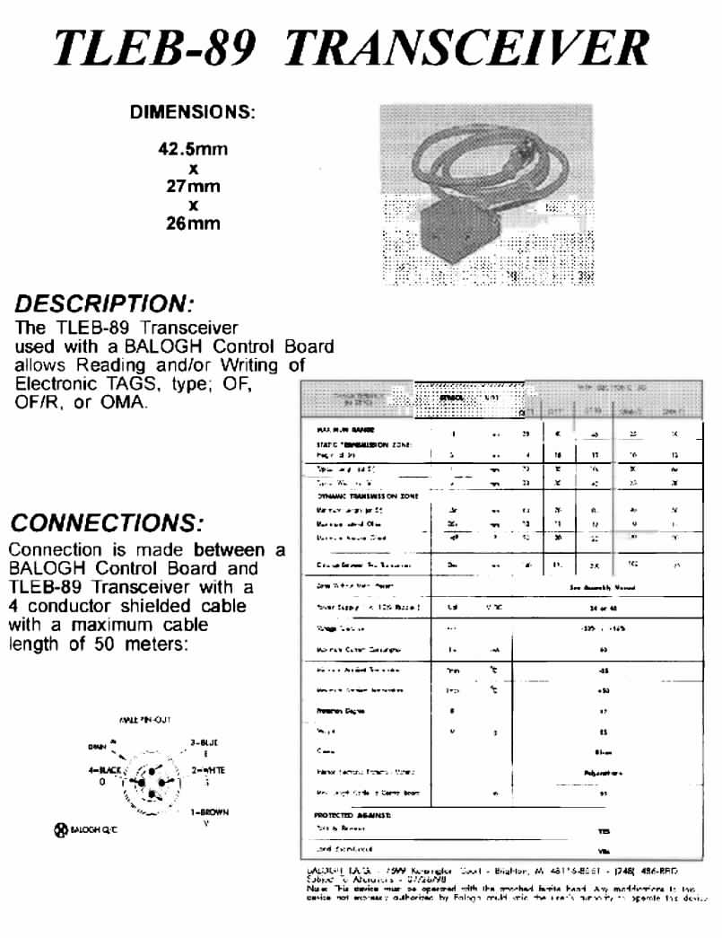
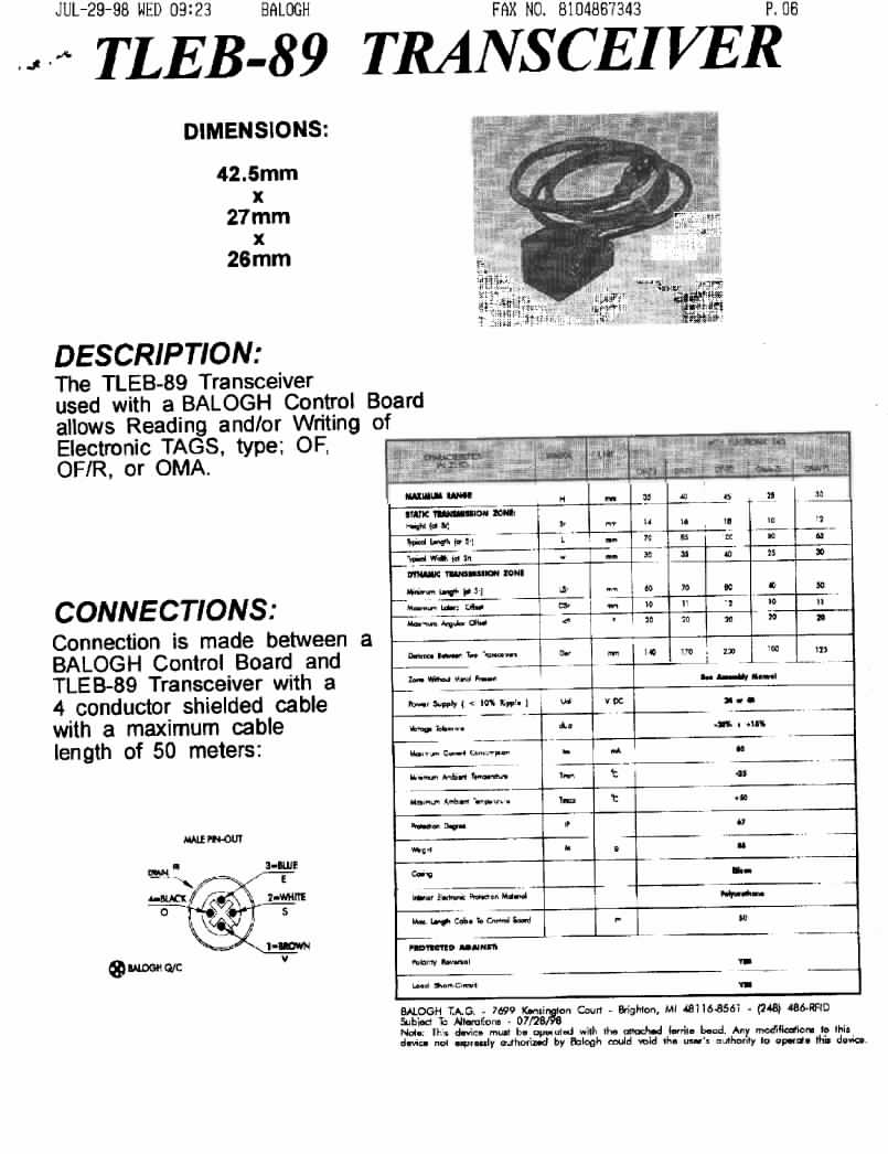
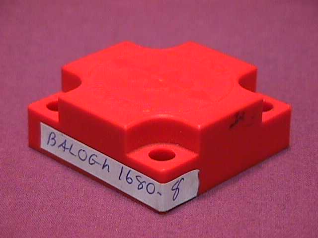
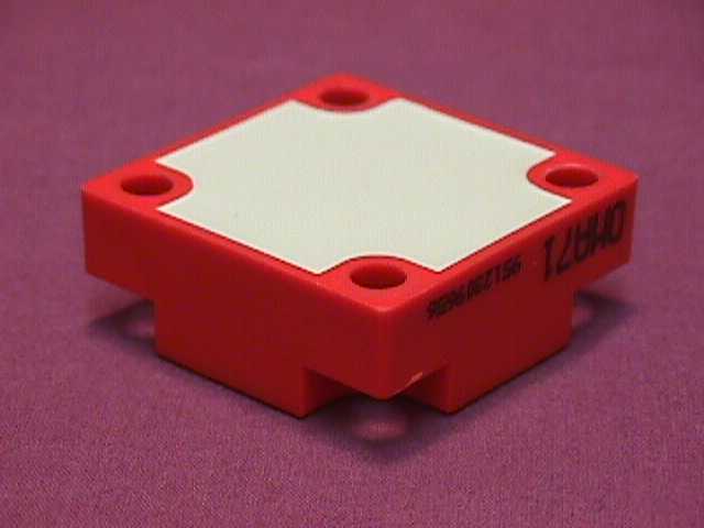
FCC ID: G8630TLEB89A1 September 25, 1998 Federal Communications Commission Authorization and Evaluation Division 7435 Oakland Mills Road Columbia, MD 21046 Attention:Applications Examiner Applicant:Balogh 7699 Kensington Court Brighton, MI 48116-8561 Equipment:TLEB-89 PUR Transceiver FCC ID: G863TLEB89 Specification: 47 CFR 15c CERTIFICATION Dear Examiner: The following application for Grant of Equipment Authorization is presented on behalf of Balogh for the Certification of their TLEB-89 PUR Transceiver. Enclosed, please find a complete data and documentation package demonstrating that this device complies with the technical requirements of 47 CFR, Part 15c, for a Transceiver. If you have any questions, please contact the undersigned, who is authorized to act as Agent. Sincerely, Chris Harvey Director, EMC Laboratory FCC ID: G8630TLEB89A1 MET Laboratories, Inc. Safety Certification - EMI - Telecom Environmental Simulation 914 WEST PATAPSCO AVENUE • BALTIMORE, MARYLAND 21230-3432 • PHONE (410) 354-3300 • FAX (410) 354-3313 ENGINEERING TEST REPORT in support of the CERTIFICATION Application for Grant of Equipment Authorization EQUIPMENT:TLEB-89 PUR Transceiver FCC ID::G8630TLEB89A1 Specification:47 CFR 15c On Behalf of the Applicant:Balogh 7699 Kensington Court Brighton, MI 48116-8561 Manufacturer:Balogh 7699 Kensington Court Brighton, MI 48116-8561 Manufacturer’s Mr. Joseph G. Tomashik Representative Test Date(s):June 18 - 19, 1998 ENGINEERING STATEMENT I ATTEST: the measurements shown in this report were made in accordance with the procedures indicated, and that the emissions from this equipment were found to be within the limits applicable. I assume full responsibility for the accuracy and completeness of these measurements. On the basis of the measurements made, the equipment tested is capable of operation in accordance with the requirements of Part 15c of the FCC Rules under normal use and maintenance. _____________________________ Kenneth Bass EMI Engineer, MET Laboratories _______________________ Chris Harvey Director, EMC Laboratory FCC ID: G8630TLEB89A1 EMI1074A- 3 -SEPT 22,1998 1.0INTRODUCTION The following data is presented on behalf of the Applicant, Balogh, as verification of the compliance of the TLEB-89 PUR Transceiver, to the requirements of 47CFR15c. 2.0TEST SITE All testing was conducted at MET Laboratories, Inc., 914 West Patapsco Avenue, Baltimore, Maryland 21230-3493. Radiated emissions measurements were performed on a three-meter open area test site (OATS). A complete site description is on file with the FCC Laboratory Division as 31040/SIT/MET. 3.0TEST EQUIPMENT USED ManufacturerEquipment Calibration DueCal. Interval Hewlett Packard8591E Spectrum Analyzer 1/29/99annual EMCOBiconical Antenna 3104 2/9/99annual EMCOEMCO Log Periodic Antenna 3/20/99annual EMCOActive Rod12/16/98annual Hewlett Packard8594EM Analyzer11/19/98annual SolarLISN6/30/99annual 4.0EQUIPMENT UNDER TEST CONFIGURATION The TLEB-89 PUR Transceiver is a low power transceiver operating at 1.5MHz and intended for use in industrial environments. Balogh Transceivers are modular components compatible with various tags. The transceiver provides energy for data transmission and reception between the Tag and Transceiver. An electromagnetic field generated by the transceiver determines the dimensions of the transmission zone. As a tag enters the transmission zone, data transfer takes place without contact through an inductive field established by the transceiver. This transmission is independent of the direction and speed of the tag. The read/write tags are remotely read or written to when the tag is in the transmission zone. Read/write tags are available with 64 byte, 2 Kbyte, or 8 Kbyte memory capacities. the front panel LED’s were visual monitored to determine the presents or absence of a tag, or a T/R fault if the T/R is not operational. 5.0TEST TYPE(S) 5.1Radiated Emissions: 47CFR15.209 FCC ID: G8630TLEB89A1 EMI1074A- 4 -SEPT 22,1998 6.0TEST RESULTS 6.1TEST TYPE: Radiated Emissions (Transmitter Portion of Transceiver) 6.1.1 TECHNICAL SPECIFICATION:47CFR15.209. Field strength of transmit @1.5MHz and measurements above10th harmonic. 6.1.2 TEST DATE(S):18 Jun 1998 6.1.3 MEASUREMENT PROCEDURES: As required by §15.209, field strength of spurious radiation measurements were made in accordance with the general procedures of ANSI C63.4-1992 "Methods of Measurement of Radio- Noise Emissions from Low-Voltage Electrical and Electronic Equipment in the Range of 9kHz to 40 GHz". Preliminary radiated emission measurements were performed inside a shielded chamber with all digital signal generators on and terminated. The frequency list from the preliminary measurements was used as a guide for making final measurements on an 3 meter open area test site. The unit was scanned over the frequency range of 1.5MHz to 15 MHZ. Calculations of fundamental and spurious limits obtained by: per 47CFR15.209 measured: (note: below 30MHz a calibrated loop may be used) Fc (tx) @ 1.500 MHZ = 46.11 dBuV w/ active rod 9.16 dB Antenna correction factor 55.27 dBuV/m @ 3m a) from table in 15.209 limit: Limit @ 1.5MHz = 24000/F(kHz) uV @ 30 m, therefore: 24000/1500= 16 uV/m @ 30m = 24.1 dBuV/m @30m per 15.31 @ <30MHz, use 40 dB/dec, therefore: 24.1 dBuV/m @ 30m 40 dB 64.1 dBuV/m @ 3m b) also from table in 15.209(c) for spurious emission limits: Limit @ 3.0 MHz & 7.50 MHz < level of the fundamental, therefore limit < 64.1 dBuV/m @3m FCC ID: G8630TLEB89A1 EMI1074A- 5 -SEPT 22,1998 Freq. MHz azimpolht (m) Ampl (dBuV) ACF (dB/m) cbl loss (dB) Corr. Ampl (dBuV/m) Limit (dBuV/m) 1.5000H1.046.119.160.555.2764.1 3.000H1.028.558.980.547.40< 64.1 7.500H1.024.369.490.534.35< 64.1 66.00270H1.021.89.70.9532.4539.0 66.00270V1.523.39.00.9533.2539.0 78.30135H2.028.806.40.9536.1539.0 78.30180V1.028.256.90.9536.1039.0 85.7090H1.528.106.70.9535.7543.5 85.70180V1.527.408.90.9537.2543.5 203.97*270H2.022.7017.51.641.8043.5 203.97180V1.020.0017.91.639.5043.5 206.98*270…
Text truncated - open the document above for the full version.
Contact Information
Applicant
Michael Karrick(Vice President)
248-486-7343Fax: 248-486-0404
Technical Contact
MET Laboratories, Inc.Chris Harvey
[email protected]410 354 3300
914 West Patapsco Ave. · Baltimore, Maryland · United States
Non-Technical Contact
MET Laboratories, Inc.Terri M Wolf
[email protected]410 354 3300
Test Firm
MET Laboratories, Inc.John Mason
Technical Specifications
| # | Rule Parts | Frequency Range | Power Output |
|---|---|---|---|
| 1 | 15C | 1.5 MHz - 1.5 MHz | - |
Other Applications from Balogh T A G Inc
G8630ERC85
Dec 13, 1998RF ID Tag Transmitter
Equipment Class
DXX - Part 15 Low Power Communication Device TransmitterG863OPO85
May 15, 1988DCD - Part 15 Low Power Transmitter Below 1705 kHz
Equipment Class
DCD - Part 15 Low Power Transmitter Below 1705 kHz