GAO-BLEYDMobile Phone
Collage Investments LLC.
Click to zoom
Application Details
- Equipment Class
- PCE - PCS Licensed Transmitter held to ear
- Date of Grant
- Aug 05, 2014
- Application Purpose
- Original Equipment
- Date of Application
- Aug 05, 2014
- Equipment Note
- Mobile Phone
- Frequency Range
- 1852.40000000 - 1907.60000000
- Company
- Collage Investments LLC.
- Country
- United States
Documents & Files
Document Text
Text extracted from the exhibit documents filed with the FCC. Open a document above to read the original.
Users Manual
1 USER MANUAL MODEL: Q‐45BLEYD 2 CONTENTS SAFETY ................................................................ 4 1 GETTING STARTED ............................................ 5 1.1 GETTING TO KNOW YOUR TOUCH PHONE ........ 5 1.2 INSTALLING THE SIM CARD, BATTERY, AND STORAGE CARD .................................................... 5 1.3 CHARGING THE BAT T E RY ............................... 7 1.4 STAT U S ICONS ................................................ 7 2 USING PHONE FEATURES .................................. 9 2.1 TURNING THE PHONE FUNCTION ON AND OFF . 9 2.2 MAKING A CALL ............................................. 9 2.3 ANSWERING AND ENDING A CALL ................ 10 2.4 IN-CALL OPTIONS ......................................... 10 2.5 USING CALL HISTORY ................................... 10 2.6 CALL SETTINGS ............................................ 10 3 SETTING ON YOUR DEVICE .............................. 11 4 ACTIVESYNC ................................................... 14 5 CONTACTS ...................................................... 15 3 6 EXCHANGING MESSAGES ................................ 16 7 INTERNET ....................................................... 18 7.1 WAY S O F CONNECTING TO THE INTERNET .... 18 7.2 BROWSER ..................................................... 19 8 EXPERIENCING MULTIMEDIA........................... 20 8.1 CAMERA & PICTURE .................................... 20 8.2 MUSIC .......................................................... 21 8.3 FM RADIO ................................................... 21 8.4 VOICE SEARCH ............................................. 22 8.5 SOUND RECORD ............................................ 22 9 OTHER APPLICATIONS ..................................... 22 9.1 CALENDAR ................................................... 22 9.2 ALARM CLOCK ............................................. 22 9.3 CALCULATOR ............................................... 24 9.4 WA R N I N G S TAT E M E N T ................................... 24 4 Safety Never attempt to disassemble your phone. You alone are responsible for how you use your phone and any consequences of its use. As a general rule, always switch off your phone wherever the use of a phone is prohibited. Use of your phone is subject to safety measures designed to protect users and their environment. Do not use your phone in damp areas (bathroom, swimming pool...). Protect it from liquids and other moisture. Do not expose your phone to extreme temperatures lower than - 10°C and higher than + 55°C. The physicochemical processes created by chargers impose temperature limits when charging the battery. Your phone automatically protects the batteries in extreme temperatures. Do not leave your phone within the reach of small children (certain removable parts may be accidentally ingested). Electrical safety: Only use the chargers listed in the manufacturer’s catalogue. Using any other charger may be dangerous; it would also invalidate your warranty. Line voltage must be exactly the one indicated on the charger’s serial plate. Aircraft safety: When traveling by plane, you will need to switch your phone off when so instructed by the cabin crew or the warning signs. Using a mobile phone may be dangerous to the operation of the aircraft and may disrupt the phone network. Its use is illegal and you could be prosecuted or banned from using cellular networks in the future if you do not abide by these regulations. Explosive materials: Please comply with warning signs at petrol station asking you to switch your phone off. You will need to comply with radio equipment usage restrictions in places such as chemical plants, fuel depots and at any location where blasting operations are under way. Electronic equipment: To avoid the risk of demagnetization, do not let electronic devices close to your phone for a long time. Electronic medical equipment: Your phone is a radio transmitter which may interfere with electronic medical equipment or implants, such as hearing aids, pacemakers, insulin pumps, etc. It is recommended that a minimum separation of 15 cm be maintained between the phone and an implant. Your doctor or the 5 manufacturers of such equipment will be able to give you any advice you may need in this area. Hospitals: Always make sure that your phone is switched off in hospitals when so instructed by warning signs or by medical staff. Road safety: Do not use your phone when driving. In order to give your full attention to driving, stop and park safely before making a call. You must comply with any current legislation. Distance of operation: This phone model has been tested and meets radiofrequency exposure guidelines when used as follows: • Against the ear: Place or receive a phone call and hold the phone as you would a wire line telephone. • Body worn: When transmitting, place the phone in a carry accessory that contains no metal and positions the phone a minimum of 2.5 cm form your body. Use of other accessories may not ensure compliance with radiofrequency exposure guidelines. If you do not use a body worn accessory and are not holding the phone at the ear, position the phone a minimum of 2.5 cm from your body, • Data operation: When using a data feature, position the phone a minimum of 2.5 cm from your body for the whole duration of the data transmission. 1 Getting Started 1.1 Getting to know your touch phone 1.2 Installing the SIM card, battery, and storage card You need to remove the back cover before you can install the SIM card and battery. Also, make sure to always turn off the power before installing or replacing the SIM card and battery. To remove the back cover 1. Make sure your device is turned off. 2. Firmly hold the device with both hands and the front panel facing down. 3. Push the back cover up with your thumbs until it disengages from the device and then slide it up to remove. To install the SIM card 6 The SIM card contains your phone number, servic…
Text truncated - open the document above for the full version.
Block Diagram
GSM frequency: GSM850: TX 824-849MHz RX 869-894MHz EGSM: TX 880 -915MHz, RX 925-960MHz DCS1900:TX 1850.2-1909.8MHz,RX 1805-1880MHz PCS1900:TX 1850-191 0MHz RX 1930-1990MHz WCDMA Band2:TX 1852.4MHz-1907.6MHz,RX 1932.4MHz-2167.6MHz;WCDMA Band5:TX 826.4MHz-846.6MHz,RX 871.4MHz-891.6MHz BT part antenna operating frequency: (TX/RX):2.402-2.480GHz WIFI part antenna operating frequency: (TX/RX):2.4 12 - 2.4 62 GHz RF Transeiver MT6166 RX Balun PA module VC5282 CPU MT6572 MCP flash LCD module AUDIO PA AW8735 SIM1 CARD Front/BackCAMERA MODULE SPK GSM/UMTS ANT SIM2 CARD 26M WIFI/BT/GPS/FM 4in1 MT6627 T card CTP module WIFI/BT/GPS ANT DPX 3G PA B2/B5 MIC VIB REC MT6323 PMU FM ANT
Cover Letter(s)
Company: Collage Investments LLC. Add: 11437 NW 34 STREET, DORAL, FLORIDA 33178 U.S.A Tel: 001-786-97284040 Fax: 001-305-4638785 FCC Authorization July 23, 2014 FEDERAL COMMUNICATIONS COMMISSIONS Authorization and Evaluation Division 7435 Oakland Mills Road Columbia, MD 21046 Subject: Agent Authorization To whom it may concern: We, Collage Investments LLC. , the undersigned, Hereby authorizes Bay Area Compliance Laboratories Corporation to act on its behalf in all matters relating to application for Equipment authorization, including the signing of all documents relating to these matters. All acts carried out by Bay Area Compliance Laboratories Corp. on our behalf shall have the same effect as our own action. We, the undersigned, hereby certify that we are not subject to a denial of federal benefits, that includes FCC benefits, pursuant to Section 5301 of the Anti-Drug Abuse Act of 1988, 21 U.S.C. 853(a). This authorization is valid until further written notice from the applicant. Sincerely Yours, Signature: Typed or Printed Name: Daniel Gonzalez Title: Product Development Manager
External Photos
EXHIBIT B - EUT EXTERNAL PHOTOGRAPHS EUT – Full View EUT – Front View EUT – Rear View EUT – Top View EUT – Bottom View EUT – Left Side View EUT – Right Side View EUT – USB Cable View EUT – Adapter Label View EUT – Earphone View
ID Label/Location Info
EXHIBIT A - FCC ID LABEL AND LOCATION FCC ID Label FCC ID Label Location Information The label shown shall be permanently affixed at a conspicuous location on the device and be readily visible to the user at the time purchase (Labeling requirements per 2.925)
Internal Photos
EXHIBIT C - EUT INTERNAL PHOTOGRAPHS EUT – Battery off View EUT – Cover off View EUT – Antenna View EUT – Main Board Top View BT/Wi-Fi Antenna GSM/WCDMA Antenna GPS Antenna EUT – Main Board Top Shielding off View EUT – Main Board Bottom View EUT – Main Board Bottom Shielding off View EUT – SubBoard Top View EUT – SubBoard Bottom View EUT – Battery View
Operational Description
CIRCUIT DESCRIPTION 1. Scope The equipment under test (EUT) is a dual-mode mobile with GSM mode(GSM850/EGSM900/DCS1800/PCS1900) and UMTS mode (Band2+Band5). The mobile phone has two SIM slot. The two SIM cards can not keep calling at same time.This document is shown and provided the more detail information about the platform used in. The basic description for the Baseband and RF section are also included. 2. Baseband MT6572 is a highly integrated baseband platform incorporating both modem and applicaition processing subsystems to enable 3G smart phone applications,with integrated Bluetooth,WiLAN and GPS modules.The chip integrates a Dual-core ARM Cortex-A7 ®MPCore operating up to 1.2GHz,an ARM Cortex-R4 MCU and a powerful multi-standard video accelerator.MT6572 supports various interfaces,including parallel/serial NAND flash memory and 32-bit LPDDR2 for optimal performance,and supports booting from eMMC to minimize the overall BOM cost. In addition,an extensive set of interfaces and connectivity peripherals are included to interface to cameras,touch-screen displays,MMC/SD cards. 3. PMU MT6323 is a power management system chip optimized for 2G/3G handsets and smart phones,especially based on the MediaTek MT6572 system solution.MT6323 contains 3 buck converters and 23 LDOs,which are optimized for specific 2G/3G/smart phone subsystems. MT6323 provides mono 0.7W into 8ohm,high efficiency Class AB/D audio amplifiers and flexibility for various applications of indicator LED drivers.It supports up to 4 channel LEDs with independent controlled.Flexible control includes:register mode,PWM mode and breath mode. Sophisticated controls are available for power up,battery charging and the RTC alarm.MT6323 supports lithium-ion(Li-ion) battery and provides pre-charge indication.The charger input voltage can be up to 10V and allows USB charging,too.Some multi-purpose pins enable MT6323 to be configured in various applications. 4. Radio transceiver MT6166 is a RF transceiver targeted at high speed 2G/3G-FDD/TDD multi-mode smart phone and tablet computers implanted in 40nm CMOS.The RF transceiver function is fully integrated.This document briefly introduces the RF macros in MT6166.The key features are listed as below: 1).Full multi-mode RF solution(GGE/WCDMA/TDSCDMA) 2).Direct Conversion(3G),Two Point Modulation(TPM) for GMSK and Small Signal Polar for 8-PSK 3).Hybrid Direct-Conversion(3G)/low-IF(GGE,DC-HSDPA) receiver 4).Low supply current& operation directly from DC-DC converter 5).26MHz intenal DCXO or external VCTCXO operation(with integrated AFC DAC) 6).Support RF calibration features for key Rx and Tx specifications(Image rejection,LO feedthrough,DC offset) 5. Radio PA The VC5282 is a quad-band (GSM850/EGSM900/DCS1800/PCS1900) GSM/GPRS, Class 12 compliant transmit module with two symmetrical receive ports and two high linearity UMTS ports. This transmit module builds upon RFMD’s leading power amplifier with PowerStar® integrated power control technology, pHEMT switch technology, and integrated transmit filtering for best-in-class harmonic performance. The results are high performance, reduced solution size, and ease of implementation. The device is designed for use as the final portion of the transmitter section in a GSM850/EGSM900/DCS1800/PCS1900 and UMTS handset and eliminates the need for a PA-to antenna switch module matching network.The device provides 50Ohm matched input and output ports requiring no external matching components. The VC5282 features VANCHIP’s latest integrated power-flattening circuit, which significantly reduces current and power variation into load mismatch. Additionally, a VBATT tracking feature is incorporated to maintain switching performance as supply voltage decreases. The VC5282 also integrates an ESD filter to provide excellent ESD protection at the antenna port. 6. WLAN/BT Chip MT6627 For WiFi and Bluetooth, MT6627 provides an advanced switching mechanism which allows fast switching between WiFi and BT modes.Hardware sharing and reuse is maximized.The transceiver front-ends are on MT6627 while the ADC/DAC(analog-to-digital converter/digital-to-analog converter) are in the companion modem chip.The interface driver/receiver buffer are in the companion modem chip.The interface driver/receiver buffer are designed to driver PCB trace loading.
Parts List/Tune Up Info
1 Tune-Up Procedure 1 Purpose This panel gives the possibility to manage the mobile in the transmit mode. This window includes both: - All the parameters (frequency band, RF channel, RF level to get the desire antenna output power...) The user needs to make the mobile transmitting, - All the parameters needed to define a transmit burst, - All the compensation table to be able to align the mobile in production. This Tx_commands user guide is describing: - The characteristics of the transmit burst, - All the parameters used in the transmit mode, - The operating mode to make the mobile transmitting 2 2 General description 2.1 Characteristics of the transmit burst for GSM850/PCS The power levels and the shape of a transmit burst are controlled by the power amplifier controller integrated in the MT6572. The burst is generated by a 10-bit DAC from the MT6572 as shown below: The ramping shape is referenced with the rising edge of Tx-ON (from the Baseband). There are two types of parameters define the transmit burst: the first one define the shapes of the burst, and the second one define the temporal position of the burst. The rising and the falling edge of the transmit burst are determined by a set of 32 DAC code values n = 0 ... 31. Tru = TxTRUDefault + △TRU_P + △TRU_T Trd = TxTRD_NBDefault + △TRD_P (for a normal burst). Trd = TxTRD_ABDefault + △TRD_P (for an access burst). 2.2 GPRS Data Transfer for GSM850/PCS 2.2.1 GSM850&PCS1900 allowed maximum output reduction in a multislot GSM mobile phones use a Time Division Multiple Access (TDMA) scheme to transmit data. The TDMA format contains eight time slots. The handset power amplifier typically transmits in four of these up time slots. To prevent interference between cell phones, the time mask profile as specified is very restricted. To meet the 3 GSM time mask, the output power of the PA needs to ramp up and down very quickly while staying within the time mask and not generating extraneous frequency bursts due to too abrupt ramp profiles. As described before, the Vramp input value sets the RF output power. By applying a certain ramp profile to the Vramp pin, the power level (Pout) of the PA is set to obtain the required time mask. A time mask of the PA’s output power is displayed. The time mask meets the limits (displayed by green lines) over a wide range of temperature, voltage and load variations. 2.2.2 Edge power transmit description The direct modulation transmitter(8PSK),combined with a low noise GMSK constant envelope modulator or DFM(Direct-Frequency Modulation),delivers high modulation accuracy with exceptionally low noise and eliminates the need for tansmit SAW filters in any of the supported GGE bands. The max Edge power for GSM850 is tipically 26.5dBm with the range 26-27.6dBm for MTK; The max Edge power for PCS is tipically 25.5dBm with the range 24-27.0dBm for MTK; 2.3 UMTS Band2 and Band5 transmit max power Max power range for both band2 and band5 listed as below: Transmitter consists of 5 output ports.TX_LB2 and TX_HB1 ports are multi-mode ports which can support 2G or 3G depending on application circuits on the phone.Typ. maximum TX output power is>0dBm.Overall TX gain dynamic range is 78dB in RF and 8dB in BB.The power detections circuits are also included for better power accuracy over 4 power region of PA gain mode change.In order to ensure power detection accuracy,the PCB trace to DET pin should not be put too close to TX output singal traces. 3 Parameters F (n) are values coming from the DAC to shape the transmit burst. Some F(n) values have a corresponding Parameter used in the TAT to align the mobiles. Parameter used in TAT = [F (n)]. 3.1 Parameters used to shape the burst - H0 = [F (1)] controls the rate at which energy is given to the control loop at the beginning of the ramp. This energy is needed to bring the PA system control in a closed loop. This is the second code coming from the MT6572 DAC. - PeakPow = [F (15)] corresponds to the peak power of the transmit burst. - H30 = [F (30)] corresponds to the last ramping coefficients used to shape the ramp. - MinPow = [F (31)] is a fixed parameter and corresponds to the Code Start of the AM7801 specification. It ensures a fast discharge of accumulated energy during the open loop mode in the summing node. 3.2 Parameters used to define the temporal position of the burst 3.2.1 Optimum position of the burst This parameter is TRU (or △TRU_P) on the panel, in the Optimal Burst. This is the burst starting time correction, which is optimised for each power control level. (Note that _P means that the parameter is a power compensation parameter). 3.2.2 Optimum length of the burst This parameter is TRD (or △TRD_P) on the panel, in the Optimal Burst. This is the burst length compensation, which is optimized for each power control level. (Note that _P means that the parameter is a power compensation parameter). 4 Operating mode 4.1 How to transmit a Tch burst (Random data), in PCS1900 mode, at power control level max: 5 PCS 1900: Connect the mobile with special software, Configuration of the common parameters: - Band: PCS1900, - Channel: 661, - RF level: 0, - Burst select: Mode Tch Random Press STAR command to start continuous TX, you can check the burst with CMU200 or Agilent 8960; it must fit the curve below. The request of the Power vs. Time. 4.2 How to stop Tx measurements: Press STOP command to stop the TX. 4.3 How to transmit a burst after modifying parameters Please note that each time a parameter (such as parameter used to shape the burst) is changed, then the user have to: download to flash to validate the parameter modification. If the command is not performed, the old parameters are taken into account. 5 Purpose This panel gives the description of the Frequency plan. This window includes both: - Automatic frequency control (AFC), - Static frequency error and range, 6 - Dynamic frequency error and range 6 Automatic frequency control Before a handset is allowed to transmit any…
Text truncated - open the document above for the full version.
RF Exposure Info
Note: This test report is prepared for the customer shown above and for the equipment described herein. It may not be duplicated or used in part without prior written consent from Bay Area Compliance Laboratories Corp. SAR EVALUATION REPORT For COLLAGE INVESTMENTS LLC 11437 NW 34 STREET, DORAL, FLORIDA 33178 U.S.A FCC ID: GAO-BLEYD Report Type: Original Report Product Type: Mobile phone Test Engineer: Wilson Chen Report Number: R1SH140708001-20 Report Date: 2014-07-24 Reviewed By: Bell Hu SAR En gineer Prepared By: Bay Area Compliance Laboratories Corp. (Shenzhen) 6/F, the 3rd Phase of WanLi Industrial Building, ShiHua Road, FuTian Free Trade Zone Shenzhen, Guangdong, China Tel: +86-755-33320018 Fax: +86-755-33320008 www.baclcorp.com.cn Bay Area Compliance Laboratories Corp. (Shenzhen) Report No: R1SH140708001-20 SAR Evaluation Report 2 of 98 Attestation of Test Results EUT Information Company Name COLLAGE INVESTMENTS LLC EUT Description Mobile phone FCC ID GAO-BLEYD Model Number Q-45BLEYD Test Date 2014-07-11 Frequency Max. SAR Level(s) Reported Limit(W/Kg) GSM 850 0.216 W/kg 1g Head SAR 0.983 W/kg 1g Body SAR 1. 6 PCS 1900 0.195 W/kg 1g Head SAR 0.656 W/kg 1g Body SAR WCDMA850 0.321 W/kg 1g Head SAR 0.574 W/kg 1g Body SAR WCDMA1900 0.314 W/kg 1g Head SAR 0.964 W/kg 1g Body SAR Simultaneous 0.719 W/kg 1g Head SAR 1.164 W/kg 1g Body SAR Applicable Standards ANSI / IEEE C95.1 : 2005 IEEE Standard for Safety Levels with Respect to Human Exposure to Radio Frequency Electromagnetic Fileds,3 kHz to 300 GHz. ANSI / IEEE C95.3 : 2002 IEEE Recommended Practice for Measurements and Computations of Radio Frequency Electromagnetic Fields With Respect to Human Exposure to SuchFields,100 kHz—300 GHz. IEEE1528:2013 IEEE Recommended Practice for Determining the Peak Spatial-Average Specific Absorption Rate (SAR) in the Human Head from Wireless Communications Devices: Measurement Techniques KDB procedures KDB 447498 D01 Mobile and Portable Devices RF Exposure Procedures and Equipment Authorization Policies. KDB 648474 D04 SAR Evaluation Considerations for Wireless Handsets KDB 865664 D01 SAR Measurement Requirements for 100 MHz to 6 GHz KDB 941225 D01 SAR Measurement Procedures for 3G Devices-CDMA 2000/EV-Do WCDMA/HSDPA/HSUPA KDB 941225 D06 SAR Evaluation Procedures for Portable Devices with Wireless Router Capabilities. Note: This wireless device has been shown to be capable of compliance for localized specific absorption rate (SAR) for General Population/Uncontrolled Exposure limits specified in ANSI/IEEE Standards and has been tested in accordance with the measurement procedures specified in IEEE 1528-2013 and RF exposure KDB procedures. The results and statements contained in this report pertain only to the device(s) evaluated. Bay Area Compliance Laboratories Corp. (Shenzhen) Report No: R1SH140708001-20 SAR Evaluation Report 3 of 98 TABLE OF CONTENTS DOCUMENT REVISION HISTORY ......................................................................................................................... 5 EUT DESCRIPTION .................................................................................................................................................... 6 TECHNICAL SPECIFICATION ......................................................................................................................................... 6 REFERENCE, STANDARDS, AND GUILDELINES ............................................................................................... 7 SAR LIMITS ................................................................................................................................................................. 8 FACILITIES .................................................................................................................................................................. 9 DESCRIPTION OF TEST SYSTEM ........................................................................................................................ 10 EQUIPMENT LIST AND CALIBRATION ............................................................................................................. 17 EQUIPMENTS LIST & CALIBRATION INFORMATION .................................................................................................... 17 SAR MEASUREMENT SYSTEM VERIFICATION .............................................................................................. 18 LIQUID VERIFICATION ............................................................................................................................................... 18 SYSTEM ACCURACY VERIFICATION ........................................................................................................................... 21 SAR SYSTEM VALIDATION DATA ..................................................................................................................... 22 EUT TEST STRATEGY AND METHODOLOGY ................................................................................................. 30 TEST POSITIONS FOR DEVICE OPERATING NEXT TO A PERSON’S EAR........................................................................ 30 CHEEK/TOUCH POSITION ........................................................................................................................................... 31 EAR/TILT POSITION ................................................................................................................................................... 31 TEST POSITIONS FOR BODY-WORN AND OTHER CONFIGURATIONS .............................................................................. 32 SAR EVALUATION PROCEDURE ................................................................................................................................. 33 TEST METHODOLOGY ................................................................................................................................................. 33 CONDUCTED OUTPUT POWER MEASUREME…
Text truncated - open the document above for the full version.
Schematics
C:\temp\_RD0000102.hpg 1 of 1 C:\temp\_RD0000102.hpg 2 of 2 C:\temp\_RD0000102.hpg 3 of 3 C:\temp\_RD0000102.hpg 4 of 4 C:\temp\_RD0000102.hpg 5 of 5 VC5282 C:\temp\_RD0000102.hpg 6 of 6 C:\temp\_RD0000102.hpg 7 of 7 C:\temp\_RD0000102.hpg 8 of 8 C:\temp\_RD0000102.hpg 9 of 9 C:\temp\_RD0000102.hpg 10 of 10 C:\temp\_RD0000102.hpg 11 of 11 C:\temp\_RD0000102.hpg 12 of 12 C:\temp\_RD0000102.hpg 13 of 13 C:\temp\_RD0000102.hpg 14 of 14
Test Report
Note: This test report is prepared for the customer shown above and for the device described herein. It may not be duplicated or used in part without prior written consent from Bay Area Compliance Laboratories Corp. FCC PART 22H, PART 24E TEST REPORT For COLLAGE INVESTMENTS LLC. 11437 NW 34 STREET, DORAL, FLORIDA 33178 U.S.A FCC ID: GAO-BLEYD Report Type: Original Report Product Type: Mobile Phone Test En gineer: David Lee Re port Number: R1SH140708001-00D Re port Date: 2014-07-31 Reviewed B y: Jimmy Xiao RF En gineer Prepared By: Bay Area Compliance Laboratories Corp. (Shenzhen) 6/F, the 3rd Phase of WanLi Industrial Building ShiHua Road, FuTian Free Trade Zone Shenzhen, Guangdong, China Tel: +86-755-33320018 Fax: +86-755-33320008 www.baclcorp.com.cn Bay Area Compliance Laboratories Corp. (Shenzhen) Report No.: R1SH140708001-00D FCC Part 22H/24E Page 2 of 44 TABLE OF CONTENTS GENERAL INFORMATION ....................................................................................................................................... 4 PRODUCT DESCRIPTION FOR EQUIPMENT UNDER TEST (EUT) ..................................................................................... 4 OBJECTIVE ................................................................................................................................................................... 4 RELATED SUBMITTAL(S)/GRANT(S) ............................................................................................................................. 4 TEST METHODOLOGY .................................................................................................................................................. 4 TEST FACILITY ............................................................................................................................................................. 5 SYSTEM TEST CONFIGURATION .......................................................................................................................... 6 DESCRIPTION OF TEST CONFIGURATION ...................................................................................................................... 6 EQUIPMENT MODIFICATIONS ....................................................................................................................................... 6 SUPPORT EQUIPMENT LIST AND DETAILS .................................................................................................................... 6 BLOCK DIAGRAM OF TEST SETUP ................................................................................................................................ 6 SUMMARY OF TEST RESULTS ............................................................................................................................... 7 FCC §1.1307 & §2.1093 - RF EXPOSURE .................................................................................................................. 8 APPLICABLE STANDARD .............................................................................................................................................. 8 TEST RESULT ............................................................................................................................................................... 8 FCC §2.1047 - MODULATION CHARACTERISTIC .............................................................................................. 9 FCC § 2.1046, § 22.913 (A) & § 24.232 (C) - RF OUTPUT POWER ...................................................................... 10 APPLICABLE STANDARD ............................................................................................................................................ 10 TEST PROCEDURE ...................................................................................................................................................... 10 TEST EQUIPMENT LIST AND DETAILS ......................................................................................................................... 10 TEST DATA ................................................................................................................................................................ 11 FCC §2.1049, §22.917, §22.905 & §24.238 - BANDWIDTH .................................................................................... 15 APPLICABLE STANDARD ............................................................................................................................................ 15 TEST PROCEDURE ........................................................................…
Text truncated - open the document above for the full version.
Contact Information
Applicant
Daniel Esteban Gonzalez(Manager)
Test Firm
Bay Area Compliance Laboratory Corp. (Shenzhen)John Chan
Technical Specifications
| # | Rule Parts | Frequency Range | Power Output | Emission | Tolerance |
|---|---|---|---|---|---|
| 6 | 24E | 1.85 GHz - 1.91 GHz | 107.00 mW | 4M17F9W | 2.5 ppm |
Other Applications from Collage Investments LLC.
GAO-FLIP4G
Nov 30, 2023Mobile Phone
Equipment Class
DTS - Digital Transmission System
GAO-VISPLU
Jan 30, 2023Smartphone
Equipment Class
DTS - Digital Transmission System
GAO-VISION
Jan 17, 2023Smartphone
Equipment Class
PCE - PCS Licensed Transmitter held to ear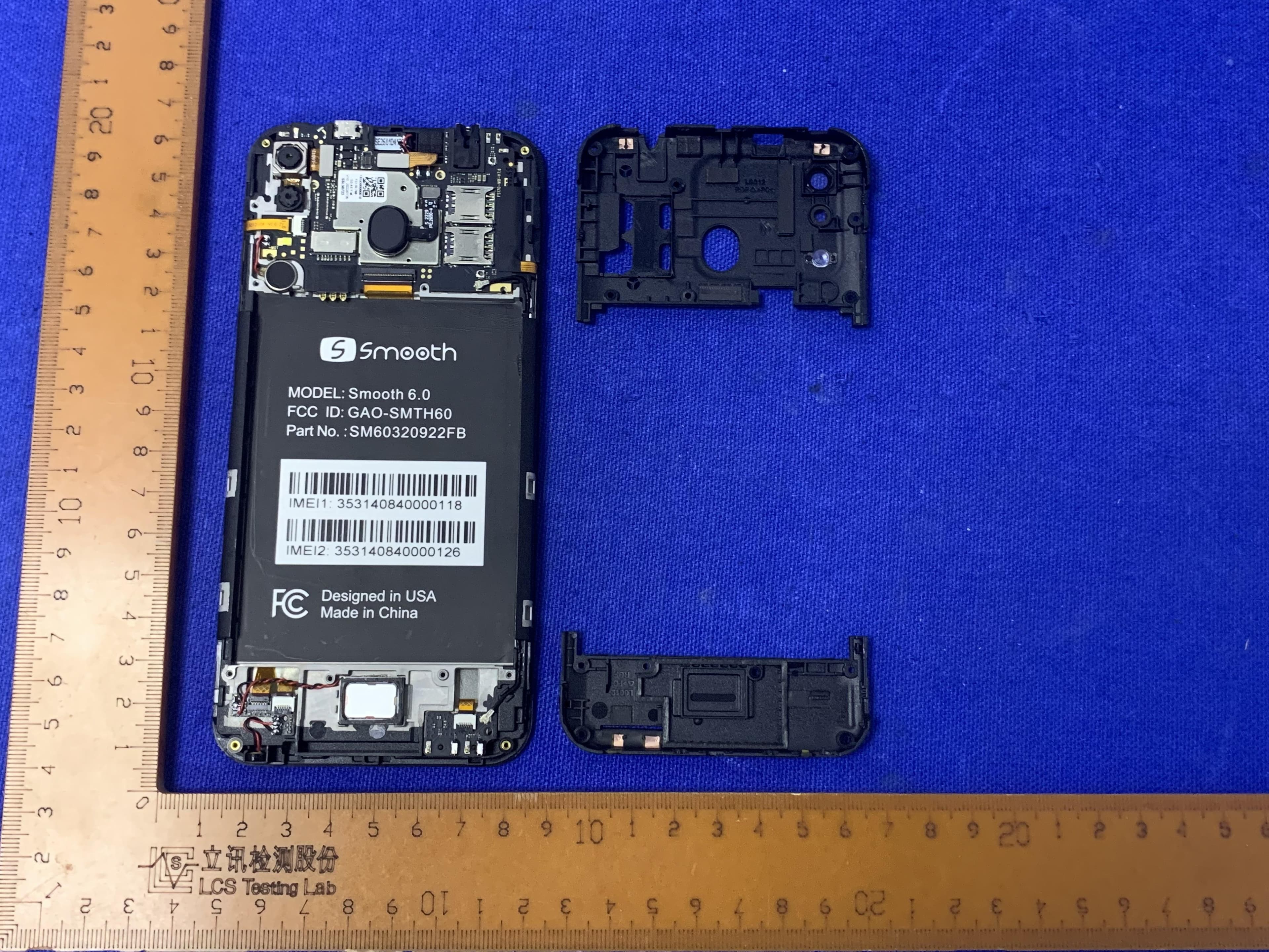
GAO-SMTH60
Oct 13, 2022Smart phone
Equipment Class
DSS - Part 15 Spread Spectrum Transmitter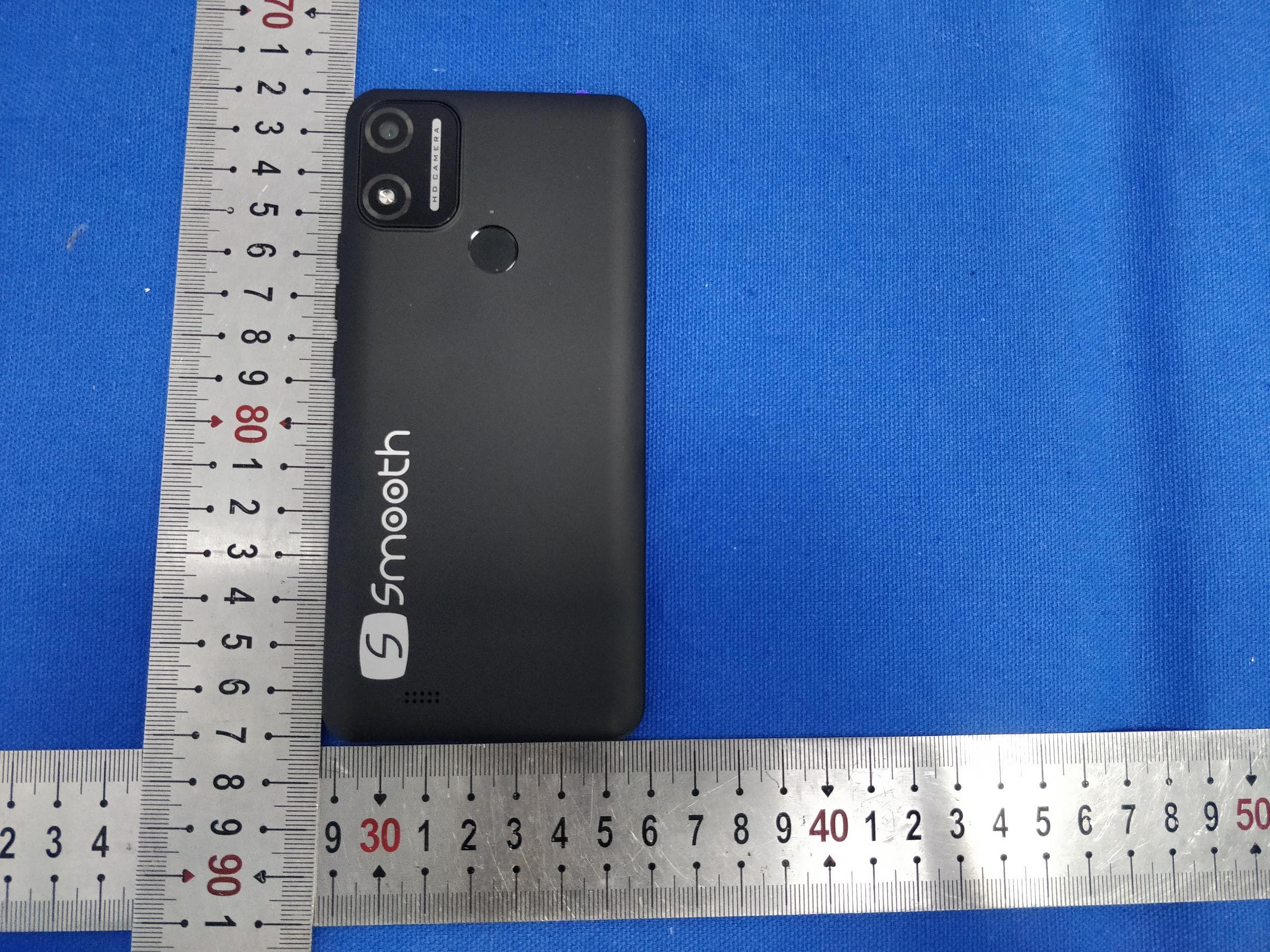
GAO-55MAX22
Jun 07, 2022Smart phone
Equipment Class
PCE - PCS Licensed Transmitter held to ear