GCYDNNNWDNNNW
Advanced Input Devices Inc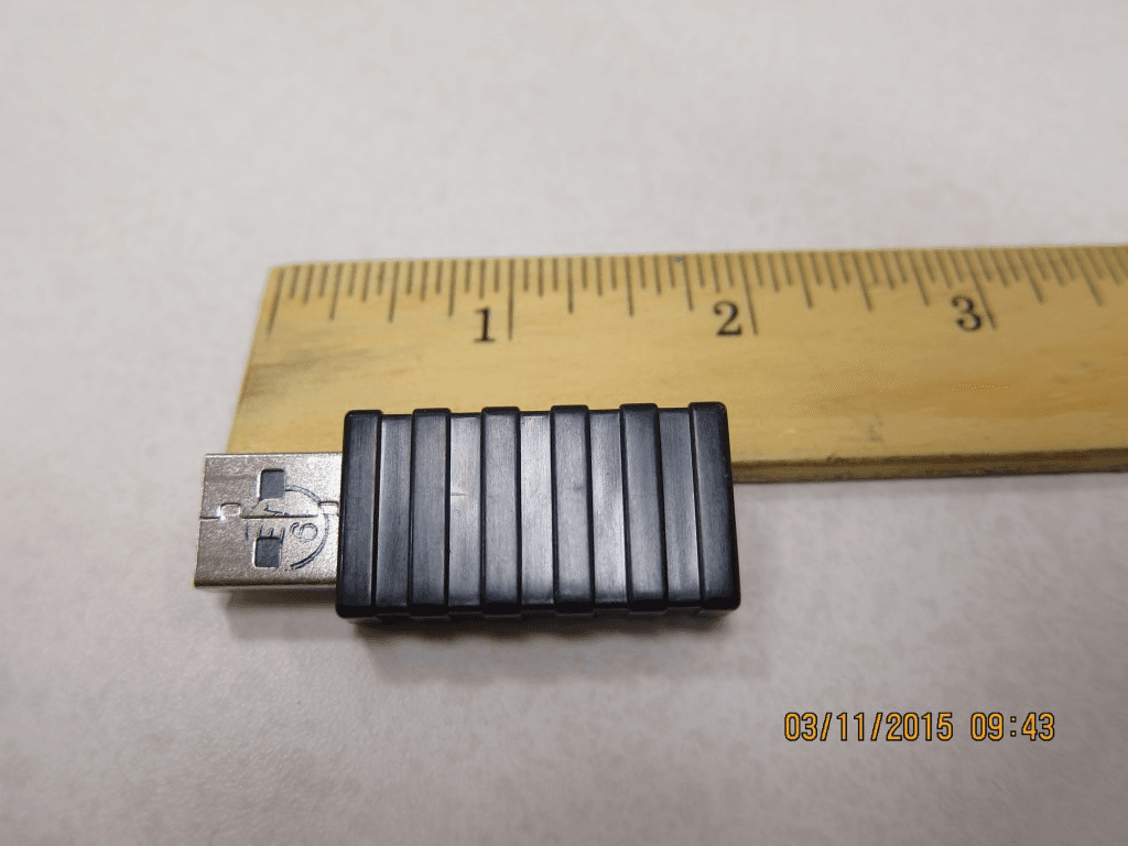
Click to zoom
Application Details
- Equipment Class
- DTS - Digital Transmission System
- Date of Grant
- Jun 03, 2015
- Application Purpose
- Original Equipment
- Date of Application
- Jun 03, 2015
- Equipment Note
- DNNNW
- Frequency Range
- 2402.00000000 - 2480.00000000
- Company
- Advanced Input Devices Inc
- Country
- United States
Documents & Files
Document Text
Text extracted from the exhibit documents filed with the FCC. Open a document above to read the original.
Users Manual
English Medigenic Wireless Keyboard ‐ Medical Keyboard Quick Start User Guide Connect the USB Dongle to any USB port on the computer. The USB driver software will begin to download automatically to your computer, and the status of this should show in a pop up window from your status bar in the bottom right portion of your screen. This should take no longer than one minute. The USB Dongle is bound to the keyboard at the factory, so no further action is required by the user for the two devices to communicate. While waiting for this to happen, turn the keyboard over and remove the battery cover located beneath the wide portion of the elastomeric cover. Remove the brown paper spacer located between the two batteries, and then replace the battery cover and elastomeric material to its proper place. When the batteries are first installed the keyboard will startup in clean mode, which is indicated by a light in the top left corner by the symbol. This tells you that the batteries are installed properly and providing enough power to the keyboard, and it also prevents inadvertent keystrokes while the keyboard is upside down for battery installation. This will turn itself off after a 30 second timer or can be turned off sooner by pressing the clean mode button under the icon. To clean the surface of the keyboard, press the to turn the keyboard off. The amber light by the icon will illuminate showing that the keys are disabled and it is now OK to clean the unit. Clean the keyboard with a hospital approved germicidal spray or wipe. If using a spray, wipe the surface of the keyboard with a cloth. Your mouse should also be cleaned at this time. After cleaning, push the Icon to turn the keyboard back on, at which time the LED will turn off. If you forget to restart the keyboard it will do so itself after 30 seconds. Additional sets of rear mounting feet in different sizes are provided to adjust the height and angle of the keyboard to match user preference. Simply select the desired set, move the adhesive backing and install over the existing feet. Deutsch Medigenic kabellose Tastatur ‐ Medizinische Tastatur – Kurzanleitung Verbinden Sie das USB Dongle mit einer beliebigen USB Schnittstelle auf ihrem PC. Der USB Driver beginnt automatisch mit dem Herunterladen und zeigt den Status in einem separaten Fenster an der Statuszeile rechts unten auf dem Monitor. Dies sollte nicht länger als eine Minute dauern. Der USB‐Dongle wird werkseitig an die Tastatur angeschlossen. Der Benutzer muss daher keine weiteren Maßnahmen für die Kommunikation der beiden Geräte untereinander ergreifen. Während Sie warten, bis die Software heruntergeladen ist, drehen Sie die Tastatur um und entfernen Sie den Deckel des Batteriefachs, der sich unterhalb des breiten Teilbereichs des elastomeren Schutzes befindet. Entfernen Sie das braune Papier, das sich zwischen den beiden Batterien befindet, schließen Sie den Batteriedeckel und setzen den elastomeren Schutz wieder ein. Sobald die Batterien zum ersten Mal aktiv sind, startet die Tastatur in den Reinigungsmodus, der in der oben linken Ecke gleich neben dem mit einer LED angezeigt wird. Es bestätigt, dass die Batterien richtig eingelegt sind und der Tastatur genügend Strom zur Verfügung steht. Es verhindert zusätzlich einen unbeabsichtigten Tastenanschlag während die Tastatur zum Batteriewechsel umgedreht wird. Dieser Modus schaltet sich automatisch nach 30 Sekunden aus oder kann früher deaktiviert werden, indem die Taste für Reinigungsmodus unter dem Symbol gedrückt wird. Um die Oberfläche der Tastatur zu desinfizieren, drücken Sie bitte das Symbol, wodurch die Tastatur deaktiviert wird. Die gelbe LED neben dem zeigt, dass die Tastatur jetzt deaktiviert ist und desinfiziert werden kann. Desinfizieren Sie die Tastatur mit einem für das Krankenhaus genehmigten keimtötenden Spray oder Tuch. Falls ein Spray benutzt wird, sollte die Oberfläche der Tastatur mit einem Tuch gereinigt werden. Die Maus sollte zur selben Zeit ebenfalls gereinigt werden. Nach der Desinfektion, drücken Sie auf das Symbol, um die Tastatur wieder zu aktivieren, zeitgleich erlischt die LED. Falls Sie vergessen, die Tastatur wieder zu aktivieren, schaltet sich diese nach 30 Sekunden automatisch wieder ein. Für die hinteren Füße werden zusätzliche Sets in verschiedenen Größen zur Verfügung gestellt, um Höhe und Winkel individuell einstellen zu können. Wählen Sie das gewünschte Set aus, entfernen Sie die Klebefolie und befestigen sie diese über den bestehenden Füßen. Francais Clavier sans fil Medigenic ‐ Guide de démarrage rapide du clavier médical Branchez la clé USB à un port USB de l’ordinateur. Le pilote USB sera automatiquement installé sur votre ordinateur. L’avancement de cette installation devrait s’afficher dans une fenêtre contextuelle de votre barre d’état, dans la partie inférieure droite de votre écran. Ce processus ne devrait pas durer plus d’une minute. La clé électronique USB est liée au clavier en usine, de sorte qu’aucune autre action n’est requise de la part de l’utilisateur pour que les deux appareils puissent communiquent entre eux. Pendant ce temps, retournez le clavier et enlevez le couvercle de pile situé sous la partie large du couvercle élastomère. Retirez le papier intercalaire marron situé entre les deux piles, puis replacez le couvercle de pile et le matériau élastomère. Quand les piles sont installées pour la première fois, le clavier démarre en mode de nettoyage, indiqué par un voyant dans le coin supérieur gauche situé à côté du symbole de . Cela vous indique que les piles sont correctement installées et alimentent suffisamment le clavier. Cela vous empêche également d’appuyer par inadvertance sur des touches pendant que le clavier est retourné pour insérer les piles. Ce voyant s’éteindra tout seul après 30 secondes. Vous pouvez également l’éteindre en appuyant sur la touche du mode de nettoyage . Pour nettoyer la surface du clavier, appuyez sur la touche pour éteindre le clavier. Le voya…
Text truncated - open the document above for the full version.
Cover Letter(s)
Interface Technologies Interface Technologies is a marketing name for Advanced Input Devices, Gamesman Ltd., LRE Medical GmbH, and Memtron Technologies - wholly owned subsidiaries of Esterline Technologies Corporation. COMPANY CONFIDENTIAL TR 1 of 1 2-Jun-15 Esterline Interface Technologies 600 West Wilbur Avenue Coeur d’Alene, ID 83815 Tel: 208-765-8000 Fax: 208-292-2271 www.esterline.com NYSE: ESL FCC Application Letter Featuring: ADVANCED INPUT, GAMESMAN, LRE MEDICAL, and MEMTRON Products Federal Communications Commission Authorization and Evaluation Division 7435 Oakland Mills Road Columbia, MD 21046 Subject: FCC Application Letter Model #: DNNNW, referred to as Medigenic K080 & K081 Keyboard Dongle in the test reports FCC ID: GCYDNNNW To Whom It May Concern: This letter is a request for original certification approval under FCC 15.247 for a wireless USB dongle for use with a wireless keyboard. Together, the units function as a wireless keyboard for any computer system with a USB port. The radio link between the keyboard and the dongle uses the 2.4GHz unlicensed band in a hybrid frequency-hopping design. A separate FCC application will be submitted simultaneously for the wireless keyboard. Best Regards Wayne Hash Reliability & Compliance Engineer
External Photos
K080/081 Dongle External photo
ID Label/Location Info
Proposed Label ITE Listed ITE Accessory File E173439 Model KNNNW FCC ID: GCYDNNNW IC: XXXXXX-YYYYYYYY This device complies with part 15 of the FCC rules. Operation is subject to the following two conditions: (1) This device may not cause harmful interference, and (2) this device must accept any interference received, including interference that may cause undesired operation. Assembled in USA Label Location The dongle is too small to be labeled. The lebel (above) will be printed in the User Manual as follows:
Internal Photos
K080/081 Dongle Internal photos
Operational Description
Antenna Information The antenna used with the K808/K081 dongle is a PCB trace intrnal to the USB dongle as shown in the figure below. It is not accessable to the user for modification meeting the requirement of 47 CFR 15.203. The design value for the antenna gain is 0.46dBi
RF Exposure Info
This report must not be used to claim product certification, approval, or endorsement by NVLAP, NIST, or any agency of the federal government of the United States of America. This Report may only be duplicated in its entirety Esterline (Advanced Input Devices) Medigenic DeskMini Wireless Keyboard and USB Dongle FCC 2.1093:2015 Report # ESTE0018.8 NVLAP Lab Code: 200881-0 CERTIFICATE OF EVALUATION 2014-12-10 Product compliance is the responsibility of the client; therefore, the tests and equipment modes of operation represented in this report were agreed upon by the client, prior to testing. The results of this test pertain only to the sample(s) tested. The specific description is noted in each of the individual sections of the test report supporting this certificate of test. Last Date of Test: February 16, 2015 Esterline (Advanced Input Devices) Model: Medigenic DeskMini Wireless Dongle Radio Equipment Testing Standards Specification Method FCC 2.1093:2015 447498 D01 General RF Exposure Guidance v05r02 Results Method Clause Test Description Applied Results Comments 4.3 General SAR test reduction and exclusion guidance Yes Pass Deviations From Test Standards None Approved By: Donald Facteau, IT Manager Report No. ESTE0018.82/7 REVISION HISTORY REV 2014.10.14 Revision Number Description Date Page Number 00 None Report No. ESTE0018.83/7 ACCREDITATIONS AND AUTHORIZATIONS REV 2014.10.08 United States FCC - Designated by the FCC as a Telecommunications Certification Body (TCB). Certification chambers, Open Area Test Sites, and conducted measurement facilities are listed with the FCC. A2LA - Accredited by A2LA to ISO / IEC Guide 65 as a product certifier. This allows Northwest EMC to certify transmitters to FCC and IC specifications. NVLAP - Each laboratory is accredited by NVLAP to ISO 17025 Canada IC - Recognized by Industry Canada as a Certification Body (CB). Certification chambers and Open Area Test Sites are filed with IC. European Union European Commission – Validated by the European Commission as a Conformity Assessment Body (CAB) under the EMC directive and as a Notified Body under the R&TTE Directive. Australia/New Zealand ACMA - Recognized by ACMA as a CAB for the acceptance of test data. Korea MSIP / RRA - Recognized by KCC’s RRA as a CAB for the acceptance of test data. Japan VCCI - Associate Member of the VCCI. Conducted and radiated measurement facilities are registered. Taiwan BSMI – Recognized by BSMI as a CAB for the acceptance of test data. NCC - Recognized by NCC as a CAB for the acceptance of test data. Singapore IDA – Recognized by IDA as a CAB for the acceptance of test data. Israel MOC – Recognized by MOC as a CAB for the acceptance of test data. Hong Kong OFTA – Recognized by OFTA as a CAB for the acceptance of test data. Vietnam MIC – Recognized by MIC as a CAB for the acceptance of test data. SCOPE For details on the Scopes of our Accreditations, please visit: http://www.nwemc.com/accreditations/ Report No. ESTE0018.84/7 FACILITIES REV 2015.1.05 California Labs OC01-13 41 Tesla Irvine, CA 92618 (949) 861-8918 Minnesota Labs MN01-08, MN10 9349 W Broadway Ave. Brooklyn Park, MN 55445 (612)-638-5136 New York Labs NY01-04 4939 Jordan Rd. Elbridge, NY 13060 (315) 685-0796 Oregon Labs EV01-12 22975 NW Evergreen Pkwy Hillsboro, OR 97124 (503) 844-4066 Texas Labs TX01-09 3801 E Plano Pkwy Plano, TX 75074 (469) 304-5255 Washington Labs NC01-05 19201 120 th Ave NE Bothell, WA 9801 (425)984-6600 NVLAP NVLAP Lab Code: 200676-0 NVLAP Lab Code: 200881-0 NVLAP Lab Code: 200761-0 NVLAP Lab Code: 200630-0 NVLAP Lab Code:201049-0 NVLAP Lab Code: 200629-0 Industry Canada 2834B-1, 2834B-3 2834E-1 N/A 2834D-1, 2834D-2 2834G-1 2834F-1 BSMI SL2-IN-E-1154R SL2-IN-E-1152R N/A SL2-IN-E-1017 SL2-IN-E-1158R SL2-IN-E-1153R VCCI A-0029 A-0109 N/A A-0108 A-0201 A-0110 Report No. ESTE0018.85/7 PRODUCT DESCRIPTION 2014-12-10 Client and Equipment Under Test (EUT) Information Company Name: Esterline (Advanced Input Devices) Address: 600 W. Wilbur Avenue City, State, Zip: Coeur d’Alene, ID 83815 Test Requested By: Wayne Hash Model: Medigenic DeskMini Wireless Dongle Evaluation Date: February 16, 2015 Information Provided by the Party Requesting the Test Functional Description of the EUT: Wireless Dongle operating as a hybrid radio in the 2.4 GHz band under FCC 15.247. Testing Objective: To demonstrate compliance with FCC requirements for RF exposure for 2.1093 portable devices. Report No. ESTE0018.86/7 SAR TEST EXCLUSION WTD.2014.12.17 OVERVIEW The device is excluded from SAR evaluation and therefore deemed compliant with FCC RF exposure requirements as described below: COMPLIANCE WITH FCC KDB 447498 D01 General RF Exposure Guidance v05r02 KDB 447498 D01 General RF Exposure Guidance v05r02, Section 4.3.1 “The 1-g and 10-g SAR test exclusion thresholds for 100 MHz to 6 GHz at test separation distances ≤ 50 mm are determined by: [(max. power of channel, including tune-up tolerance, mW)/(min. test separation distance, mm)] · [√f(GHz)] ≤ 3.0 for 1-g SAR and ≤ 7.5 for 10-g extremity SAR, where f(GHz) is the RF channel transmit frequency in GHz Power and distance are rounded to the nearest mW and mm before calculation The result is rounded to one decimal place for comparison 3.0 and 7.5 are referred to as the numeric thresholds in the step 2 below The test exclusions are applicable only when the minimum test separation distance is ≤ 50 mm and for transmission frequencies between 100 MHz and 6 GHz. When the minimum test separation distance is < 5 mm, a distance of 5 mm according to 5) in section 4.1 is applied to determine SAR test exclusion.” METHOD OF EVALUATION The SAR Test Exclusion Threshold is summarized in the following table: The device has a maximum output power of 0.14015 mW at 2480 MHz. The closest spacing of the antenna to the user’s torso is 5 mm. The table below shows the results of the calculation. The value of 0.014 is well below the exclusion threshold of 3.0, therefore the unit is exc…
Text truncated - open the document above for the full version.
Test Report
This report must not be used to claim product certification, approval, or endorsement by NVLAP, NIST, or any agency of the federal government of the United States of America. This Report may only be duplicated in its entirety Esterline (Advanced Input Devices) Medigenic K080/K081 Wireless USB Dongle FCC 15.247:2015 Report # ESTE0018.2 NVLAP Lab Code: 200630-0 CERTIFICATE OF TEST 2014-12-10 Product compliance is the responsibility of the client; therefore, the tests and equipment modes of operation represented in this report were agreed upon by the client, prior to testing. The results of this test pertain only to the sample(s) tested. The specific description is noted in each of the individual sections of the test report supporting this certificate of test. Last Date of Test: February 06, 2015 Esterline (Advanced Input Devices) Model: Medigenic K080/K081 Wireless USB Dongle Radio Equipment Testing Standards Specification Method FCC 15.247:2014 ANSI C63.10:2009 DA 00-705:2000 Results Method Clause Test Description Applied Results Comments 6.2 AC Powerline Conducted Emissions Yes Pass 6.5, 6.6 Spurious Radiated Emissions Yes Pass 6.7 Spurious Conducted Emissions Yes Pass 6.9.1 Occupied Bandwidth Yes Pass 6.10.1 Output Power Yes Pass 6.11.2 Power Spectral Density Yes Pass 7.5 Duty Cycle Yes N/A Characterization of radio operation. 7.7.2 Channel Spacing Yes Pass 7.7.3 Number of Hopping Frequencies Yes N/A No limit for a Hybrid radio. Required for Dwell Time measurement. 7.7.4 Dwell Time Yes Pass 7.7.9 Band Edge Compliance Yes Pass Deviations From Test Standards None Approved By: Kyle Holgate, Operations Manager Report No. ESTE0018.22/61 REVISION HISTORY REV 2014.10.14 Revision Number Description Date Page Number 00 None Report No. ESTE0018.23/61 ACCREDITATIONS AND AUTHORIZATIONS REV 2015.2.10 United States FCC - Designated by the FCC as a Telecommunications Certification Body (TCB). Certification chambers, Open Area Test Sites, and conducted measurement facilities are listed with the FCC. A2LA - Accredited by A2LA to ISO / IEC 17065 as a product certifier. This allows Northwest EMC to certify transmitters to FCC and IC specifications. NVLAP - Each laboratory is accredited by NVLAP to ISO 17025 Canada IC - Recognized by Industry Canada as a Certification Body (CB). Certification chambers and Open Area Test Sites are filed with IC. European Union European Commission – Validated by the European Commission as a Conformity Assessment Body (CAB) under the EMC directive and as a Notified Body under the R&TTE Directive. Australia/New Zealand ACMA - Recognized by ACMA as a CAB for the acceptance of test data. Korea MSIP / RRA - Recognized by KCC’s RRA as a CAB for the acceptance of test data. Japan VCCI - Associate Member of the VCCI. Conducted and radiated measurement facilities are registered. Taiwan BSMI – Recognized by BSMI as a CAB for the acceptance of test data. NCC - Recognized by NCC as a CAB for the acceptance of test data. Singapore IDA – Recognized by IDA as a CAB for the acceptance of test data. Israel MOC – Recognized by MOC as a CAB for the acceptance of test data. Hong Kong OFTA – Recognized by OFTA as a CAB for the acceptance of test data. Vietnam MIC – Recognized by MIC as a CAB for the acceptance of test data. SCOPE For details on the Scopes of our Accreditations, please visit: http://www.nwemc.com/accreditations/ http://gsi.nist.gov/global/docs/cabs/designations.html Report No. ESTE0018.24/61 MEASUREMENT UNCERTAINTY TMU.2014.12.03 Measurement Uncertainty When a measurement is made, the result will be different from the true or theoretically correct value. The difference is the result of tolerances in the measurement system that cannot be completely eliminated. To the extent that technology allows us, it has been our aim to minimize this error. Measurement uncertainty is a statistical expression of measurement error qualified by a probability distribution. A measurement uncertainty estimation has been performed for each test per our internal quality document WP 342. The estimation is used to compare the measured result with its "true" or theoretically correct value. The expanded measurement uncertainty (K=2) for each test is on each data sheet. Our measurement data meets or exceeds the measurement uncertainty requirements of the applicable specification; therefore, the test data can be compared directly to the specification limit to determine compliance. The calculations for estimating measurement uncertainty are based upon ETSI TR 100 028 (or CISPR 16-4-2 as applicable), and are available upon request. The following table represents the Measurement Uncertainty (MU) budgets for each of the tests that may be contained in this report. Test + MU - MU Frequency Accuracy (Hz) 0.0007% -0.0007% Amplitude Accuracy (dB) 1.2 dB -1.2 dB Conducted Power (dB) 0.3 dB -0.3 dB Radiated Power via Substitution (dB) 0.7 dB -0.7 dB Temperature (degrees C) 0.7°C -0.7°C Humidity (% RH) 2.5% RH -2.5% RH Voltage (AC) 1.0% -1.0% Voltage (DC) 0.7% -0.7% Field Strength (dB) 5.2 dB -5.2 dB AC Powerline Conducted Emissions (dB) 2.9 dB -2.9 dB Report No. ESTE0018.25/61 FACILITIES REV 2015.2.10 California Labs OC01-13 41 Tesla Irvine, CA 92618 (949) 861-8918 Minnesota Labs MN01-08, MN10 9349 W Broadway Ave. Brooklyn Park, MN 55445 (612)-638-5136 New York Labs NY01-04 4939 Jordan Rd. Elbridge, NY 13060 (315) 685-0796 Oregon Labs EV01-12 22975 NW Evergreen Pkwy Hillsboro, OR 97124 (503) 844-4066 Texas Labs TX01-09 3801 E Plano Pkwy Plano, TX 75074 (469) 304-5255 Washington Labs NC01-05 19201 120 th Ave NE Bothell, WA 9801 (425)984-6600 NVLAP NVLAP Lab Code: 200676-0 NVLAP Lab Code: 200881-0 NVLAP Lab Code: 200761-0 NVLAP Lab Code: 200630-0 NVLAP Lab Code:201049-0 NVLAP Lab Code: 200629-0 Industry Canada 2834B-1, 2834B-3 2834E-1 N/A 2834D-1, 2834D-2 2834G-1 2834F-1 BSMI SL2-IN-E-1154R SL2-IN-E-1152R N/A SL2-IN-E-1017 SL2-IN-E-1158R SL2-IN-E-1153R VCCI A-0029 A-0109 N/A A-0108 A-0201 A-0110 Recognized Phase I CAB fo…
Text truncated - open the document above for the full version.
Test Setup Photos
AC POWERLINE CONDUCTED EMISSIONS WTD.2015.01.28 PSA-ESCI 2015.01.16, EmiR5 2014.11.19.2 AC POWERLINE CONDUCTED EMISSIONS WTD.2015.01.28 PSA-ESCI 2015.01.16, EmiR5 2014.11.19.2 photo Dongle SRE 001.JPG Dongle SRE 002.JPG SPURIOUS RADIATED EMISSIONS PSA-ESCI 2015.01.16 Report No. ESTE0018.22/13 photo Dongle SRE 003.JPG Dongle SRE 004.JPG SPURIOUS RADIATED EMISSIONS PSA-ESCI 2015.01.16 Report No. ESTE0018.23/13 photo Dongle SRE 005.JPG SPURIOUS RADIATED EMISSIONS PSA-ESCI 2015.01.16 Report No. ESTE0018.24/13 XMit 2015.01.14 EV06 Direct Connect Dongle 001.JPG EV06 Direct Connect Dongle 002.JPG SPURIOUS CONDUCTED EMISSIONS Report No. ESTE0018.25/13 XMit 2015.01.14 EV06 Direct Connect Dongle 001.JPG EV06 Direct Connect Dongle 002.JPG OCCUPIED BANDWIDTH Report No. ESTE0018.26/13 XMit 2015.01.14 EV06 Direct Connect Dongle 001.JPG EV06 Direct Connect Dongle 002.JPG OUTPUT POWER Report No. ESTE0018.27/13 XMit 2015.01.14 EV06 Direct Connect Dongle 001.JPG EV06 Direct Connect Dongle 002.JPG POWER SPECTRAL DENSITY Report No. ESTE0018.28/13 XMit 2015.01.14 EV06 Direct Connect Dongle 001.JPG EV06 Direct Connect Dongle 002.JPG CHANNEL SPACING Report No. ESTE0018.29/13 XMit 2015.01.14 EV06 Direct Connect Dongle 001.JPG EV06 Direct Connect Dongle 002.JPG NUMBER OF HOPPING FREQUENCIES Report No. ESTE0018.210/13 XMit 2015.01.14 EV06 Direct Connect 825.JPG EV06 Direct Connect 826.JPG DWELL TIME Report No. ESTE0018.211/13 XMit 2015.01.14 EV06 Direct Connect Dongle 001.JPG EV06 Direct Connect Dongle 002.JPG BAND EDGE COMPLIANCE Report No. ESTE0018.212/13
Contact Information
Applicant
Dennis Staver(President of Esterline Interface Technologies)
Test Firm
Northwest EMC, Inc.Greg Kiemel
Technical Specifications
| # | Rule Parts | Frequency Range | Power Output |
|---|---|---|---|
| 1 | 15C | 2.40 GHz - 2.48 GHz | 140.00 µW |
Other Applications from Advanced Input Devices Inc
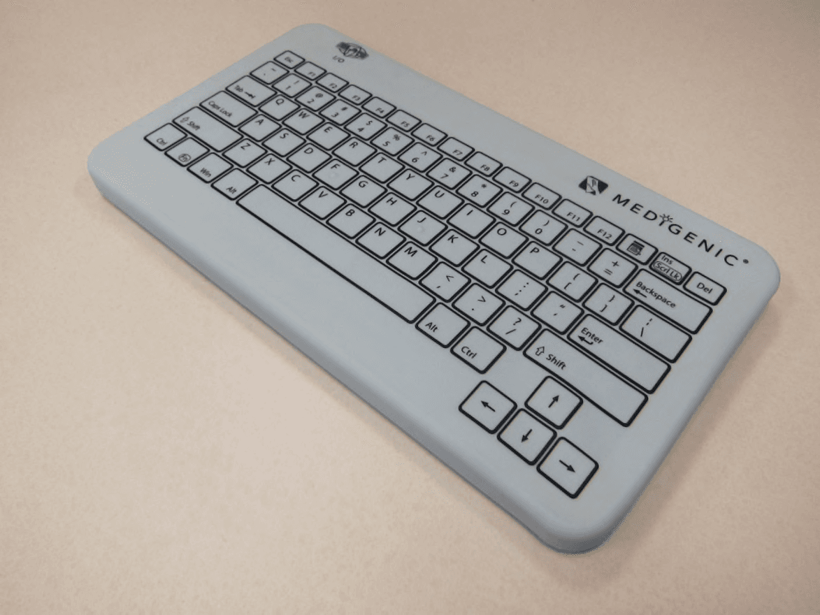
GCYKNNNW
Jun 03, 2015KNNNW
Equipment Class
DTS - Digital Transmission SystemGCYPKD-101
Aug 12, 1990Keyboard
Equipment Class
JBP - Part 15 Class B Computing Device PeripheralGCYEKT-101
Oct 04, 1989Keyboard
Equipment Class
JBP - Part 15 Class B Computing Device Peripheral