GFB01036Lane Controller
Micro Industries Inc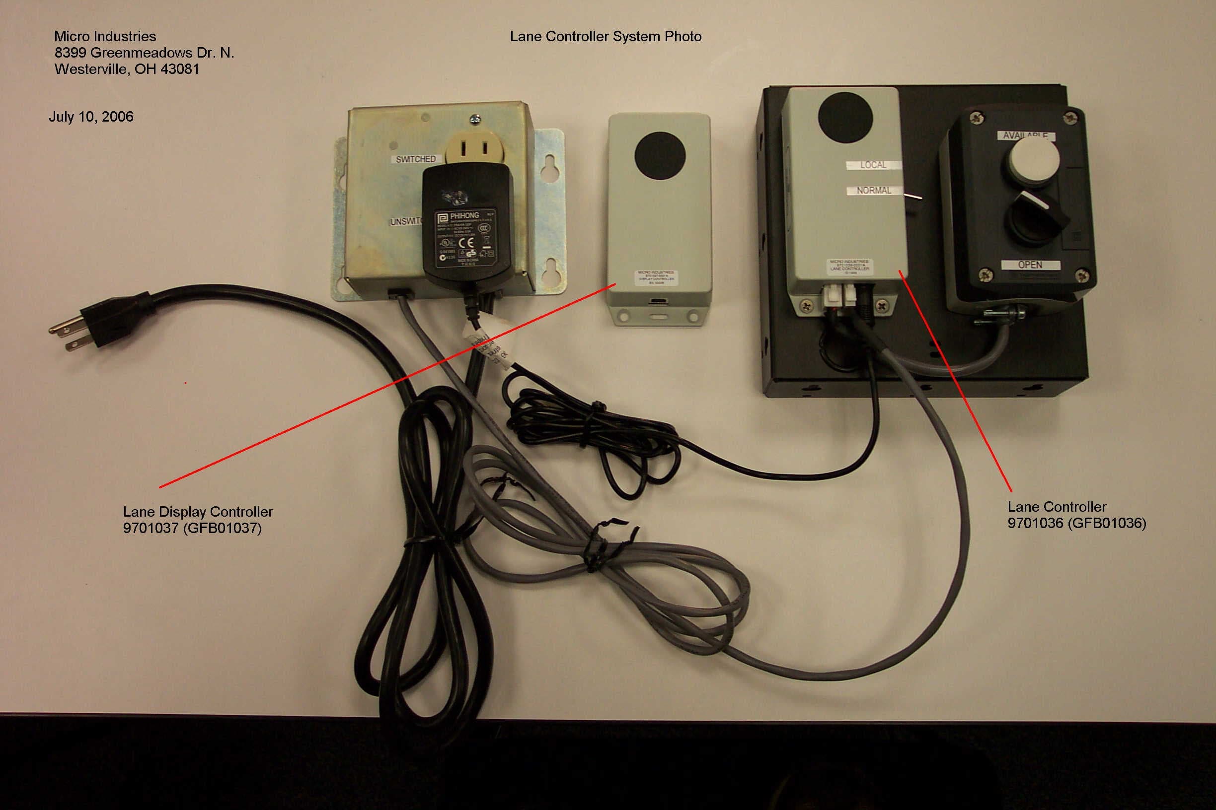
Click to zoom
Application Details
- Equipment Class
- DTS - Digital Transmission System
- Date of Grant
- Aug 02, 2006
- Application Purpose
- Original Equipment
- Date of Application
- Aug 02, 2006
- Equipment Note
- Lane Controller
- Frequency Range
- 2474.90000000 - 2474.90000000
- Company
- Micro Industries Inc
- Country
- United States
Documents & Files
Document Text
Text extracted from the exhibit documents filed with the FCC. Open a document above to read the original.
Users Manual
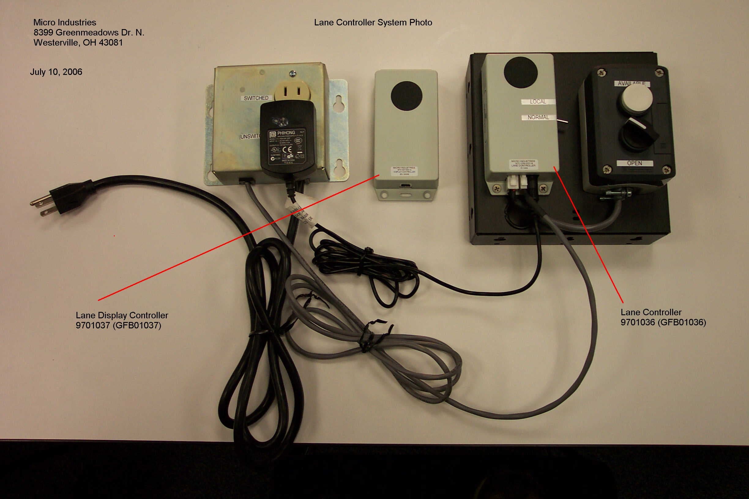
Micro Industries Installation and User Guide Lane Controller & Lane Display Controller 9701036 9701037 Prepared By: Dave Hildebrand Revision Number: V0.2 Date: 6-13-06 Revision History: V0.1 Created V0.2 Added modification statement 2 Lane Controller Installation and User Guide 1. Mount the switch box bracket assembly using the supplied #8 screws in either 5/8” or 1” length or other appropriate screws or anchors for the specific location. At least 4 screws are needed to secure the bracket, 2 in the front keyholes and 2 more in the rear holes of the mounting side. 2. Locate the relay box so that the lane light may be plugged in and within reach of the switch box bracket assembly (about 5’). Mount the relay box assembly using 4 of the supplied #8 screws in either 5/8” or 1” length or other appropriate screws or anchors for the specific location. 3. Route the gray relay cable from the relay box to the switch box bracket assembly. Bring the cable through the grommet near the bottom of the bracket and plug it into the 2 pin connector at the bottom of the lane controller module observing the polarity of the plug. 4. Plug the supplied wall-mount power supply into the UNSWITCHED outlet of the relay box assembly. NOTE: The supplied power supply must be used since it is an LPS (Limited Power Source) type of power supply. This will protect the operator and equipment from excess current. The power supply is manufactured by Phihong and is Model PSA15R-120P. 5. Route the power supply cable to the switch box assembly. Bring the cable through the grommet near the bottom of the of the bracket and plug it into the power supply connector of the lane controller module. 6. Plug the end of the power cord from the relay box into a standard 120VAC outlet. 7. Plug the lane light into the switched outlet of the relay box assembly. 8. Locate the LOCAL/NORMAL switch on the side of the lane controller module and set it to the NORMAL position (down position). 9. The black selector switch will select the lane open position when in the locked position (about 11:00 position). This will signal the kiosk that the lane is now open. The lane light will turn on. 10. The white pushbutton when pushed will signal the kiosk that the lane is available to a customer. The kiosk will set the lane light to flash for about 8 seconds to guide a customer to that lane. 11. The LOCAL/NORMAL switch may be used to control the lane light without the kiosk running by setting the switch into the LOCAL position (up position). This will provide local control of the lane light. Operation of the button and selector switch will remain the same in the local position, without any interaction from the kiosk. This device complies with part 15 of the FCC Rules. Operation of the device is subject to the two following conditions: (1) This device may not cause harmful interference, and (2) This device must accept any interference received, including interference that may cause undesired operation. Lane Controller FCC ID: GFB01036 Lane Display Controller FCC ID: GFB01037 NOTE: Any changes or modifications made to this device which are not expressly approved by Micro Industries could void the user's authority to operate this equipment.
ID Label/Location Info
SCALE 1:1 SCALE 2:1
RF Exposure Info
Prediction of MPE limit at a given distance Equation from page 18 of OET Bulletin 65, Edition 97-01 where:S = power density P = power input to the antenna G = power gain of the antenna in the direction of interest relative to an isotropic radiator R = distance to the center of radiation of the antenna Lane Controller for Micro Industries Maximum peak output power at antenna input terminal:-16.0(dBm) Maximum peak output power at antenna input terminal:0.000(W) Antenna gain(typical):0.40(dBi) Maximum antenna gain:1.10(numeric) Prediction distance:20.00(cm) Prediction frequency:824.20(MHz) MPE limit for uncontrolled exposure at prediction frequency:1.00(mW/cm^2) Power density at prediction frequency:0.000005(mW/cm^2) Maximum allowable antenna gain:83.01(dBi) Margin of Compliance:52.61dB 2 4R PG S π = Therefore the power density at 20 cm = 0.0000005 W/m 2
Test Report
Nemko USA, Inc. 11696 Sorrento Valley Rd., Suite F San Diego, CA 92121-1024 Phone (858) 755-5525 Fax (858) 452-1810 CERTIFICATION REPORT PART 15.247, SUBPART C DECLARATION OF CONFORMANCE PROCEDURES TEST REPORT For The Point of Sale Availability Indicator Model: Lane Controller 9701036 FCC ID#: GFB01036 PREPARED FOR: Micro Industries 8399 Greenmeadows Dr. North Westerville, OH 43081 PREPARED ON JUNE 22, 2006 R EPORT NUMBER: 2006 060348-FCC1 P ROJECT NUMBER: 26-348-MIC-R1 Total Pages: 39 Nemko USA, Inc. 11696 Sorrento Valley Road, Suite F, San Diego, CA 92121 Phone (858) 755-5525 Fax (858) 452-1810 DATE DOCUMENT NAME DOCUMENT # PAGE June 22, 2006 Micro Industries Lane Director/Control FCC Test Report FCC ID# GFB01036 2006 060348-FCC1 2 of 39 DOCUMENT HISTORY REVISION DATE COMMENTS - 6-22-06 Prepared By: A. Laudani - 6-22-06 Initial Release: M. Krumweide NOTE: Nemko USA, Inc. hereby makes the following statements so as to conform to the Subclause 5.10 Requirements of ISO/IEC 17025 "General Criteria For the Competence Of Testing and Calibration Laboratories": o The unit described in this report was received at Nemko USA, Inc.'s facilities on May 22, 2006. Testing was performed on the unit described in this report on June 2, 2006. o The Test Results reported herein apply only to the Unit actually tested, and to substantially identical Units. o This report does not imply the endorsement of the Federal Communications Commission (FCC), NVLAP or any other government agency. This Report is the property of Nemko USA, Inc., and shall not be reproduced, except in full, without prior written approval of Nemko USA, Inc. However, all ownership rights are hereby returned unconditionally to Micro Industries, and approval is hereby granted to Micro Industries and its employees and agents to reproduce all or part of this report for any legitimate business purpose without further reference to Nemko USA, Inc. Nemko USA, Inc. 11696 Sorrento Valley Road, Suite F, San Diego, CA 92121 Phone (858) 755-5525 Fax (858) 452-1810 DATE DOCUMENT NAME DOCUMENT # PAGE June 22, 2006 Micro Industries Lane Director/Control FCC Test Report FCC ID# GFB01036 2006 060348-FCC1 3 of 39 TABLE OF CONTENTS DOCUMENT HISTORY .................................................................................................................................. 2 CERTIFICATION ............................................................................................................................................. 4 1. ADMINISTRATIVE DATA AND TEST SUMMARY ......................................................................... 5 1.1. ADMINISTRATIVE DATA............................................................................................................................ 5 2. SYSTEM CONFIGURATION ................................................................................................................ 6 2.1. SYSTEM COMPONENTS AND POWER CABLES............................................................................................. 6 2.2. DEVICE INTERCONNECTION AND I/O CABLES........................................................................................... 6 3. DESCRIPTION OF TEST SITE AND EQUIPMENT .......................................................................... 7 3.1. DESCRIPTION OF TEST SITE....................................................................................................................... 7 4. DESCRIPTION OF TESTING METHODS .......................................................................................... 8 4.1. INTRODUCTION......................................................................................................................................... 8 4.2. CONFIGURATION AND METHODS OF MEASUREMENTS FOR CONDUCTED EMISSIONS............................... 10 4.3. CONFIGURATION AND METHODS OF MEASUREMENTS FOR FREQUENCY IDENTIFICATION....................... 12 4.4. CONFIGURATION AND METHODS OF MEASUREMENTS FOR RADIATED EMISSIONS.................................. 14 4.5. OPERATION IN THE 15.247 BANDS........................................................................................................... 16 5. TEST RESULTS ..................................................................................................................................... 17 5.1. CONDUCTED EMISSIONS TEST DATA....................................................................................................... 17 5.2. STANDBY MODE...................................................................................................................................... 18 5.3 RADIATED EMISSIONS TEST DATA – ....................................................................................................... 20 5.3. CFR 47 PART 15C §15.247 TEST RESULTS............................................................................................. 22 5.4. DUTY CYCLE........................................................................................................................................... 23 5.5. 6 DB BANDWIDTH................................................................................................................................... 24 5.6. BAND EDGE LOW.................................................................................................................................... 25 5.7. BAND EDGE HIGH................................................................................................................................... 26 5.8. PEAK POWER........................................................................................................................................... 27 5.9. PEAK POWER DENSITY............................................................................................................................ 28 5.10. RADIATED SPURIOUS.......................................................................................................................... …
Text truncated - open the document above for the full version.
Contact Information
Applicant
Michael Curran Chief Executive Officer
Technical Contact
Micro Industries CorporationJoseph A Colecchi
[email protected]740-548-1825
8399 Greenmeadows Dr. N. · Westerville, Ohio · United States
Non-Technical Contact
Micro Industries CorporationJoseph A Colecchi
[email protected]740-548-1825
Test Firm
Nemko USA, Inc.Rhonda Saxon
Technical Specifications
| # | Rule Parts | Frequency Range | Power Output |
|---|---|---|---|
| 1 | 15C | 2.47 GHz - 2.47 GHz | 25.00 µW |
Other Applications from Micro Industries Inc
GFB01037
Aug 02, 2006Lane Display Controller
Equipment Class
DTS - Digital Transmission SystemGFB9584330A
Dec 15, 1996JBC - Part 15 Class B Computing Device/Personal Computer
Equipment Class
JBC - Part 15 Class B Computing Device/Personal ComputerGFB9584500A
Dec 15, 1996JBC - Part 15 Class B Computing Device/Personal Computer
Equipment Class
JBC - Part 15 Class B Computing Device/Personal Computer