GKXKDR510Ramp Test Transmitter
JcAIR Incorporated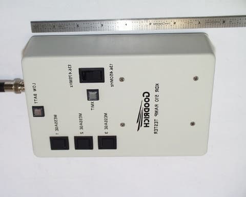
Click to zoom
Application Details
- Equipment Class
- TNB - Licensed Non-Broadcast Station Transmitter
- Date of Grant
- Oct 07, 2002
- Application Purpose
- Original Equipment
- Date of Application
- Oct 07, 2002
- Equipment Note
- Ramp Test Transmitter
- Frequency Range
- 136.45000000 - 136.47500000
- Company
- JcAIR Incorporated
- Country
- United States
Documents & Files
Document Text
Text extracted from the exhibit documents filed with the FCC. Open a document above to read the original.
Users Manual
FIS-B Ramp Tester Page 1of 15 Operator Manual FIS-B Ramp Tester For The KMD 540/KDR 510 FIS-B Avionics Display System FIS-B Ramp Tester Page 2of 15 Author: Robert M. Groh, Honeywell International Inc., Olathe, KS. 66061 File: C:\RMG_Documents\RampTester\Ramp Tester Operators Manual.doc Word Processor: Microsoft Office 97 This document and all information contained herein are the property of Honeywell International Inc, are provided in confidence, and may not be used, duplicated or disclosed to a third party, in whole or in part, without prior written permission from Honeywell International Inc, Copyright 2002 Honeywell International Inc, All rights reserved. Revision Table RevDateAuthorComment 1.0January 22, 2002RMGOriginal Draft 2.0January 24, 2002RMGAdded more photographs and information on changing frequency, etc. 2.1January 25, 2002RMGAdded ‘Range Check’ section Table Of Contents 1 CONTENTS AND SETUP.......................................................................................................................................3 1.1A SSEMBLING T HE R AMP T ESTER ................................................................................................... 3 1.2F RONT P ANEL C ONTROLS ............................................................................................................... 3 2 USING THE RAMP TESTER.................................................................................................................................4 2.1S HORT C OURSE IN O PERATING THE KMD 540 .............................................................................. 4 2.1.1 Accessing The Weather Display Page .......................................................................................................4 2.1.2 Accessing the FIS DATA page..................................................................................................................5 2.2C ONFIGURE THE KMD 540/KDR 510 SYSTEM .............................................................................. 5 2.3T RANSMIT A T EST M ESSAGE ......................................................................................................... 6 2.4I NTERPRET T HE R ESULTS ............................................................................................................... 6 2.4.1 ‘Lightning Bolt’ on Tower Symbol ...........................................................................................................6 2.4.2 APDU Counter on FIS DATA page ..........................................................................................................6 2.4.3 Date and Time on FIS DATA page ...........................................................................................................6 2.4.4 APDU Type on FIS DATA page ...............................................................................................................6 2.5G ROUND R ANGE C HECK ................................................................................................................. 6 3 MESSAGE 1: METAR.............................................................................................................................................7 4 MESSAGE 2: <TBD>.............................................................................................................................................14 5 MESSAGE 3: <TBD>.............................................................................................................................................14 6 ROUTINE MAINTENANCE ................................................................................................................................15 6.1B ATTERY R EPLACEMENT ............................................................................................................. 15 List of Figures Figure 1 Controls and Connectors .................................................................................................................................3 Figure 2 FIS DATA Page .............................................................................................................................................5 Figure 3 Interior View Showing Battery Locations.....................................................................................................15 FIS-B Ramp Tester Page 3of 15 1 Contents And Setup The Ramp Tester system includes the following items: 1. Ramp Tester Electronics Assembly 2. Plug In antenna assembly (BNC connector) 3. External Power Supply <Not provided with prototype units> 4. This Operators Manual 1.1 Assembling The Ramp Tester Remove the Ramp Test Electronics Assembly from the shipping package and plug in the supplied antenna. The Ramp Tester (RT) is now ready to use. Note: the prototype unit(s) are shipped with the alkaline batteries already connected. 1.2 Front Panel Controls Antenna Data Message 1 Message 2 Message 3 XMIT LOW BAT Frequency Switch External PS Figure 1 Controls and Connectors FIS-B Ramp Tester Page 4of 15 2 Using The Ramp Tester Using the Ramp Tester to ground test a FIS-B installation typically consists of several steps: 1. Power on the KMD 540/KDR 510 system and configure the KMD 540 display 2. While watching the KMD 540 display, transmit a message from the Ramp Tester by pressing one of the ‘Message’ buttons. 3. Interpret the results. During the test process, please refer to the KDR 510 and KMD 540 manuals (Install and Operations) for additional details which are not covered here. 2.1 Short Course in Operating the KMD 540 The following is a quick summary on accessing some of the pertinent pages on the KMD 540. Please refer to the KMD 540 manual for more detail. 2.1.1 Accessing The Weather Display Page The ‘Weather Display Page’ displays the graphical weather as well as the text based weather products. To access the ‘Weather Display Page, press the [WX] key on the front of the KMD 540. Each time you press the [WX] key, you will bring up, alternately, a different weather pro…
Text truncated - open the document above for the full version.
Cover Letter(s)
October 3, 2002 Timco Engineering Inc. 849 NW State Road 45 Newberry, FL 32669 Telephone 888.472.2424 Fax 352.472.2030 Applicant: JcAIR Incorporated 400 New Century Parkway New Century, KS 66031-0009 FRN 0007 7540 96 Re: Confidentiality of schematics, block diagrams and operational description. Equipment: Part 87 Aviation transmitter FCC ID: GKX KDR510 Gentlemen: It is requested that the information contained in the block diagrams, operational description and schematics of the application be held confidential per Section 0.459. Please use this information in obtaining a grant of certification for the transmitter, for use in the aviation services, model number KDR510RT. In support of this request, we submit the following: 1. Identification of the specific information for which confidential treatment is sought: The materials set fourth in the Operational Description, Block Diagram, Parts List, and Schematics, are those for which confidentiality is sought. 2. Identification of the Commission proceeding in which the information was submitted or a description of the circumstances giving rise to the submission: The proceeding is that involving the application for equipment authorization (certification) under FCC ID No: GKX KDR510 3. Explanation of the degree to which the information is commercial or financial, or contains a trade secret or is privileged: This material includes a detailed theory of operation and circuit diagrams, (schematics, part list, and Block diagrams). As such this material is treated as highly confidential business information and is not subject to public view. Should you require any further information, please contact the undersigned. Thank you for your consideration in this matter. Sincerely, Scot Rogers Rogers Labs, Inc. ROGERS LABS, INC. 4405 West 259 th Terrace Louisburg, KS 66053 Phone / Fax (913) 837-3214
External Photos
ROGERS LABS, INC. JcAIR Incorporated 4405 W. 259th Terrace MODEL: KDR510RT Louisburg, KS 66053 Test #: 020925 FCCID#: GKX KDR510 Phone/Fax: (913) 837-3214 Test to: FCC Parts 2 and 87 Page 1 of 1 KDR510RTPhotos.doc 10/3/2002 Equipment photographs for KDR 510 RT.
ID Label/Location Info
ROGERS LABS, INC. JcAIR Incorporated 4405 W. 259th Terrace MODEL: KDR510RT Louisburg, KS 66053 Test #: 020925 FCCID#: GKX KDR510 Phone/Fax: (913) 837-3214 Test to: FCC Parts 2 and 87 Page 1 of 1 KDR510RTLabel.doc 10/3/2002 FCC ID label and location photographs for KDR 510 RT. FCC ID - serial label
Internal Photos
ROGERS LABS, INC. JcAIR Incorporated 4405 W. 259th Terrace MODEL: KDR510RT Louisburg, KS 66053 Test #: 020925 FCCID#: GKX KDR510 Phone/Fax: (913) 837-3214 Test to: FCC Parts 2 and 87 Page 1 of 2 KDR510RTIntPho.doc 10/3/2002 Internal photographs of Printed circuit board for KDR510RT. ROGERS LABS, INC. JcAIR Incorporated 4405 W. 259th Terrace MODEL: KDR510RT Louisburg, KS 66053 Test #: 020925 FCCID#: GKX KDR510 Phone/Fax: (913) 837-3214 Test to: FCC Parts 2 and 87 Page 2 of 2 KDR510RTIntPho.doc 10/3/2002
RF Exposure Info
ROGERS LABS, INC. JcAIR Incorporated 4405 W. 259th Terrace MODEL: KDR510RT Louisburg, KS 66053 Test #: 020925 FCCID#: GKX KDR510 Phone/Fax: (913) 837-3214 Test to: FCC Parts 2 and 87 Page 1 of 1 KDR510RTRFExp.doc 10/3/2002 General The KDR510RT is a VHF transmitter, which is hand, held down and away from the body for transmitting with an output power less than -39 dBm. Per table 1 of 1.1307, paragraphs 1.1310 and 2.1093 of CFR 47, evaluation for this device is as follows. Due to the location of the antenna, normal operating conditions and use, the unit will satisfy the requirements for RF Exposure. Calculations are made here for completeness. SPECIFIC ABSORPTION RATE CALCULATION Calculations per 2.1093 of CFR 47. These calculations are based upon a typical human figure as approximated below. The height is 5’ 8” (173 cm.) and the weight is 160 lbs. (72.6kg). The calculated absorption cross section for this figure is 143 cm squared. CALCULATED OCCUPATIONAL / CONTROLLED POPULATION SAR S = PG/(4?R 2 )? Where S = power density in mw/cm 2 P = input power to antenna in mw. G = power gain of antenna R = distance from antenna in cm. For a minimum distance of 2.5 centimeters and 125E-9 watts (125E-6 mW or -39 dBm) operation with the supplied antenna, S is: S = 125E-6(1)/(4?(2.5) 2 ) = 1.59E-6 mw/cm 2 For a body cross sectional area of 143 cm squared, (1.59E-6)(143) = 227.59E-6 mw is absorbed. For a body mass of 72.6 kg, this is 227.6E-6/72.6 = 3.13E-6 mw/kg = 3.13E-9 w/kg This is well within the 0.08 w/kg limit prescribed for General population/uncontrolled exposure limit as prescribed by CFR 47 paragraph 2.1093.
Test Report
TEST REPORT For APPLICATION of CERTIFICATION For JCAIR INCORPORATED 400 New Century Parkway New Century, KS 66031-0009 Contact Person Byron J. Dill Senior Project Engineer Product Compliance MODELS: KDR 510 RT FREQUENCY: 136.450 and 136.475 MHz FCC ID: GKX KDR510 Test Date: September 25, 2002 Certifying Engineer: Scot D. Rogers ROGERS LABS, INC. 4405 West 259th Terrace Louisburg, KS 66053 Phone: (913) 837-3214 FAX: (913) 837-3214 This report shall not be reproduced except in full, without the written approval of the laboratory. This report must not be used by the client to claim product endorsement by NVLAP or any agency of the U.S. Government. ROGERS LABS, INC. 4405 West 259 th Terrace Louisburg, KS 66053 Phone / Fax (913) 837-3214 NVLAP Accredited Laboratory NVLAP Lab Code: 200087-0 ROGERS LABS, INC. JcAIR Incorporated 4405 West 259 th Terrace MODEL: KDR 510 RT Louisburg, KS 66053 Test #: 020925 FCC ID#: GKX KDR510 Phone/Fax: (913) 837-3214 Test to: FCC Parts 2 and 87 Page 2 of 18 Certification\Goodrich KDR510RT.doc 9/25/02 TABLE OF CONTENTS FORWARD: 3 Equipment Tested: 3 LIST OF TEST EQUIPMENT 3 2.1033(C) APPLICATION FOR CERTIFICATION 4 2.1046 RF POWER OUTPUT 6 Measurements Required: 6 Test Arrangement: 6 Results: 6 2.1047 MODULATION CHARACTERISTICS 8 Measurements Required: 8 Results: 8 2.1049 OCCUPIED BANDWIDTH 8 Measurements Required: 8 Test Arrangement: 8 Results: 8 2.1051 SPURIOUS EMISSIONS AT ANTENNA TERMINALS 9 Measurements Required: 9 Test Arrangement: 9 Results: 10 2.1053 FIELD STRENGTH OF SPURIOUS RADIATION 11 Measurements Required: 11 Test Arrangement: 11 Results: 12 2.1055 FREQUENCY STABILITY 12 Measurements Required: 12 Test Arrangement: 13 Results: 14 APPENDIX 15 NVLAP Accredited Laboratory NVLAP Lab Code: 200087-0 ROGERS LABS, INC. JcAIR Incorporated 4405 West 259 th Terrace MODEL: KDR 510 RT Louisburg, KS 66053 Test #: 020925 FCC ID#: GKX KDR510 Phone/Fax: (913) 837-3214 Test to: FCC Parts 2 and 87 Page 3 of 18 Certification\Goodrich KDR510RT.doc 9/25/02 FORWARD: In accordance with the Federal Communications Code of Federal Regulations, dated October 1, 2001, Part 2 Subpart J, Paragraphs 2.907, 2.911, 2.913, 2.915, 2.925, 2.926, 2.1031 through 2.1057, Part 87, Subchapter D, Paragraphs 87.131 through 87.147, the following information is submitted. Equipment Tested: Equipment Model/Part# FCC ID# EUT KDR 510 RT GKX KDR510 The KDR 510 Ramp Tester is a transmitter designed to ground test the functionality of an aircraft mounted KMD540/KDR510 FIS-B avionics display system. The unit transmits a known message at a given frequency for interpretation by the receiver. The ground crew then verifies the message and confirms the operation of the aircraft mounted receiver. The test results in this report relate only to the items tested. List of Test Equipment A Hewlett Packard 8591EM and or 8562A Spectrum Analyzer was used as the measuring device for the emissions testing. The analyzer settings used are described in the following table. Refer to the Appendix for a complete list of Test Equipment. NVLAP Accredited Laboratory NVLAP Lab Code: 200087-0 ROGERS LABS, INC. JcAIR Incorporated 4405 West 259 th Terrace MODEL: KDR 510 RT Louisburg, KS 66053 Test #: 020925 FCC ID#: GKX KDR510 Phone/Fax: (913) 837-3214 Test to: FCC Parts 2 and 87 Page 4 of 18 Certification\Goodrich KDR510RT.doc 9/25/02 HP 8591EM SPECTRUM ANALYZER SETTINGS CONDUCTED EMISSIONS: RBW AVG. BW DETECTOR FUNCTION 9 kHz 30 kHz Peak/Quasi Peak RADIATED EMISSIONS (30 - 1000 MHz): RBW AVG. BW DETECTOR FUNCTION 120 kHz 300 kHz Peak/Quasi Peak HP 8562A SPECTRUM ANALYZER SETTINGS RADIATED EMISSIONS (1 - 40 GHz): RBW AVG. BW DETECTOR FUNCTION 1 MHz 1 MHz Peak/Average ANTENNA CONDUCTED EMISSIONS: RBW AVG. BW DETECTOR FUNCTION 120 kHz 300 kHz Peak 2.1033(c) Application for Certification (1) Manufacturer: JcAIR Incorporated 400 New Century Parkway New Century, KS 66031-0009 (2) FCC Identification: Model: KDR 510 RT FCC I.D.: GKX KDR510 (3) Refer to Exhibit for Installation and Operating Manuals: (4) Emission Type: 16K0G1D (5) Frequency Range: 136.450 or 136.475 MHz. NVLAP Accredited Laboratory NVLAP Lab Code: 200087-0 ROGERS LABS, INC. JcAIR Incorporated 4405 West 259 th Terrace MODEL: KDR 510 RT Louisburg, KS 66053 Test #: 020925 FCC ID#: GKX KDR510 Phone/Fax: (913) 837-3214 Test to: FCC Parts 2 and 87 Page 5 of 18 Certification\Goodrich KDR510RT.doc 9/25/02 (6) Operating Power Level: -39 dBm (125.9E-9 Watts) (7) Max Power allowed by part 87.131: 60 Watts (8) Power into final amplifier: 65.9 milliwatts (4.96V @ 13.3mA). (9) Tune Up Procedure for Output Power: Refer to Exhibit for Alignment and test Procedure. (10) Description of the Circuitry and Devices Provided for Determining and Stabilizing Frequency: Refer to the KDR 510RT schematic diagrams exhibit for the transmitter. (11) Photograph or drawing of the Identification Plate: Refer to Exhibit for Drawing of Identification Plate. (12) Drawings of Construction and Layout: Refer to exhibit for pictures of Component Layout and Chassis Assembly. (13) Detail Description of Digital Modulation: The modulator circuit starts with 2 digital pulse strings produced by the microprocessor. Those 2 signals are each routed through an active low pass filter circuit, which consists of 2 sections of MAX4129 OP-AMPS, and associated passive components which round off the square edges of the signals. Those signals represent I and Q and are then routed into U23, (RF2412) a quadrature modulator. The oscillator (carrier) is introduced in this same chip and is processed with the I and Q signals to produce the RF OUTPUT on pin 20 of the chip. This signal then goes through additional pad circuits to set the output level to no more than -39dBm at the antenna output connector. NVLAP Accredited Laboratory NVLAP Lab Code: 200087-0 ROGERS LABS, INC. JcAIR Incorporated 4405 West 259 th Terrace MODEL: KDR 510 RT Louisburg, KS 66053 Test #: 020925 FCC ID#: GKX KDR510 Phone/Fax: (913) 837-3214 Test to: FCC Parts 2 …
Text truncated - open the document above for the full version.
Contact Information
Applicant
David W Havener(Project Engineer)
Test Firm
Rogers Labs, Inc.Scot Rogers
Technical Specifications
| # | Rule Parts | Frequency Range | Power Output | Emission | Tolerance |
|---|---|---|---|---|---|
| 1 | 87 | 136.45 MHz - 136.475 MHz | 125.00 µW | 16K0G1D | 20.0000000000 ppm |
Other Applications from JcAIR Incorporated
GKXNAV2000R
Jul 15, 1993TNB - Licensed Non-Broadcast Station Transmitter
Equipment Class
TNB - Licensed Non-Broadcast Station Transmitter