GNT002000Radar Beacon (RACON)
Automatic Power Inc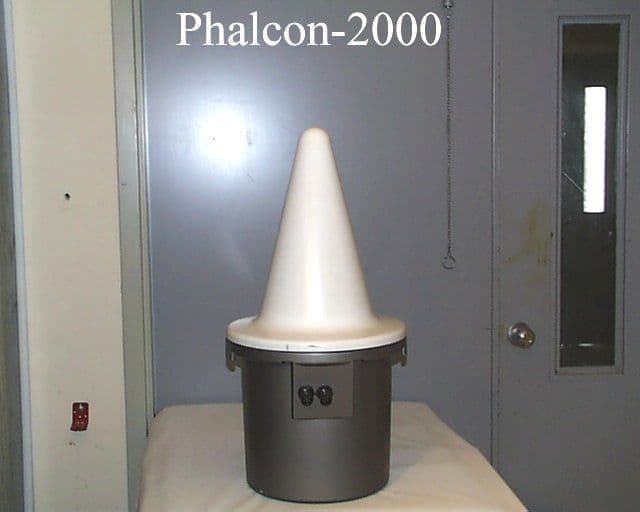
Click to zoom
Application Details
- Equipment Class
- MRD - Marine Radar
- Date of Grant
- Apr 24, 2000
- Application Purpose
- Original Equipment
- Date of Application
- Feb 03, 2000
- Equipment Note
- Radar Beacon (RACON)
- Frequency Range
- 2900.00000000 - 3100.00000000
- Company
- Automatic Power Inc
- Country
- United States
Documents & Files
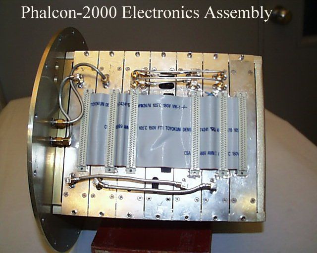
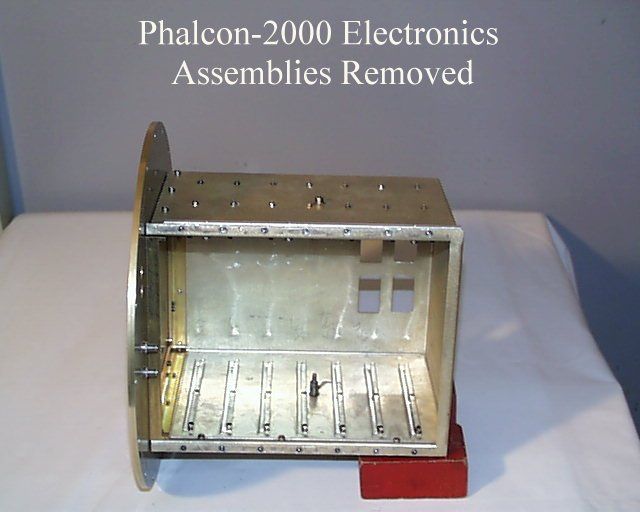
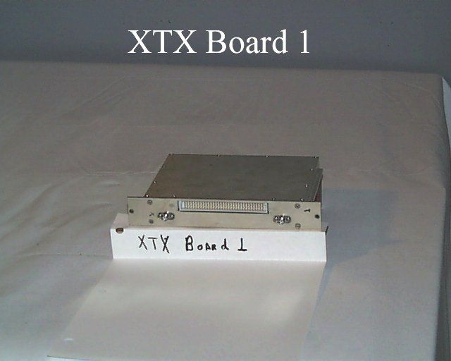
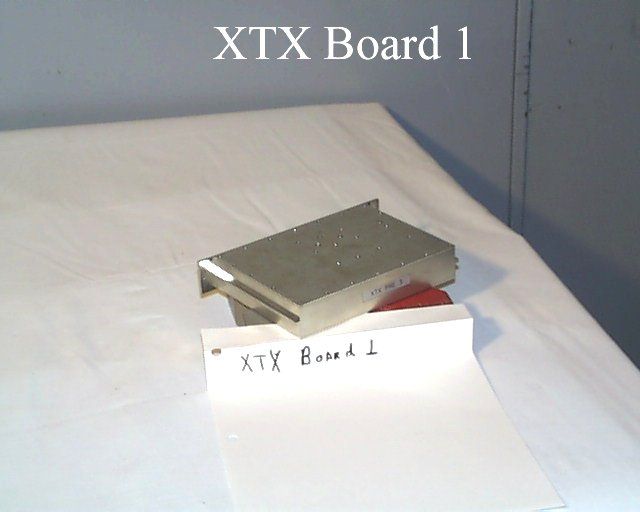
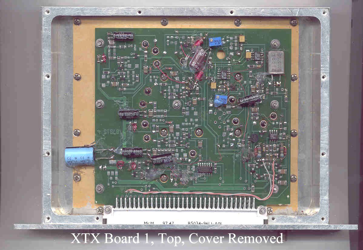
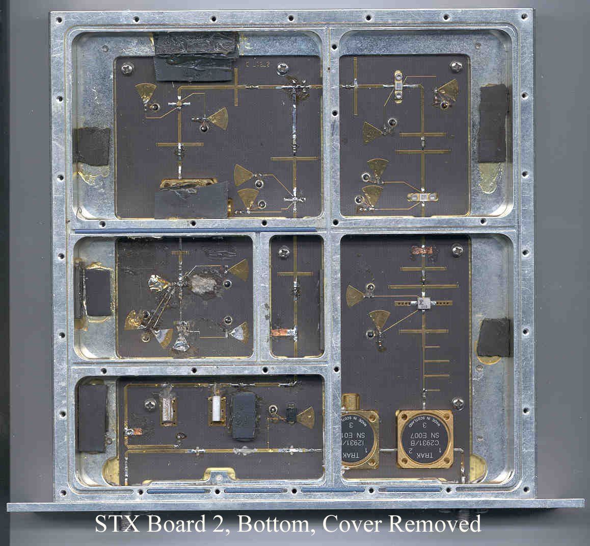
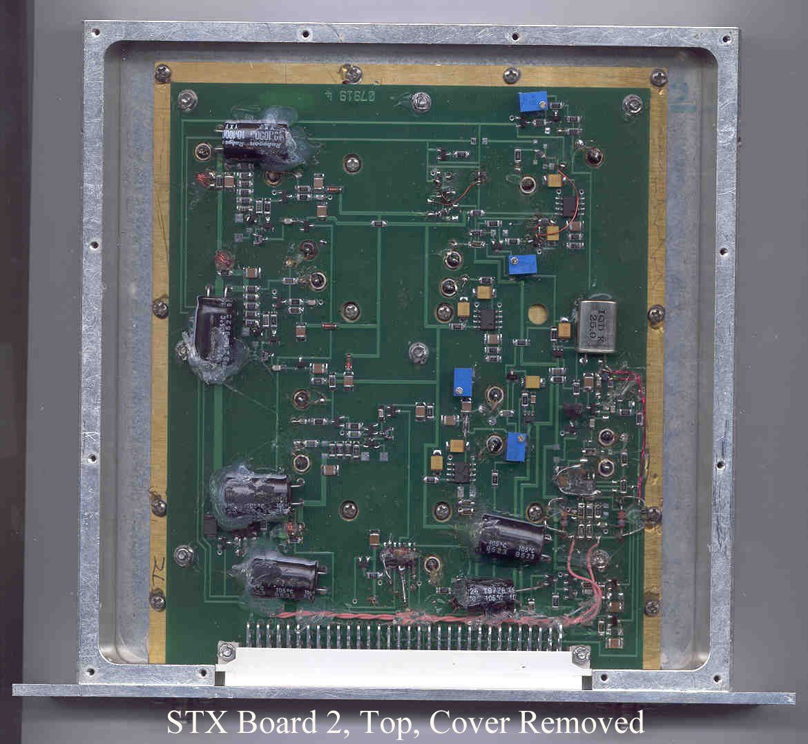
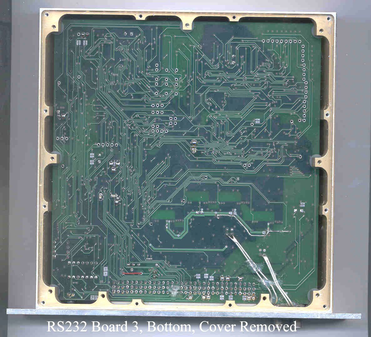
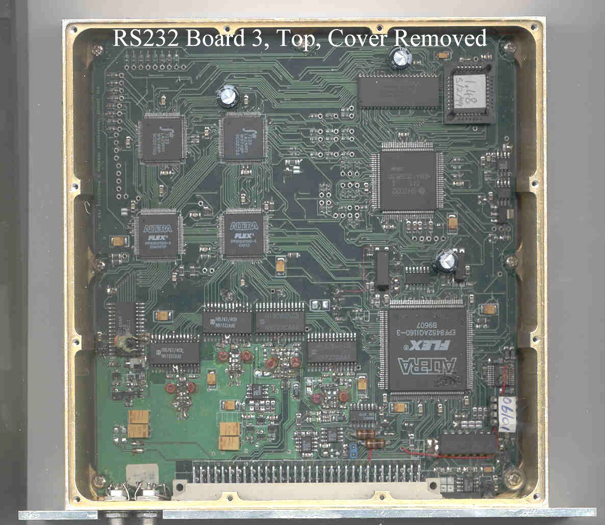
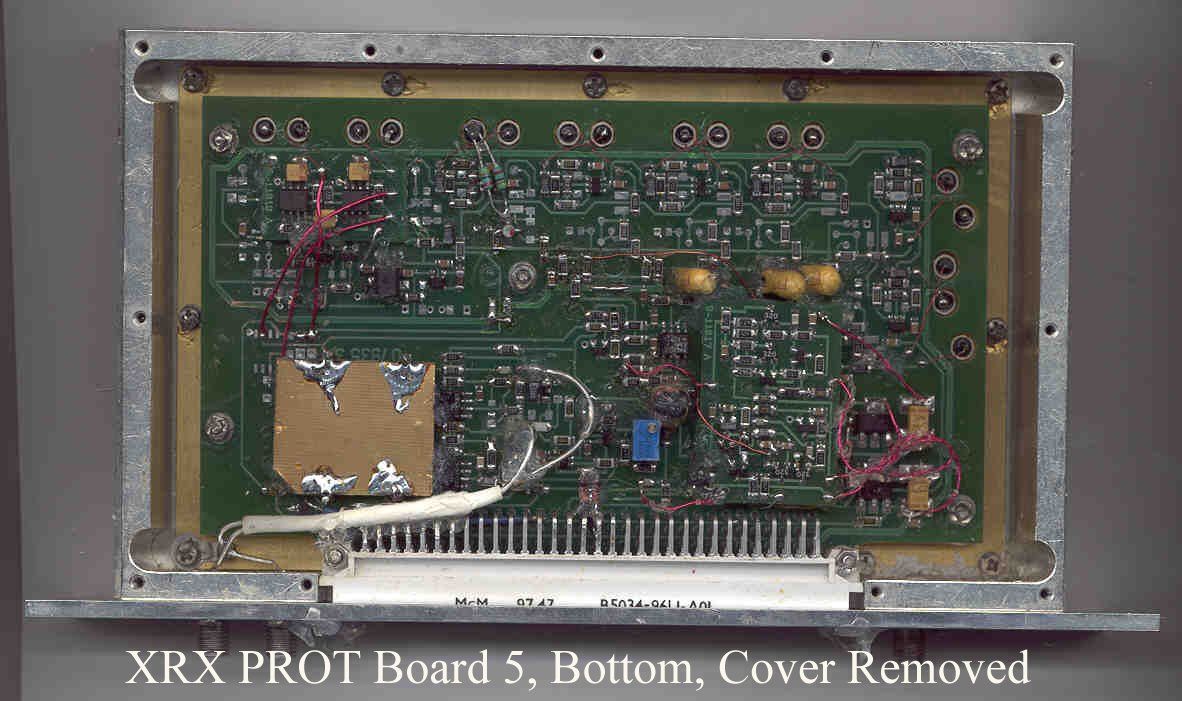
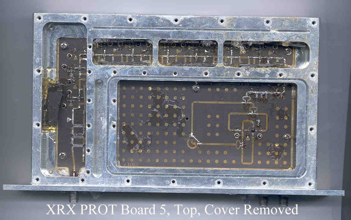
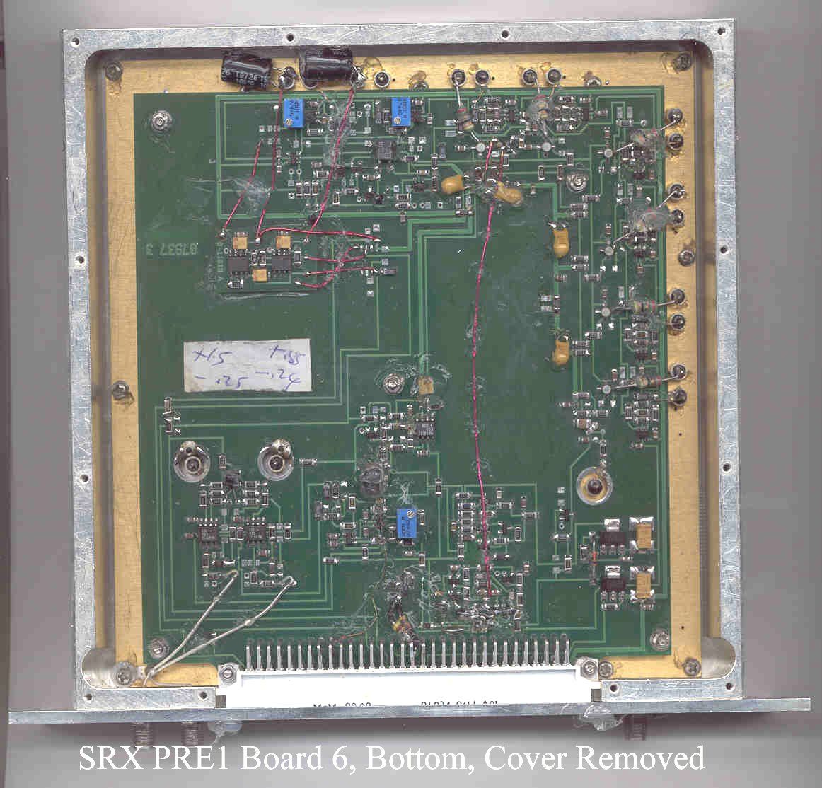
Document Text
Text extracted from the exhibit documents filed with the FCC. Open a document above to read the original.
Users Manual
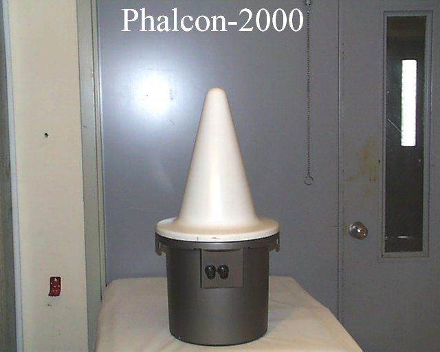
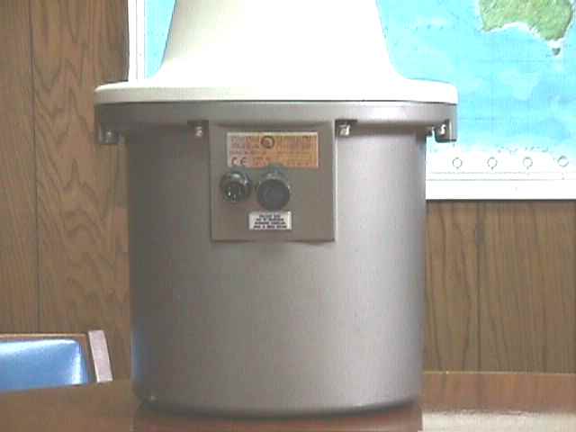
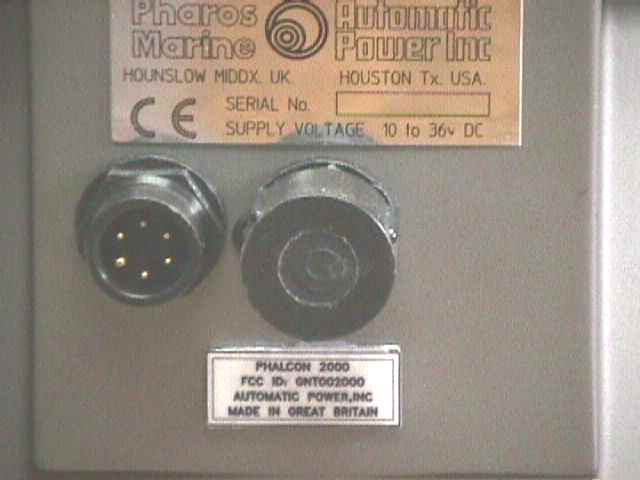
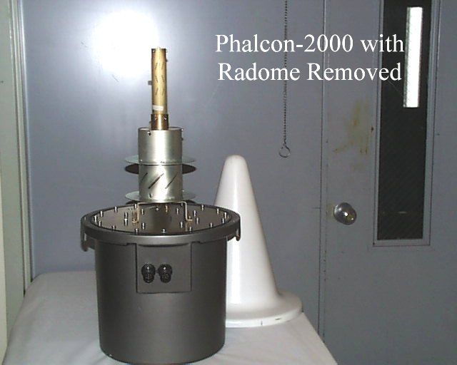
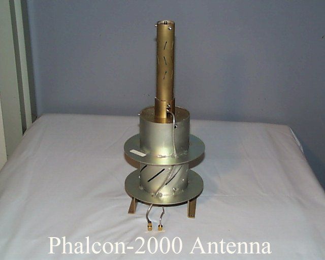
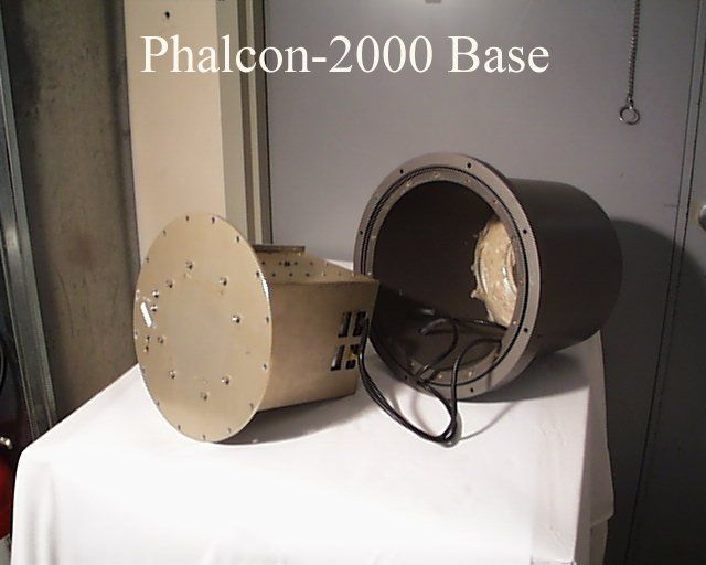
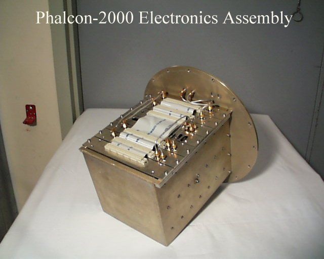
PHALCON 2000 Installation Guide Phalcon 2000 Installation Guide iiRef: HB-09300/01 Issue 1 © PHAROS MARINE 1999 The copyright in this document is vested in AB Pharos Marine Ltd. and the document is issued in confidence for the purpose only for which it is supplied. It must not be reproduced in whole or in part, or for tendering or manufacturing purposes, except under an agreement, or with the consent in writing of AB Pharos Marine Ltd., and then only on the condition that this notice is included in any such reproduction. Use this table to keep a record of the Phaclon 2000 details. Phalcon 2000 Serial Number: General Order (GO) Number: Morse Code Character: Sensitivity: Duty Cycle AB Pharos Marine Ltd. Steyning Way HOUNSLOW Middlesex TW4 6DL England Telephone:National: 0181 538 1100International: 44 181 538 1100 Telefax:National: 0181 847 0452International: 44 181 847 0452 Phalcon 2000 Installation Guide Ref: HB-09300/01 Issue 1 iii AMENDMENT RECORD Document Issue ECN NO.Sheets AffectedDate Incorporated Approval Phalcon 2000 Installation Guide ivRef: HB-09300/01 Issue 1 Contents Chapter 1Installation and Maintenance ...............................................................................................1 1.1 Job Set Up Information......................................................................................................1 1.2 Maintenance Requirements...............................................................................................1 1.3 Test Equipment .................................................................................................................1 1.4 Installation .........................................................................................................................2 1.4.1 Mounting ........................................................................................................4 1.4.2 Power Requirements ......................................................................................4 1.4.3 Junction Box...................................................................................................7 1.5 Commissioning..................................................................................................................9 Phalcon 2000 Installation Guide Ref: HB-09300/01 Issue 1 v SAFETY The safe installation, operation and maintenance of the equipment described in this document requires a high standard of training in safety and first aid skills. AB Pharos Marine Ltd. draw the attention of the user to the following particular skills and training that may be needed: Electrical SafetyBattery SafetyEmergency First Aid Electric ShockTreatment for ShockBurns Chemical BurnsRecovery PositionResuscitation Non-ionising Radiation Hazard It is recommended that personnel are at least 1 metre away from the Phalcon 2000 during its operation. DISCLAIMER 1. It is necessary to point out that the Company, or any of its associates, cannot accept responsibility for any form of personal injury, however caused, to anyone other than its employees; therefore every care should be taken to observe all the normal rules of safety. 2. The information contained within this document is correct and complete to our best knowledge and belief. The company cannot accept responsibility for the consequences of any errors or omissions howsoever caused. 3. In the event of any error being found the company would welcome corrections in the form of e-mail, facsimile or letter. 4. It is the policy of the company to continuously review and, where possible, improve its products. In the light of this policy, the information in this document may be out of date. Customers should always check the current specification before placement of order. Phalcon 2000 Installation Guide viRef: HB-09300/01 Issue 1 Summary A RAdar beaCON (RACON) – Phalcon 2000 – is a radar transponder that is triggered by signals transmitted by a marine radar, in either X or S frequency bands (3 cm or 10 cm wavelengths). It responds to this interrogation by transmitting a coded signal that is shown as a definable ‘paint’ on the interrogating radar display. The length of this code is scaled to the length of the received pulse, so the paint length on the radar screen remains similar for different range scales. The Phalcon 2000 (Figure 1) can be mounted on lighthouses, buoys, bridges, offshore platforms, breakwaters and other structures that need to be identified as an aid to navigation. This handbook covers Installation and Commissioning of the Phalcon 2000. Operation and Maintenance are covered in a companion manual - Phalcon 2000 Handbook. Phalcon 2000 Installation Guide Ref: HB-09300/01 Issue 1 vii Figure 1 Mechanical mounting details 356mm 3 MOUNTING HOLES M12 x 18.0 DEEP EQUALLY SPACED ON PCD 200.0 705mm Phalcon 2000 Installation Guide Ref: HB-09300/01 Issue 1 1 Chapter 1 Installation and Maintenance 1.1 Job Set Up Information Table 1 Tools and Equipment Part No / TypeDescriptionRemarks N/ATorque Wrench50-60 Nm (37-44 lbf) Fluke 75MultimeterCurrent consumption test N/ALaptop PC or palmtopRS232 plus terminal emulator Table 2 Consumable Materials Material No.DescriptionRemarks SealantSeal connectors GreaseBolt lubrication WARNING: BE CAREFUL WHEN YOU USE THE CONSUMABLE MATERIALS. OBEY THE MANUFACTURE'S HEALTH AND SAFETY INSTRUCTIONS. 1.2 Maintenance Requirements Following proper installation and commissioning, little maintenance should be necessary. To ensure trouble-free performance, it is recommended that Phalcon 2000 be inspected and cleaned, as detailed in the Phalcon 2000 Handbook (Ref: HB-09300/01 Issue 1). 1.3 Test Equipment For all diagnostics and most repair work on the Phalcon 2000, you will need a multimeter and a serial terminal, e.g. laptop computer that has an RS 232 interface connection and terminal emulation program. Phalcon 2000 Installation Guide 2Ref: HB-09300/01 Issue 1 1.4 Installation WARNING: BE CAREFUL WHEN YOU REMOVE OR INSTALL THE PHALCON 2000. THE PHALCON …
Text truncated - open the document above for the full version.
Test Report
FCC ID: GNT002000 P:\10-02192\202-fcr.doc 1 of 69 FCC MEASUREMENT AND TECHNICAL REPORT ON THE AUTOMATIC POWER INCORPORATED PHALCON–2000 RADAR BEACON Southwest Research Institute 6220 Culebra Road San Antonio, Texas 78228-0510 Project 10-02192-202 Report Number EMCR 99/129 Prepared for: Automatic Power, Inc. 213 Hutcheson Street Houston, TX 77003 Prepared by: David A. Carmony November 1999 The results of this test report apply only to the specific samples tested. If the manufacturer extends the test results to apply to other samples of the same model, or from the same lot or batch, the manufacturer should ensure the additional samples are manufactured using identical electrical and mechanical components. This test report shall not be reproduced, except in full, without the written approval of the Electromagnetic Compatibility Research Section, Southwest Research Institute. Reviewed by:Approved: Ismael Martinez, Jr.James J. Polonis Sr. Engineering TechnologistManager Electromagnetic Compatibility Research SectionElectromagnetic Compatibility Research Section FCC ID: GNT002000 P:\10-02192\202-fcr.doc 2 of 69 Communications Engineering DepartmentCommunications Engineering Department FCC ID: GNT002000 P:\10-02192\202-fcr.doc 3 of 69 TABLE OF CONTENTS Page List of Tables ................................................................................................................................................ 4 1.0General Information.......................................................................................................................... 5 1.1 Product Description ......................................................................................................................... 5 1.2Related Grants ................................................................................................................................. 5 1.3Tested System Details...................................................................................................................... 5 1.4Test Methodology............................................................................................................................ 6 1.5Test Facility ..................................................................................................................................... 6 2.0Applicable Documents ..................................................................................................................... 7 2.1FCC ID Label .................................................................................................................................. 7 2.2Location of Label on EUT ............................................................................................................... 7 3.0System Test Configuration .............................................................................................................. 8 3.1Justification ..................................................................................................................................... 8 3.2EUT Exercise ................................................................................................................................ 8 3.3Special Accessories ......................................................................................................................... 8 3.4Equipment Modification.................................................................................................................. 8 3.5 Configuration of Tested System ...................................................................................................... 8 4.0EMC Tests........................................................................................................................................ 9 4.1Power Output .................................................................................................................................. 9 4.1.1Test Procedures ............................................................................................................................... 9 4.1.2Test Results ..................................................................................................................................... 9 4.2Occupied Bandwidth ...................................................................................................................... 9 4.2.1Test Procedures ............................................................................................................................... 9 4.2.2Test Results ................................................................................................................................... 10 4.3Spurious Emissions at Antenna Terminals .................................................................................... 10 4.3.1Test Procedures ............................................................................................................................. 10 4.3.2Test Results ................................................................................................................................... 10 4.4Field Strength of Spurious Radiation............................................................................................. 11 4.4.1Test Procedures .............................................................................................................................. 11 4.4.2Test Results ................................................................................................................................... 11 4.5Frequency Stability......................................................................................................................... 11 4.5.1Test Procedures ............................................................................................................................. 11 4.5.2Test Results ...................................................................................................................................…
Text truncated - open the document above for the full version.
Test Report
The FCC requested additional information in reference to the submission for certification of the Automatic Power Phalcon-2000 Radar Beacon. The data below and the attached data plots revises paragraphs 4.1.2, 4.3.1, and Appendix D of the SwRI test report entitled “FCC Measurement and Technical Report on the Automatic Power Incorporated Phalcon-2000 Radar Beacon,” dated November 1999 (report no. 99/129). Question 1 from the FCC: Since this unit has a built-in antenna, the power output listings should be in terms of ERP. Please supply these values. The effective radiated power (ERP) from the Phalcon-2000, with reference to a half-wave dipole, is shown in the following table. The calculated average factor was applied to each level of computed ERP. Band Frequency (MHz) Peak Power at Antenna Terminals Peak Power at Antenna Terminals with average factor applied ERP with Reference to a Half-wave Dipole Antenna dBmPowerdBmPowerdBmPower S2905+27501 mW+20.6115 mW+22.74189 mW 3000+28631 mW+21.6145 mW+23.74238mW 3095+27.1513 mW+20.7117 mW+22.84192 mW X9305+28.3676 mW+21.9155 mW+24.04254 mW 9400+29.7933 mW+23.3214 mW+25.44351 mW 9495+28.5708 mW+22.1162 mW+24.24266 mW Question 2 from the FCC: The attenuation specification for radiated spurious emissions should be computed on the basis of the (average) ERP. Please do this and report the results on that basis. The harmonics and spurious emissions were required to be 43 plus 10 log (average ERP in watts) dB below the fundamental emission: BandLimit S 43 + 10 log (.238) dB =36.8 dB (below fundamental) X 43 + 10 log (.351) dB =38.5 dB (below fundamental) The data plots showing the radiated spurious emissions have been revised to show the corrected attenuation levels based on average ERP. These plots are attached to this letter. The worst case emission level was detected from the S-band, horizontal polarization, at 14.478 GHz, and was 5 dB under the limit. Question 3 from the FCC: We did not receive a letter requesting Confidentiality as required by Section 0.459 of the Commission's R&R Please supply this letter with details as required. The following letter was originally sent by Mr. Bill Peterman of Automatic Power with the signed Form 159 and the payment for the FCC compliance submittal. The request for confidentially is included in the letter. Federal Communications Commission Equipment Approval Services P.O. Box 358315 Pittsburgh, PA 15251-5315 Dear Sirs: Enclosed is a completed and signed Form 159, along with payment for FCC compliance submittal referenced by FCC ID: GNT002000, confirmation #EA96701. It is requested that confidentiality be maintained for all schematics, block diagrams, and operational descriptions. Thank you, William M. Peterman Sr. Electronic Engineer Automatic Power, Inc.
Contact Information
Applicant
Guy T Priestley
Technical Contact
Automatic Power, Inc.Bill Peterman
[email protected]713-228-5208
213 Hutcheson Street · Houston, Texas · United States
Non-Technical Contact
Automatic Power, Inc.Bill Peterman
[email protected]713-228-5208
Test Firm
Southwest Research InstituteDavid Carmony
210-684-5111
Technical Specifications
| # | Rule Parts | Frequency Range | Power Output | Emission |
|---|---|---|---|---|
| 2 | 80.213(h) | 2.90 GHz - 3.10 GHz | 240.00 mW | 21M4L1N |
Other Applications from Automatic Power Inc
GNTPMR3
Apr 11, 1993MRD - Marine Radar
Equipment Class
MRD - Marine RadarGNT8NBUKT10101
Mar 05, 1989TNB - Licensed Non-Broadcast Station Transmitter
Equipment Class
TNB - Licensed Non-Broadcast Station TransmitterGNT8NBUKT10103
Mar 05, 1989TNB - Licensed Non-Broadcast Station Transmitter
Equipment Class
TNB - Licensed Non-Broadcast Station TransmitterGNT8NBUKT10104
Mar 05, 1989TNB - Licensed Non-Broadcast Station Transmitter
Equipment Class
TNB - Licensed Non-Broadcast Station TransmitterGNT8NBUKT10102
Nov 08, 1988TNB - Licensed Non-Broadcast Station Transmitter
Equipment Class
TNB - Licensed Non-Broadcast Station Transmitter