GOLNPX136DVHF Transceiver
Wulfsberg Electronics Division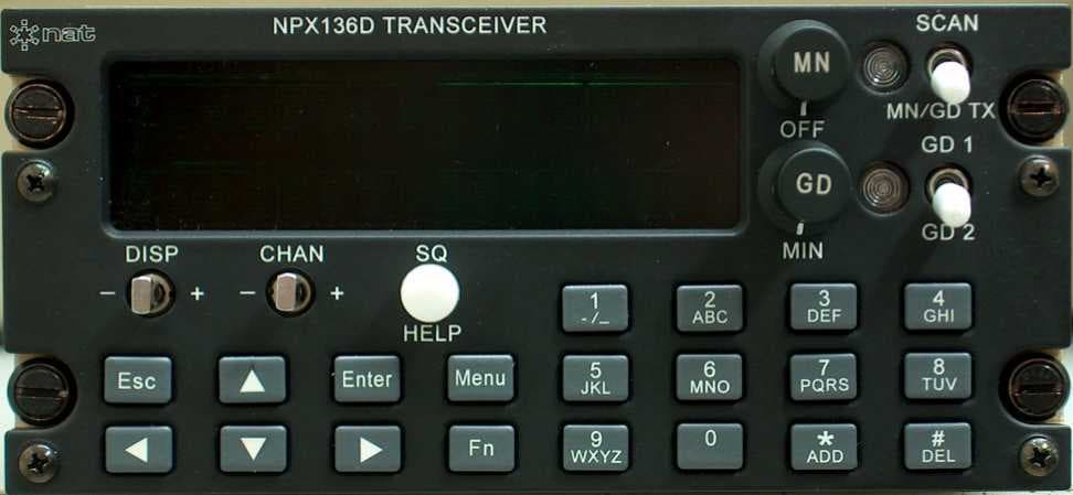
Click to zoom
Application Details
- Equipment Class
- TNB - Licensed Non-Broadcast Station Transmitter
- Date of Grant
- Apr 26, 2004
- Application Purpose
- Original Equipment
- Date of Application
- Apr 26, 2004
- Equipment Note
- VHF Transceiver
- Frequency Range
- 136.00000000 - 174.00000000
- Country
- United States
Documents & Files
Document Text
Text extracted from the exhibit documents filed with the FCC. Open a document above to read the original.
Users Manual
Page 1 NPX136D-070 VHF P25 Panel Mount Transceiver OPERATOR’S MANUAL REV 0.01 April 5, 2004 Northern Airborne Technology Ltd. #14-1925 Kirschner Road Kelowna, BC, Canada. V1Y 4N7 Telephone (250) 763-2232 Facsimile (250) 762-3374 Copyright 2004 by Northern Airborne Technology Ltd. Page 2 Table of Contents Section Title Page 1.1 Introduction 3 1.2 Purpose of Equipment 3 1.3 Features 3 1.4 Operation 4 1.4.1 General 4 1.4.2 Power On 4 1.4.3 Controls 5 1.4.4 Normal Operating Mode 8 1.4.5 Menu Mode 10 1.4.6 Direct Function Operations 19 1.4.7 Scanning 19 1.5 Specifications 20 1.5.1 Radio Specifications 20 1.5.2 Main Receiver 21 1.5.3 Guard Receiver 21 1.5.4 Transmitter 21 1.5.5 Physical Specifications 22 1.5.6 Environmental Specifications 23 1.6 Unit Nomenclature 23 1.6.1 Options 23 Page 3 1.1 Introduction This manual contains description and operation information on the NPX136D-070 Panel Mount P25 VHF Transceiver, serial number 1001 and subsequent. The NPX136D incorporates NAT’s proven user-friendly operating system with on-line help, making it easy to program and use. The small size makes this radio ideal for airframes where size and weight are a factor. 1.2 Purpose of Equipment The NPX136D panel mount P25 VHF transceiver is a stand-alone radio designed for the single mission user. It provides all the features needed to satisfy communications within the VHF high band. 1.3 Features The NPX136D covers a frequency range of 136.0000 to 173.9975 MHz in 2.5/6.25 kHz increments. Each of the 256 available channels can operate in one of three modes: wide band analog, narrow band analog or digital P25 Phase I. A SCAN function allows scanning of selected channels. Transmit power of either 1 watt or 10 watts is selectable from the front panel. Simplex and semi-duplex operations are available. A guard receiver is standard with the -070 model. Conveniently located beside the display are separate main volume, guard volume and transmit select switches. Easily identified along the bottom of the front panel are squelch test, channel up/down and display controls. The aircraft dimmer buss provides control for the panel lighting. Page 4 1.4 Operation 1.4.1 General In addition to the general functions that are available on other FM radios, the NPX has several features that extend its capability and make it easier to use. These features include alphanumeric channel labeling, built-in operator help, scanning, optional guard receiver, and numerous others. For ease of use and operability, NAT uses a similar control layout and operating system in the NPX138 series of radios as it does in its popular Tac/Com family of radio control heads. In addition to this manual, there is a help function built into the radio comprehensive enough to address most operational questions. 1.4.2 Power On 1.4.2.1 Power-up Screen Turn the NPX on by rotating the main (MN) volume control clockwise, away from the ‘Off’ detent position. The software revision number will briefly display, and, if enabled, will be followed by a screen presenting an option for use of the on-line Help system. To display a tutorial on the operation of the radio press the SQ/HELP button. To advance through the tutorial press Enter after reading each screen. To exit the tutorial press the ESC button. NPX136D S/W Ver: X.XX Page 5 1.4.2.2 Initial Operating Display If you decline ‘Help’ (by pressing the Esc button), the radio will display a summary of the installed functions and current settings (this feature can be disabled for faster start-up). The radio is then ready for normal operation, referred to as normal operating mode in the remainder of this manual. 1.4.3 Controls 1.4.3.1 Main Receive Volume and Power On / Off Control To turn on the radio rotate the MN knob clockwise past the OFF detent. To turn off the radio rotate the MN knob counterclockwise past the OFF detent. To increase the volume of the main receiver, turn this knob clockwise; to decrease the volume turn this knob counterclockwise. 1.4.3.2 Guard Receive Volume To increase the volume of the guard receiver, turn this knob clockwise; to decrease the volume turn this knob counterclockwise. The guard receive audio cannot be turned off, only set to a minimum level. Main On/Off/Volume Main RX/TX Annunciator 001=ABCDEFGHI W S C R:173.975 067 Radio Status: Tx Mode=Duplex Scan Guard Transmit Guard Volume Guard RX/TX Annunciator Guard Channel Display Switch Channel Switch Squelch/Help Switch Keypad Push Buttons Page 6 1.4.3.3 Main RX/TX Status Annunciator The main RX/TX annunciator displays the RX (Receive) and the TX (Transmit) status of the main transceiver. When transmitting the LED will light green. When receiving any RF signal, the LED will light amber. When idle (not receiving or transmitting), the LED will be dark. The colour coding used for these functions corresponds to standard aircraft FM radio conventions. Note that this is the reverse of standard vehicular conventions used with land mobile equipment. The receive annunciator (amber) informs the operator that the channel is active with radio traffic of some kind. A radio that is receiving may still not produce any audio if the analog tones or digital squelch mode present on the receive signal do not match those set in the radio. 1.4.3.4 Guard RX/TX Status Annunciator The guard RX/TX annunciator displays the RX (Receive) and the TX (Transmit) status of the guard channel. When the main transceiver is transmitting on the guard channel (SCAN / GD TX switch in GD TX position) the LED will light green. When the guard receiver is receiving any RF signal, the LED will light amber. When idle (not receiving or transmitting), the LED will be dark. 1.4.3.5 Change channels on the main receiver There are two different ways to select a channel on the main transceiver. Step or scroll through the channels using the CHAN switch. To sequentially change channels press the CHAN switch right ‘+’ to increment by one channel or left ‘-’ to decrement by one channel. Holding the…
Text truncated - open the document above for the full version.
Users Manual
SMtbd Rev. 0.01 NPX136D Panel Mount Radio Manual Apr 23, 2004 Page 2-1 ENG-FORM: 805-0104.DOT PROPRIETARY AND CONFIDENTIAL TO NORTHERN AIRBORNE TECHNOLOGY LTD. Section 2.0 Installation 2.1 Introduction Information in this section consists of: unpacking and inspection procedures, installation procedures, post-installation checks, and installation drawings. 2.2 Unpacking and Inspection Unpack the equipment carefully, and locate the warranty card. Inspect the unit visually for damage due to shipping and report all such claims immediately to the carrier involved. Note that each unit should have the following: - NPX136D Radio - Warranty Card - Operator’s Manual - Release certification Verify that all items are present before proceeding, and report any shortage immediately to your supplier. Complete the warranty card information, and send it to NAT when the installation is complete. If you fail to complete the warranty card, the warranty will be activated on date of shipment from NAT. 2.3 Installation Procedures 2.3.1 Note on Cable Routing Do not bundle any lines from this unit with transmitter coax lines. Do not bundle any logic, audio, or DC power lines from this unit with 400 Hz synchro wiring or AC power lines. Do not position this unit next to any device with a strong alternating magnetic field such as an inverter or significant interference to operation will result. In all installations, use shielded cable exactly as shown and ground as indicated. Significant problems may result if these guidelines are not followed. 2.3.2 Notes on Cable Wiring and Shielding All audio installations can be severely degraded by incorrect wiring and shielding, and may result in much higher cross-talk, hum, and ground-loop interference. This should be considered when audio wiring to and from the radio installation is performed. PRELIMINARY NPX136D Panel Mount Radio Manual SMtbd Rev. 0.01 Page 2-2 April 26, 2004 ENG-FORM: 805-0104.DOT PROPRIETARY AND CONFIDENTIAL TO NORTHERN AIRBORNE TECHNOLOGY LTD. 2.3.3 Notes on Grounding The case of the NPX136D must be electrically grounded for maximum resistance to low frequency interference. A pin on the connector (Chassis ground) is provided and must be connected by a short wire to a clean ground, not jumpered to the power ground wire connection. Refer to the aircraft structural repair manual and maintenance manual for instructions and information pertinent to this installation. 2.3.4 Cable and Wiring All wire should be in accordance with MIL-W-22759 unless otherwise specified. All cable should be in accordance with MIL-C-27500 unless otherwise specified. Use solder sleeves (for shielded terminations) to make the most compact and easy to terminate interconnect. Follow the wiring diagrams in Section 2.5 as required. Allow 3 inches from the end of the wire to the shield termination to allow the hood to be easily installed. Note that the hood is installed after the wiring is complete. Installation cabling must allow the NPX136D to be easily withdrawn for disconnection and field service adjustments. Ensure an adequate service loop in the routing of the cables. It can be a serious issue if the unit is installed with the cables so short that the unit cannot be removed without disassembly of the surrounding structures. At least 30 cm (1 foot) of free cable is recommended. All wiring should be 22 AWG minimum, except power and ground connections, which must be 20 AWG or larger, as indicated on the installation drawings. Ensure that the ground connection is clean and well secured. To prevent inadvertent system failure, power to this system must be supplied from a separate breaker or fuse and not connected to any other device. A 5 A fuse or breaker is recommended (28 Vdc). Coaxial cable should be in accordance with MIL-C-17 unless otherwise specified. Do not use coax with PVC insulation. Teflon dielectric cable is encouraged at or above VHF frequencies or where cable runs exceed 8 feet. Note that at VHF frequencies, cable losses due to long cable runs and tight bends may cut the ERP (Equivalent Radiated Power) to less than 50% of spec. To prevent RF interference between similar systems, it is recommended that VHF FM coax runs be widely separated, or be made using triaxial cable, with the outer shield bonded to the airframe at one end only (transceiver end). In communication intensive applications, poor cable routing and shielding may drastically compromise over-all system performance. Symptoms may be spurious squelch opening, RFI (Radio-Frequency Interference), and garbled reception. SMtbd Rev. 0.01 NPX136D Panel Mount Radio Manual Apr 23, 2004 Page 2-3 ENG-FORM: 805-0104.DOT PROPRIETARY AND CONFIDENTIAL TO NORTHERN AIRBORNE TECHNOLOGY LTD. RF cables must be neatly terminated (solder or crimp), and tested for shorts prior to system check-out (not while connected to the radio or antenna). Keep cable bends to a minimum at the antenna. Avoid sharp bends in the coax cables (minimum 3" radius) to prevent severe reflections. If sharp bends are required, use 90° elbow adapters. Fabrication & installation of wiring harness should be in accordance with AC 43.13-1A chapter 11, sections 3 and 7. Grounding and bonding should be in accordance with AC 43.13-1A chapter 11, section 3. 2.3.5 Antennas Warning: To limit exposure from radio frequency fields that exceed exposure limits for people occupying the aircraft, install the antenna such that it is mounted; on a ground plane that is between the antenna and the occupants of the aircraft, or farther than 32 inches (80cm) from the occupants of the aircraft. Correct antenna placement and mounting is critical in order to achieve the best possible performance. In general, keep all antennas as widely separated as possible and clear of any large airframe obstructions. Installation of the antenna should be in accordance with AC 43.13-1A chapter 2, section 3, chapters 5 & 6, and AC 43.13-2A chapter 3. If possible, the antenna should be located a minimum o…
Text truncated - open the document above for the full version.
Cover Letter(s)
1. Please provide additional external views showing front and rear of the device. Front and rear pictures attached. 2. Has the device been tested for RF power output with 1W setting to see deviation from manufacturer ratings? Please clarify. Yes, here are the 1 watt power levels At 136.000 MHz NB 30.30 dBm WB 30.31 dBm Digital 30.31 dBm At 155.000 MHz NB 30.31 dBm WB 30.14 dBm Digital 30.14 dBm At 173.9975 MHz NB 30.03 dBm WB 30.04 dBm Digital 30.04 dBm 3. Please supply the tune-up procedure Supplied 4. Does the device have the capability of transmitting on multiple channels simultaneously? Please clarify. I confim that the NPX136D-070 radio, when in transmit mode, can only transmit on a single channel at a given time. The NPX136D-070 radio has two transceiver modules. These modules are refered to as the main module and the guard module. The main transceiver module can only transmit on one channel at a given time. The guard transceiver module can not transmit. It is configured only for receive. There is a function on the radio that is called the guard transmit mode, but in this mode the main transceiver module is programmed with the required frequency for the guard channel and the transmit carrier is generated from the main transceiver module.
ID Label/Location Info
MODEL NO.RF OUTPUT PWRSERIAL NO. DATEWEIGHT MODIFICATION STATUS LIGHTING POWER DESCRIPTION NPX136D10 W max 201915 17 1816 14 13 12 lbs. VDC 10 11 98765 28 VDC 3 421 P25 VHF TRANSCEIVER MADE IN KELOWNA, B.C. CANADA .DTLEaNROBRIYOECHNOLGtnNREHTRO THIS DEVICE MADE UNDER LICENSE UNDER ONE OR MORE OF THE FOLLOWING U.S. PATENTS: 4,590,473; 4,636,791; 4,833,701; 4,972,460; 5,146,497; 5,148,482; 5,164,986; 5,185,795; 5,185,796; 5,271,017; 5,377,299
Test Report
Master: FCCPart22-90.doc Date: February 13, 2002 Test Report: 4W07941 Applicant: Northern Airborne Technology Ltd. 1925 Kirschner Road Kelowna, BC, V1Y 4N7 Equipment Under Test: NPX136D-070, (EUT) VHF Radio FCC ID: GOLNPX136D In Accordance With: FCC Part 22 FCC Part 90 Tested By: Nemko Canada Inc. 303 River Road, R.R. 5 Ottawa, Ontario K1V 1H2 Authorized By: Glen Westwell, Wireless Technologist Date: 16 April 2004 Total Number of Pages: 31 Nemko Canada Inc. FCC PART 22 & FCC PART 90 PROJECT NO.:4W07941 EQUIPMENT: NPX136D-070, VHF Radio Page 2 of 31 Table of Contents Section 1. Summary of Test Results ...................................................................................3 Section 2. General Equipment Specification......................................................................5 Section 3. RF Power Output ................................................................................................7 Section 4. Audio Low-Pass Filter Response .......................................................................8 Section 5. Modulation Limiting.........................................................................................10 Section 6. Occupied Bandwidth ........................................................................................12 Section 7. Spurious Emissions at Antenna Terminals ....................................................16 Section 8. Field Strength of Spurious Emissions .............................................................19 Section 9. Frequency Stability............................................................................................22 Section 10. Transient Frequency Behaviour .......................................................................24 Section 11. Block Diagrams ..................................................................................................27 Section 12. Test Equipment List ..........................................................................................31 Nemko Canada Inc. FCC PART 22 & FCC PART 90 PROJECT NO.:4W07941 EQUIPMENT: NPX136D-070, VHF Radio Page 3 of 31 Section 1. Summary of Test Results General All measurements are traceable to national standards. These tests were conducted on a sample of the equipment for the purpose of demonstrating compliance with FCC Part 22 and FCC Part 90. THIS TEST REPORT RELATES ONLY TO THE ITEM(S) TESTED. THE FOLLOWING DEVIATIONS FROM, ADDITIONS TO, OR EXCLUSIONS FROM THE TEST SPECIFICATIONS HAVE BEEN MADE. See “ Summary of Test Data”. TESTED BY: ______________________________ DATE: 16 April 2004 Kevin Carr, EMC/EMI/Wireless Specialist Nemko Canada Inc. authorizes the above named company to reproduce this report provided it is reproduced in its entirety and for use by the company’s employees only. Any use which a third party makes of this report, or any reliance on or decisions to be made based on it, are the responsibility of such third parties. Nemko Canada Inc. accepts no responsibility for damages, if any, suffered by any third party as a result of decisions made or actions based on this report. This report applies only to the items tested. Nemko Canada Inc. FCC PART 22 & FCC PART 90 PROJECT NO.:4W07941 EQUIPMENT: NPX136D-070, VHF Radio Page 4 of 31 Summary Of Test Data Name Of Test Para. No. Result RF Power Output 2.1046 Complied Audio Frequency Response 2.1047 Complied Audio Low-Pass Filter Response 2.1047 Complied Modulation Limiting 2.1047 Complied Occupied Bandwidth 2.1049 Complied Spurious Emissions at Antenna Terminals 2.1051 Complied Field Strength of Spurious Emissions 2.1053 Complied Frequency Stability 2.1055 Complied Transient Frequency Behavior —— Complied Footnotes For N/A’s: Test Conditions: Indoor Temperature: 24°C Humidity: 17% Outdoor Temperature: 7°C Humidity: 78% . Nemko Canada Inc. FCC PART 22 & FCC PART 90 PROJECT NO.:4W07941 EQUIPMENT: NPX136D-070, VHF Radio Page 5 of 31 Section 2. General Equipment Specification Manufacturer: Northern Airborne Technology Ltd. Model No.: NPX136D-070 Serial No.: 1002 Date Received In Laboratory: 23 Mar. 2004 Nemko Identification No.: 1 Transmitter Power Input: 28 VDC Frequency Range: 136.0000 – 173.9975 MHz 99% Occupied Bandwidth: Analog Voice–WB 14.7kHz Analog Voice–NB 5.8kHz Digital Voice 7.0kHz Emission Designator: Analog Voice–WB 14kF3E Analog Voice–NB 05k8F3E Digital Voice 07k0F1E Crystal Frequencies: 5, 12.8, 20 MHz Power Output (Manufacturer's Rating): 40.0 dBm, 10.0 Watts Power Output Adjustment: 1W/10W factory presets Operator Selection of Operating Frequency: Front Panel Control – 1W/10W Nemko Canada Inc. FCC PART 22 & FCC PART 90 PROJECT NO.:4W07941 EQUIPMENT: NPX136D-070, VHF Radio Page 6 of 31 Receiver Power Input: 28 VDC Frequency Range: 136.0000 – 173.9975 MHz Tunable Bands: 1 Operator Selection of Operating Frequency: Front Panel Control Nemko Canada Inc. FCC PART 22 & FCC PART 90 PROJECT NO.:4W07941 EQUIPMENT: NPX136D-070, VHF Radio Page 7 of 31 Section 3. RF Power Output Para. No.: 2.1046 Test Performed By: Kevin Carr Date of Test: 23 Mar. 2004 Minimum Standard: ± 1 dB Test Results: Complied Measurement Data: Manufacturer's Rating: 40.0dBm Measured Power Output: 40.6dBm Nemko Canada Inc. FCC PART 22 & FCC PART 90 PROJECT NO.:4W07941 EQUIPMENT: NPX136D-070, VHF Radio Page 8 of 31 Section 4. Audio Low-Pass Filter Response Para. No.: 2.1047 Test Performed By: Kevin Carr Date of Test: 23 Mar. 2004 Minimum Standard: Not applicable. Test Results: Complied The equipment has provision for audio low pass filter. Measurement Data: See attached graph. Nemko Canada Inc. FCC PART 22 & FCC PART 90 PROJECT NO.:4W07941 EQUIPMENT: NPX136D-070, VHF Radio Page 9 of 31 Audio Response N.B. Audio Frequency Response -80 -60 -40 -20 0 20 100100010000 Frequency (Hz) Response (dB) W.B. Audio Frequency Response -80 -60 -40 -20 0 20 100100010000 Frequency (Hz) Response (dB) Nemko Canada Inc. FCC PART 22 & FCC PART 90 PROJECT NO.:4W07941 EQUIPMENT: NPX136D-070, VHF Radio Page 10 of 31 Secti…
Text truncated - open the document above for the full version.
Test Setup Photos
Nemko Canada Inc. FCC PART 22 & FCC PART 90 PROJECT NO.:4W07941 EQUIPMENT: NPX136D-070, VHF Radio Page 21 of 31 Set up Photos:
Contact Information
Applicant
James F Buehring
Test Firm
Nemko Canada Inc.Stuart Beck
Technical Specifications
| # | Rule Parts | Frequency Range | Power Output | Emission | Tolerance |
|---|---|---|---|---|---|
| 4 | 22,9 | 136 MHz - 174 MHz | 10 W | 7K00F1E | 2.5 ppm |
Other Applications from Wulfsberg Electronics Division

GOL-NTX403
May 29, 2003NTX403 UHF FM Transceiver
Equipment Class
TNB - Licensed Non-Broadcast Station Transmitter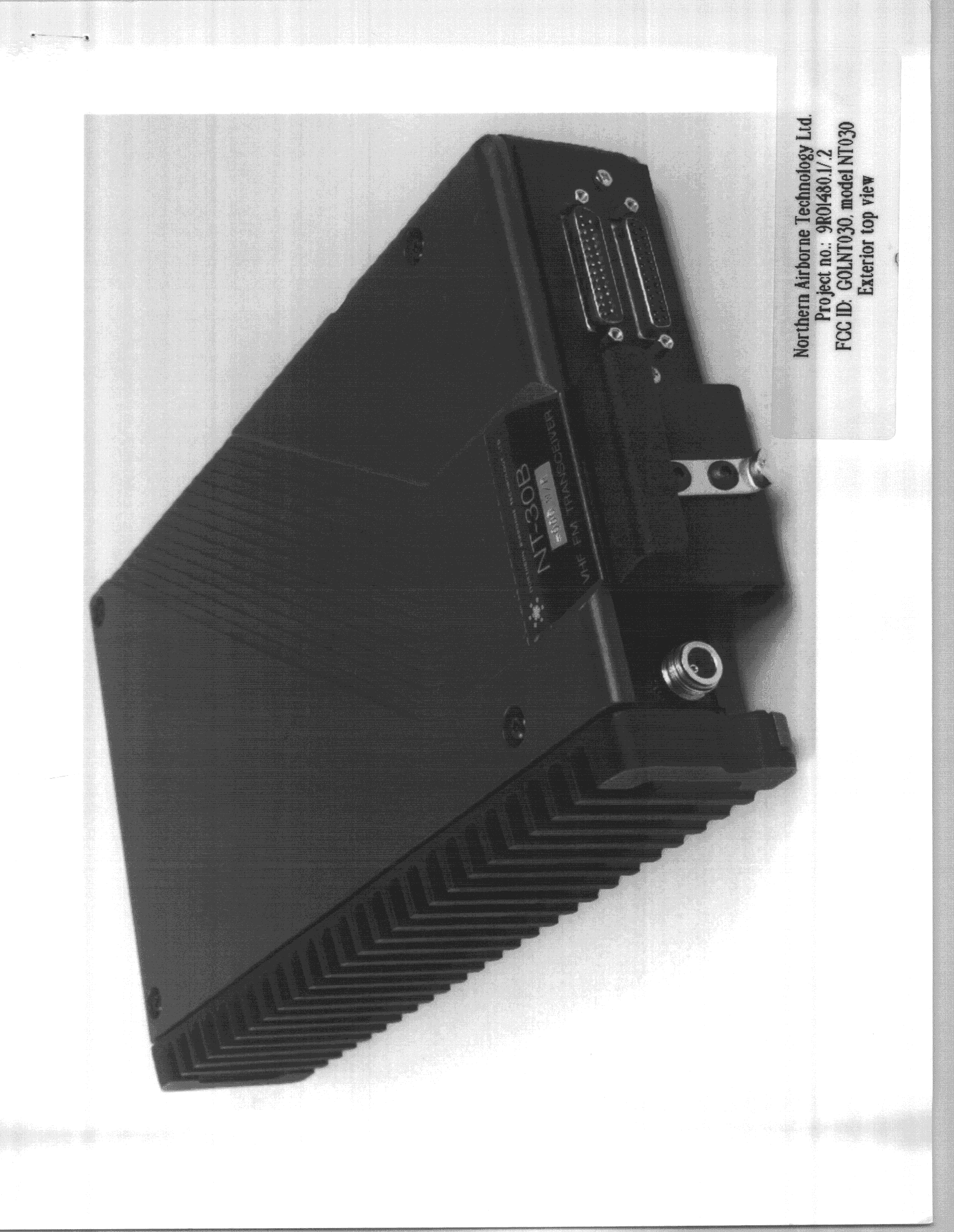
GOLNT030
Sep 16, 1999TNB - Licensed Non-Broadcast Station Transmitter
Equipment Class
TNB - Licensed Non-Broadcast Station TransmitterGOL3YH-NPX138
Mar 10, 1997Single Channel Mode
Equipment Class
TNB - Licensed Non-Broadcast Station TransmitterGOL3YH-NTX138
Feb 13, 1997Single Channel Mode
Equipment Class
TNB - Licensed Non-Broadcast Station TransmitterGOL3YHNT450
Oct 21, 1987TNB - Licensed Non-Broadcast Station Transmitter
Equipment Class
TNB - Licensed Non-Broadcast Station Transmitter