GTOLBS18BT HEADPHONE
Shenzhen Linpa Technology Co.,Ltd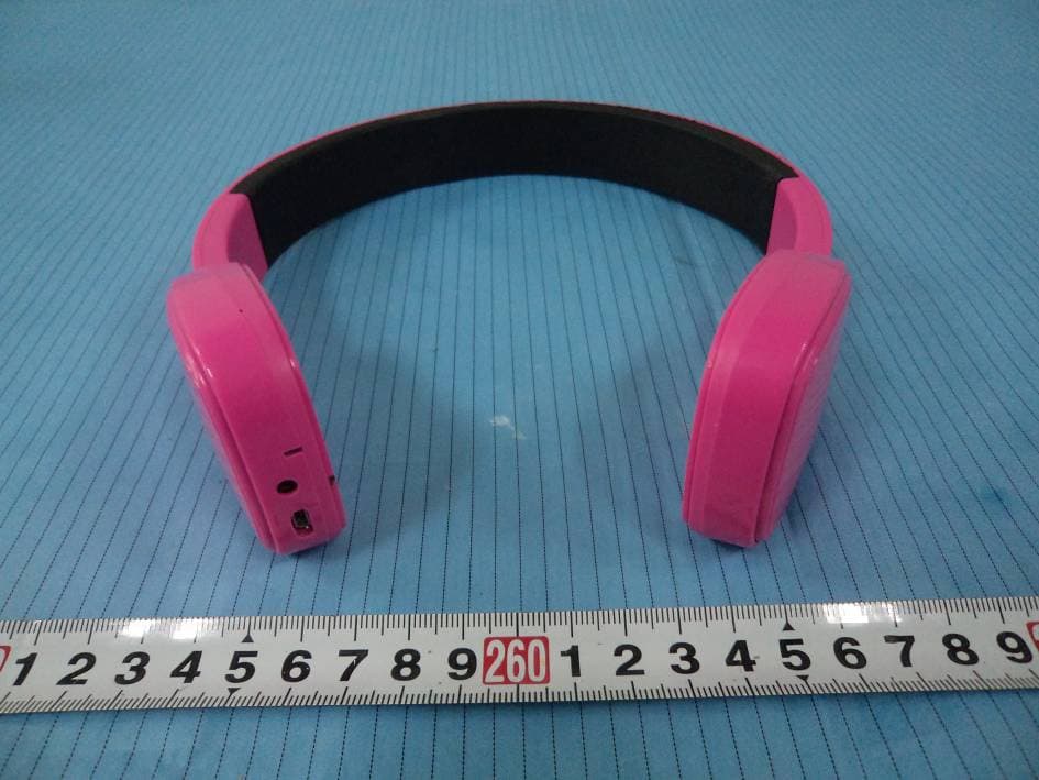
Click to zoom
Application Details
- Equipment Class
- DSS - Part 15 Spread Spectrum Transmitter
- Date of Grant
- Mar 04, 2015
- Application Purpose
- Original Equipment
- Date of Application
- Mar 04, 2015
- Equipment Note
- BT HEADPHONE
- Frequency Range
- 2402.00000000 - 2480.00000000
- Country
- China
Documents & Files
Document Text
Text extracted from the exhibit documents filed with the FCC. Open a document above to read the original.
Users Manual
LBS18 user manual 1. Location of controls A. quick press:previous song long press:increase volume B. Quick: play/pause C. quick press:next song long press: decrease volume D. long press: ON/OFF quick press: answer/end call double press: dial/reject call E. AUX-IN F. USB charging port 2.Pair the headphone with a Bluetooth enabled device Turn the headphone On by long press the power switch, the LED indicator light will quickly blink BLUE. Keep your Bluetooth headphone and Bluetooth enabled device within 3feet of each other during the pairing process, set your mobile phone or other Bluetooth enabled device to search for Bluetooth devices. When the Bluetooth enabled device finds the headphone, select” PBT98”from the list of found devices. If required, enter the password 0000.Select Ok or Yes to pair with your device. After a successful registration, the LED indicator light will slowly blink BLUE. Note: if you would like to connect the headphones to another device, you must unpair the headphones from the currently paired device first. On your device’s Bluetooth settings, select “PBT91”, then select “unpair”. When the headphones have been unpaired, it automatically goes into pairing mode again. 3.using as a wired headphone Connect the one end of the included 3.5mm Aux cable to the Aux In jack on the headphone, and the other end of the cable to an external device’s headphone jack (smartphone,tablet,computer,or MP3 player).Open a media player on your device and click on play to start playing your music. Use the controls on your connected device to control music playback and volume. 4. Charging the Bluetooth headphone Connect the small end of the Micro USB cable to the charging port on the headphone. Connect the large end of the Micro USB cable to your computer’s USB port or an AC adaptor (not included). The LED indicator light turns RED when charging. It will turn off when fully charged. 5. FCC warning Any Changes or modifications not expressly approved by the party responsible for compliance could void the user's authority to operate the equipment. This device complies with part 15 of the FCC Rules. Operation is subject to the following two conditions: (1) This device may not cause harmful interference, and (2) this device must accept any interference received, including interference that may cause undesired operation. This equipment complies with FCC radiation exposure limits set forth for an uncontrolled environment.
External Photos
EXHIBIT B - EUT EXTERNAL PHOTOGRAPHS EUT – Front View EUT – Rear View EUT – Top View EUT – Bottom View EUT – Left Side View EUT – Right Side View
ID Label/Location Info
EXHIBIT A - FCC ID LABEL AND LOCATION FCC ID Label FCC ID Label Location Information The label shown shall be permanently affixed at a conspicuous location on the device and be readily visible to the user at the time purchase (Labeling requirements per 2.925)
Internal Photos
EXHIBIT C - EUT INTERNAL PHOTOGRAPHS EUT –Cover off View EUT – Main Board Top View EUT – Main Board Bottom View EUT – Antenna View BT Antenna EUT – Battery Front View EUT – Battery Rear View
Test Report
Note: This test report is prepared for the customer shown above and for the equipment described herein. It may not be duplicated or used in part without prior written consent from Bay Area Compliance Laboratories Corp. FCC PART 15.247 TEST REPORT For Shenzhen Linpa Technology Co., Ltd 114, C8, Flavor Commercial Street, Vanke Dream Town Longgang District,Shenzhen City, China FCC ID: GTOLBS18 Report Type: Original Report Product Type: BT HEADPHONE Test Engineer: Simon Wang Report Number: RSZ150205013 -00 Report Date: 2015- 02-15 Reviewed By: Jimmy Xiao RF Engineer Prepared By: Bay Area Compliance Laboratories Corp. (Shenzhen) 6/F, the 3rd Phase of WanLi Industrial Building ShiHua Road, FuTian Free Trade Zone Shenzhen, Guangdong, China Tel: +86-755-33320018 Fax: +86-755-33320008 www.baclcorp.com.cn Bay Area Compliance Laboratories Corp. (Shenzhen) Report No.: RSZ150205013-00 FCC Part 15.247 Page 2 of 64 TABLE OF CONTENTS GENERAL INFORMATION ....................................................................................................................................... 4 PRODUCT DESCRIPTION FOR EQUIPMENT UNDER TEST (EUT) ..................................................................................... 4 OBJECTIVE ................................................................................................................................................................... 4 RELATED SUBMITTAL(S)/GRANT(S) ............................................................................................................................. 4 TEST METHODOLOGY .................................................................................................................................................. 4 TEST FACILITY ............................................................................................................................................................. 5 SYSTEM TEST CONFIGURATION .......................................................................................................................... 6 DESCRIPTION OF TEST CONFIGURATION ...................................................................................................................... 6 EUT EXERCISE SOFTWARE .......................................................................................................................................... 6 SPECIAL ACCESSORIES ................................................................................................................................................. 6 EQUIPMENT MODIFICATIONS ....................................................................................................................................... 6 SUPPORT EQUIPMENT LIST AND DETAILS .................................................................................................................... 6 EXTERNAL I/O CABLE .................................................................................................................................................. 7 BLOCK DIAGRAM OF TEST SETUP ................................................................................................................................ 7 SUMMARY OF TEST RESULTS ............................................................................................................................... 8 FCC §15.247 (i) & §2.1093 – RF EXPOSURE ............................................................................................................ 9 APPLICABLE STANDARD .............................................................................................................................................. 9 FCC §15.203 – ANTENNA REQUIREMENT .......................................................................................................... 10 APPLICABLE STANDARD ............................................................................................................................................ 10 ANTENNA CONNECTOR CONSTRUCTION .................................................................................................................... 10 FCC §15.207 (a) – AC LINE CONDUCTED EMISSIONS ..................................................................................... 11 APPLICABLE STANDARD ............................................................................................................................................ 11 MEASUREMENT UNCERTAINTY .................................................................................................................................. 11 EUT SETUP ................................................................................................................................................................ 11 EMI TEST RECEIVER SETUP ....................................................................................................................................... 12 TEST PROCEDURE ...................................................................................................................................................... 12 TEST EQUIPMENT LIST AND DETAILS ......................................................................................................................... 12 CORRECTED FACTOR & MARGIN CALCULATION ....................................................................................................... 12 TEST RESULTS SUMMARY .......................................................................................................................................... 13 TEST DATA ................................................................................................................................................................ 13 FCC §15.205, §15.209 & §15.247(d) – RADIATED EMISSIONS ........................................................................... 16 APPLICABLE STANDARD ....................................................................................................................................…
Text truncated - open the document above for the full version.
Test Setup Photos
EXHIBIT D - TEST SETUP PHOTOGRAPHS Conducted Emissions - Front View Conducted Emissions - Side View Radiated Emissions – Front View (30-1000 MHz) Radiated Emissions – Rear View (30-1000 MHz) Radiated Emissions – Front View (1-25 GHz) Radiated Emissions – Rear View (1-25 GHz)
Contact Information
Applicant
Sha Guo
Test Firm
Bay Area Compliance Laboratory Corp. (Shenzhen)John Chan
Technical Specifications
| # | Rule Parts | Frequency Range | Power Output |
|---|---|---|---|
| 1 | 15C | 2.40 GHz - 2.48 GHz | 3.40 mW |
Other Applications from Shenzhen Linpa Technology Co.,Ltd
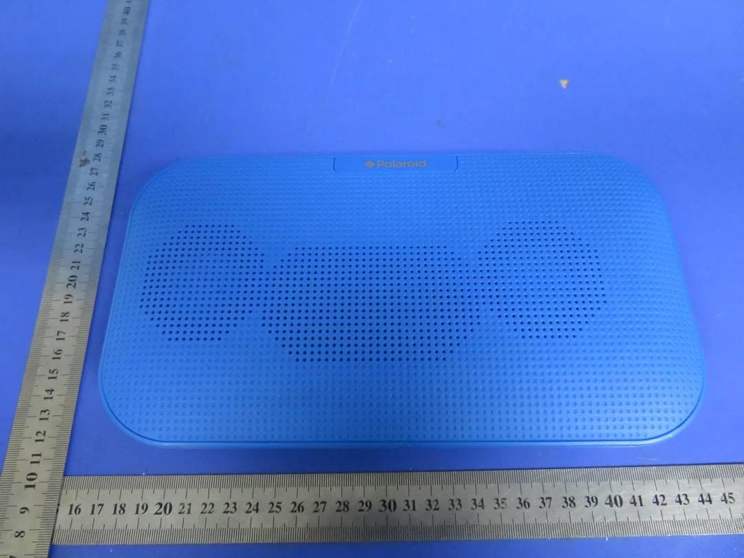
GTOLBS51
Jan 24, 2016Bluetooth Speaker
Equipment Class
DSS - Part 15 Spread Spectrum Transmitter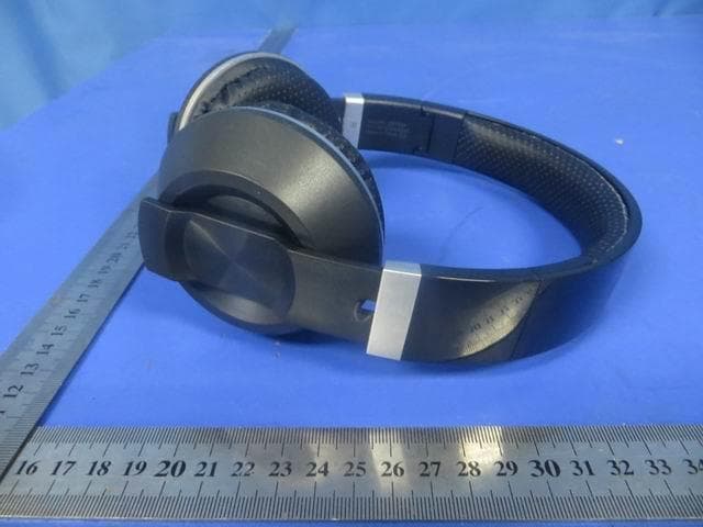
GTOLBS45
Dec 20, 2015Bluetooth Earphone
Equipment Class
DSS - Part 15 Spread Spectrum Transmitter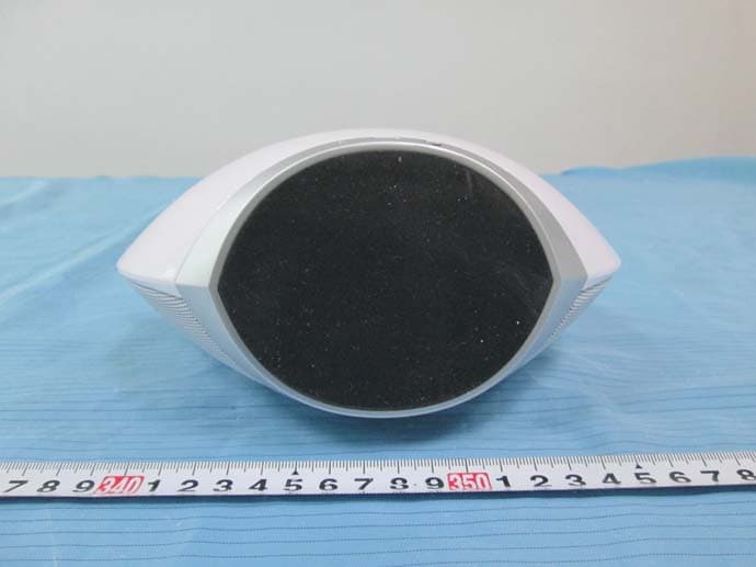
GTOLBS46
Nov 21, 2015BT Soundbox
Equipment Class
DSS - Part 15 Spread Spectrum Transmitter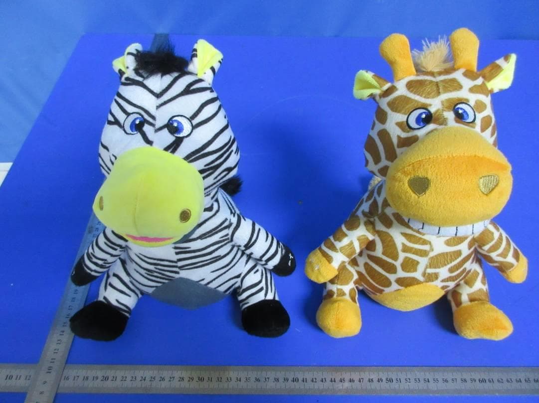
GTOLBS40
Oct 04, 2015Plush Pal Wireless Speaker
Equipment Class
DSS - Part 15 Spread Spectrum Transmitter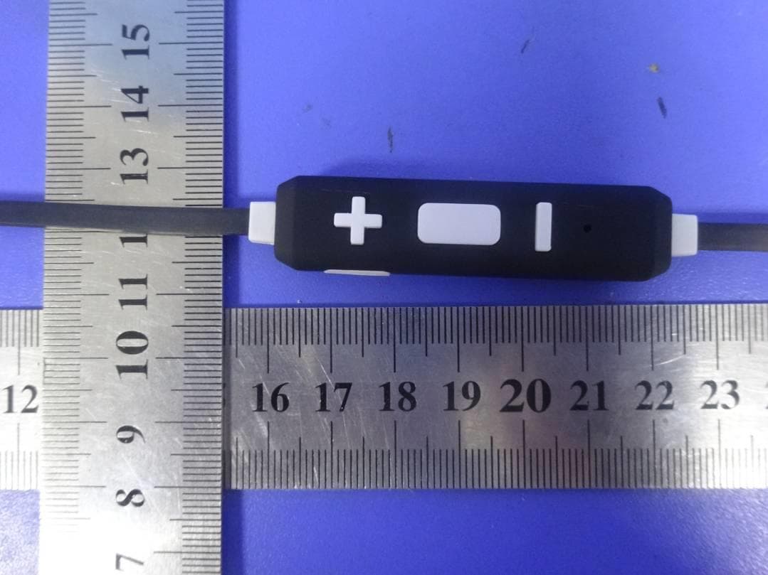
GTOLBS32
Aug 24, 2015Bluetooth Headset
Equipment Class
DSS - Part 15 Spread Spectrum Transmitter