GTS315TWireless Rain Gauge
RainWise Inc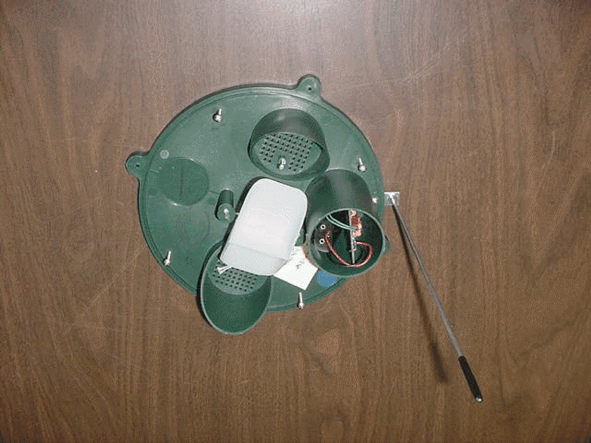
Click to zoom
Application Details
- Equipment Class
- DSC - Part 15 Security/Remote Control Transmitter
- Date of Grant
- May 17, 2001
- Application Purpose
- Original Equipment
- Date of Application
- May 17, 2001
- Equipment Note
- Wireless Rain Gauge
- Frequency Range
- 315.00000000 - 315.00000000
- Company
- RainWise Inc
- Country
- United States
Documents & Files
Document Text
Text extracted from the exhibit documents filed with the FCC. Open a document above to read the original.
Users Manual
Installation and Operation of the RainWise Rainew TM Wireless Rain Gauge 1. The rain gauge has been designed and tested to operate at 150 feet line of sight. However, this distance may be shortened dramatically by obstacles, power lines and the new energy efficient window glass. In order to obtain consistent, reliable operation the following guidelines must be observed: a. Try to locate the gauge in an open spot away from trees, but as close to the house as possible. b. The gauge must be mounted on a flat surface at least one foot above the ground. The reason for this is that the ground acts like shunt for the transmitter antenna and this drastically reduces the operating distance. c. Locate the receiver/counter inside the house on an outside wall as close to the gauge as possible. Note that any changes to the transmitting circuit board assembly or antenna are not approved by RainWise Inc. and could void the users authority to operate the Wireless Rain Gage. 2. Back out the screws holding the collector in place until it can be rotated to a point where it may be removed. Remove the collector. Do not fasten the gauge in place yet. 3. Remove the blue cap covering the transmitter and remove it from the base cup. Leave the desiccant in place. 4. Lift out the battery holder and install 2 alkaline AA batteries. 5. Replace the blue cap over the transmitter cup. 6. Position the rain gauge so that the antenna is aimed at the house. The strongest radio signal is achieved if the antenna is not obstructed by the gauge. 7. Install 2 “C” batteries in the base of the receiver/counter by removing the cover. Observe the polarity. Replace the cover. NOTE: The Counter displays also uses #357 button cells, which are Included. 8. Zero the counter/s by pressing the button on the front. 9. Slowly tip bucket back and forth by hand. Do this exactly 10 times. Within one minute you should see a count 10 counts on the 100 ths display and 1 on the 10ths (for dual displays). The transmitter is activated every tip and the rainfall count is sent to the receiver. Continue tipping until you have at least 20 tips. If the count on the counter equals the number of bucket tips then the location for the gauge is okay. If the counter does not count or if the count is less than the number of tips, the gauge must be moved to a different location. . . either closer or sideways or both. Be sure to orient the gauge to the house as shown in Figure #1. 10. When a satisfactory location is obtained you may fasten the gauge in place with the four screws provided. 11. Place the collector over the base and rotate until the lugs are lined up with the four screws. Tighten the four screws 12. For dual counters, disconnect a battery in the receiver for approximately 5 seconds. Replace the cover and reset the counters. This completes the installation. If you have a problem with your Rainew wireless gauge, call the factory at 1-800-762-5723. Do not contact the dealer or catalog Figure #1 \DOCS\INSTRUCT\rain gauge new radio WARRANTY Our rain gauges have a lifetime warranty on the gauge. The electronic portions (transmitter, receivers and counters) are guaranteed for one year. If your rain gauge ever requires repairs, you must enclose $6.50 for shipping and handling. Make checks payable to RainWise, Inc.. There is never a charge for gauge repairs, but if the electronic portion is out of warranty, we will call you and advise the cost to repair. Be sure to include your phone number and return address with your gauge.
Block Diagram
DWG. NO. DRAWN BY: DATE: MATERIAL: USED ON: TITLE: REVISION: PHASE SHIFT NETWORK SAW OSCILLATOR 50 OHM RF OUT (ANT.) OUTPUT ISOLATION AND FILTER RF AMPLIFIER DATA I N TRANSMITTER - 315 Mhz WB BLK315T 4-17-01 Rain Gauge Transmitter ® ANTENNA 34.8 R7 26.1 R5 26.1 R4 3 meg 32.768Khz April 17 2001 Data TRANSMITTER 10 db attenuation Ground 3.0kHz ENCODER TE rgblock.s01 mv RG BLOCK MICROPROCESSOR RAINGAGE AB CD 4 3 2 1 DCBA 1 2 3 4 ofSheet Drawn by RevNumber Title Size A Date Filename
ID Label/Location Info
TRANSMITTER LABEL This device complies with Part 15 of FCC Rules. Operation is subject to the following two conditions: (1) This device must not cause harmful interference. (2) This device must accept any interference received, including interference that may cause undesired operation. 2 " 3/4 " FCC ID: GTS315T ®
Operational Description
Description of the Circuit Functions The following is a description of the RainWise Inc. wireless rain gauge. Please refer to the drawing “Wireless Rain Gauge”. The electronic components consist of a microprocessor operating at 32.768kHz, a Holtek HT12E encoder chip operating at approximately 3.0kHz and a LINX Technology Inc. TXM-315-LC SAW type transmitter operating at 315mHz. The microprocessor monitors the tipping bucket type of rain gauge. For every tip of the bucket, the microprocessor pulls the TE line of the ENCODER low which activates the transmitter. The transmitter outputs for four seconds the pulse recognition code described below. A 10-dB “T” pad resistor network is placed between the output of the transmitter and the antenna. The receiving unit detects the pulse recognition code using a Holtek HT12D or similar decoder. The decoder output causes a digital counter to increase. Therefore, the pulse recognition code increases a counter for each tip of the rain gage bucket. For rain gages calibrated in inches, the counter increases by .01 inches. For metric calibrated rain gages, the increment is 1 millimeter. Driven by the Encoder, the transmitter continuously outputs a pulse recognition code of 13 bits. There is an off time approximately equal to the time for the code to be output. The 13-bit code consists of 7 bits, which have an approximate on time of 1.0 millisecond, and an off time of 2.0 milliseconds. Bits 8 and 9 have an on time of approximately 2.0 milliseconds and an off time of 1.0 millisecond. The last four bits of the recognition code have an approximate on time of 1.0 millisecond and an off time of 2.0 milliseconds. The 13-bit code is sent every 71 milliseconds.
Schematics
GND C2 22pF C1 22pF 32k X1 A1 26.1 R5 34.8 R7 26.1 R4 BATT 3.0v GND 1N4001 D2 VDD GND C4 .1uF VDD VDD .1uF C5 GND VDD U3 VDD 1 OSC1 2 OSC2 3 MCLR 4 T0CKI 5 GP1 6 GP0 7 VSS 8 U2 A7 8 A6 7 A5 6 A4 5 A3 4 A2 3 A1 2 A0 1 AD8 10 AD9 11 AD10 12 AD11 13 TE 14 OSC2 15 OSC1 16 DOUT 17 R1 3.0 meg GND 12 12 GND GND GND GND GND R3 10 C6 10uF U1 GND 8 VCC 7 GND 6 RF OUT 5 IADJ/GND 4 DATA IN 2 GND 3 GND 1 VDD 10k R2 .1uF C3 GND VDD GND J1 1 2 Encoder MPU Transmitter Open Reed Switch Rain gage is a Normally wirelinx.s01 mv 10 DB Attenuation Wireless Raingage (LINX) April 1, 2001 AB CD 4 3 2 1 DCBA 1 2 3 4 ofSheet Drawn by RevNumber Title Size A Date Filename
Test Report
May 8, 2001 Elite Electronic Engineering, Inc. 1516 Center Circle Downers Grove, IL 60515 Attn:Mr. Richard King Dear Richard: Enclosed you will find an application for Certification of a Rainwise 315MHz Wireless Rain Gauge FCC ID: GTS315T. Certification is requested to the requirements of Part 15, Subpart C of the Commission’s rules. This application is being filed by Retlif Testing Laboratories on behalf of Rainwise, Inc. I trust that you will find the enclosed application to be complete; however, should you have any questions or require any additional information, please feel free to contact us. Very truly yours, RETLIF TESTING LABORATORIES Scott Wentworth Manager Enc. (as stated) Test Report No. R-3728N FCC ID: GTS315T APPLICANT Rainwise, Inc. 25 Federal Street Bar Harbor, ME 04609 MANUFACTURER SAME TEST SPECIFICATION: FCC Rules and Regulations Part 15, Subpart C, Para. 15.231 TEST PROCEDURE: ANSI C63.4:1992 TEST SAMPLE DESCRIPTION BRANDNAME: Rainwise MODEL: N/A TYPE: Wireless Rain Gauge POWER REQUIREMENTS: 3VDC Internal Batteries (2 AA) (Tested With New Batteries) FREQUENCY OF OPERATION: 315MHz MODULATION: Pulsed (On/Off Keying) TYPE OF TRANSMISSION: Control Signal (Pulse Recognition Codes) FCC ID: GTS315T APPLICABLE RULE SECTION: Part 15, Subpart C, Section 15.231 TESTS PERFORMED Spurious Emissions Field Strength of Fundamental Occupied Bandwidth, 0.25% of Fundamental Frequency Duty Cycle Determination TEST SAMPLE OPERATION The device is automatically operated during rainfall and is used to monitor rainfall amounts. When activated the device transmits a pulse recognition code packet consisting of 13 pulses. Normal operation of the EUT complies with the parameters required in Part 15, Subpart C, Section 15.231. For testing purposes only the EUT was configured to continuously transmit. Test Report No. R-3728N FCC ID: GTS315T TEST SAMPLE / TEST PROGRAM CThe transmitter is automatically activated and ceases transmission after 4 seconds. CThe transmitter does not perform periodic transmissions at regularly predetermined intervals. CThe device is not employed for RC purposes involving security. CThe fundamental field strength at 315MHz did not exceed 6041.68 μV/M (Average) at a test distance of 3 meters. CThe field strength of harmonic and spurious emissions did not exceed 604.17μV/M or 500μV/M as applicable. CThe bandwidth of emissions did not exceed 0.25% of the operating frequency and was determined as follows: Fundamental Frequency=315MHz 0.25% of Center Frequency=787.5kHz 787.5 divided by 2=393.75kHz Bandwidth Range=Fundamental Frequency + and - 393.75kHz 315MHz - 393.75kHz=314.61MHz 315MHz +393.75kHz=315.39MHz Bandwidth Range=314.61MHz - 315.39MHz CThe device uses an external permanently attached antenna. CRadiated Emissions from the EUT were measured in all three axis. Worst case emissions were found with the EUT in the vertical upright position. This orientation is also the position in which the device will normally be used. The attached Radiated Emissions test data is representative of this worst case orientation. Test Report No. R-3728N FCC ID: GTS315T TEST SAMPLE / TEST PROGRAM (continued) DETERMINATION OF FIELD STRENGTH LIMITS The field strength limits shown below were calculated as instructed in Section 15.231. Fundamental Frequency: 315MHz Where F is the frequency in MHz, the formula for calculating the maximum permitted fundamental field strength for the band 260-470MHz, μV/m at 3 meters is as follows: 41.6667(F) - 7083.3333 =Field Strength Limit (μV/m) 41.6667 x 315=13125.011 13125.001- 7083.3333=6041.68 Field Strength Limit=6041.68 μV/m The maximum permitted unwanted emission level is 20dB below the maximum permitted fundamental level. The maximum permitted level of the peak emission is 20dB above the maximum permitted average limit. Test Report No. R-3728N FCC ID: GTS315T TEST SAMPLE / TEST PROGRAM (continued) DETERMINATION OF DUTY CYCLE The transmitter controls were adjusted to maximize the transmitted duty cycle. The analyzer was set for a frequency span of 0Hz. The sweep time was then adjusted in order to display one full pulse train. The transmitter on time was then summed and compared to the time for one full cycle in order to obtain the duty cycle. Fundamental Frequency: 315MHz Transmitter On Time=13.96milliseconds (maximum) Transmitter Cycle Time=70.74 milliseconds Transmitter Duty Cycle=19.73% On Time divided by Cycle Time=Duty Cycle Factor 13.96 divided by 70.74=0.1973 0.1973 converted to dB (LOG 10 .1973)20=-14.09dB Duty Cycle Factor=-14.09dB Duty Cycle Factor Determination Plots are included with this application as a separate attachment. SPECTRUM ANALYZER Due to the nature of the emissions being measured, care was taken to ensure that the resolution bandwidth of the spectrum analyzer was adequate to provide accurate measurements. GENERAL NOTES 1.All readings were taken utilizing a peak detector function at a test distance of 3 meters. 2.The duty cycle factor was applied to the peak readings in order to determine the average value of the emissions. 3.The frequency range was scanned from 9kHz to 3.2GHz. Emission levels closest to the specified limit are listed on the attached data sheet. Test Report No. R-3728N FCC ID: GTS315T EQUIPMENT LISTS Field Strength of Fundamental ENTypeManufacturerDescriptionModel No.Cal DateDue Date 4202BiconilogEMCO26 MHz - 2 GHz31427/10/007/10/01 4895Spectrum AnalyzerHewlett Packard9kHz - 22GHz8593EM2/17/012/17/02 4921Graphics PlotterHewlett PackardN/A7550A4/25/014/25/02 713EMI Test ReceiverRohde & Schwarz20 Hz - 26.5 GHzESI263/9/013/9/02 Occupied Bandwidth ENTypeManufacturerDescriptionModel No.Cal DateDue Date 713EMI Test ReceiverRohde & Schwarz20 Hz - 26.5 GHzESI263/9/013/9/02 Spurious Emissions ENTypeManufacturerDescriptionModel No.Cal DateDue Date 3116Pre-AmplifierMiteq0.1 GHz - 18 GHzAFS42-3511/7/0011/7/01 3117Power SupplyB&K Precision0-30 Vdc, 3.0 A16302/23/012/23/02 3258Double Ridge GuideEMCO1 - 18 GHz31154/6/014/6/02 4202Bic…
Text truncated - open the document above for the full version.
Contact Information
Applicant
John S. Baer(President)
207-288-5169Fax: 207-288-3477
Technical Contact
Retlif Testin LaboratoriesJohn Monahan
[email protected](603) 497-4600
101 New Boston Road · Goffstown, New Hampshire · United States
Non-Technical Contact
Retlif Testin LaboratoriesScott A Wentworth
[email protected](603) 497-4600
Test Firm
Retlif Testing LaboratoriesScott Wentworth
Technical Specifications
| # | Rule Parts | Frequency Range | Power Output |
|---|---|---|---|
| 1 | 15.231 | 315 MHz - 315 MHz | - |
Other Applications from RainWise Inc
GTS418T
Jun 29, 1998DXX - Part 15 Low Power Communication Device Transmitter
Equipment Class
DXX - Part 15 Low Power Communication Device TransmitterGTS418R
Jun 22, 1998CYY - Communications Receiver used w/Pt 15 Transmitter
Equipment Class
CYY - Communications Receiver used w/Pt 15 TransmitterGTS3S8WS-1000-CC
Dec 01, 1987JBP - Part 15 Class B Computing Device Peripheral
Equipment Class
JBP - Part 15 Class B Computing Device Peripheral