GV319422UPWireless Mouse
ACCO Brands, Inc.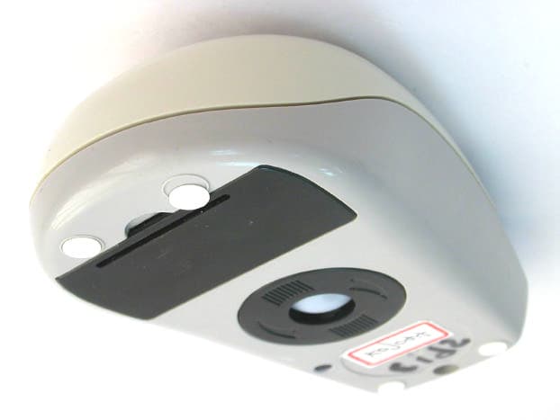
Click to zoom
Application Details
- Equipment Class
- DXX - Part 15 Low Power Communication Device Transmitter
- Date of Grant
- Mar 30, 2003
- Application Purpose
- Original Equipment
- Date of Application
- Mar 30, 2003
- Equipment Note
- Wireless Mouse
- Frequency Range
- 26.96000000 - 27.28000000
- Company
- ACCO Brands, Inc.
- Country
- United States
Documents & Files
Document Text
Text extracted from the exhibit documents filed with the FCC. Open a document above to read the original.
Users Manual
ValuMouse ™ Wireless 3 Button Installation Instructions 5331ValuMouseWirels 17/1/03 3:23 pm Page I WARNING This device complies with Part 15 of the FCC Rules. Operation is subject to the following two conditions : (1) this device may not cause harmful interference, and (2) this device must accept any interference received, including interference that may cause undesired operation. CAUTION: changes or modifications not expressly approved by the party responsible for compliance could void the user’s authority to operate the equipment. 5331ValuMouseWirels 17/1/03 3:23 pm Page II English Installation Instructions ValuMouse Wireless • 1 1. Select channel I or II on the mouse 2. Plug the USB/PS/2 Receiver into your computer 3. Press the connect button on the top of the Receiver 4. Press the Connect Button on the Base of the Mouse Battery compartment Connect Button Receiver Connect Button 5331ValuMouseWirels 17/1/03 3:23 pm Page 1 Connecting to a PC To connect to aDo this: USB portPlug the cord into your computer’s USB port or a USB port on a hub connected to your computer. You do not need to turn off your computer before connecting or disconnecting a USB device. PS/2 mouse port1. Turn off your computer. 2. Plug the cable into the adapter, then plug the adapter into the computer’s PS/2 port. 3. Reboot your computer. Connecting to a Macintosh computer To connect to aDo this: USB portPlug the cord into your computer’s USB port. You may also use the spare USB port on your keyboard, or a USB port on a hub connected to your computer. You do not need to turn off your computer before connecting or disconnecting a USB device. Installation Instructions 2 • ValuMouse Wireless Connecting your ValuMouse Wireless Your ValuMouse Wireless has a USB connector, which can work with both PCs and Macintosh® computers and a PS/2 adapter for PCs. 5331ValuMouseWirels 17/1/03 3:23 pm Page 2 Installing the Software If you want to customise the use of the middle button, you need to install the software that accompanied the mouse. Please proceed to proper installation based on the version of Operating Software installed on your Computer: Installing software under Windows 95 or 98 Insert the software disc in your floppy disc drive, click the Start button, choose Run and type “a:\setup”, click OK and follow the instructions on screen. Installing software under Windows NT 4.0: Log in as Administrator or as a user who has Administrator privileges. Follow the same procedure as outlined for installation under Windows 95. Installation software under Windows NT 3.5x and Windows 3.1x: From the File menu in Programme Manager, Choose Run. In the dialogue box, type “a:\setup”, and click OK, then follow the instructions on screen. Installing software under DOS: Refer to “readme” file on the software disc. Installation Instructions ValuMouse Wireless • 3 English 5331ValuMouseWirels 17/1/03 3:23 pm Page 3 Upon completion of software installation PS/2 users – When the mouse is connected to the PS/2 port, the ValuMouse Wireless software will automatically enable the middle button functionality (specific to the application being used) under Win 3.1x, Win95 and Win98, WinNT 3.5x and WinNT 4.0x. Customising the Use of the Middle Button If you would like to customise the specific functionality of the middle button, follow these instructions based on the Windows version on your PC. Under Windows 95, 98 and NT 4.0x Right click on the mouse icon in the system folder and click on Open. This will bring up the Kensington ValuMouse Wireless Control panel. Click on the pulldown menu in the Control Panel, pick a function from the list provided and click on “OK” button. Installation Instructions 4 • ValuMouse Wireless 5331ValuMouseWirels 17/1/03 3:23 pm Page 4 Under Windows 3.1x and NT 3.5x Double click on the mouse icon on the desktop. This will bring up the Kensington ValuMouse Wireless control panel. Click on the pulldown menu, pick a function from the list provided and click on “OK” button. Uninstalling Kensington ValuMouse Wireless software Refer to “readme” file on the software disc. Installation Instructions ValuMouse Wireless • 5 English 5331ValuMouseWirels 17/1/03 3:23 pm Page 5 Trouble Shooting Symptom:No mouse movement. Possible Causes:(1) Make sure the mouse is securely plugged in the PS/2 or USB port. (2) Make sure you have installed Kensington ValuMouse Wireless software or the standard Microsoft mouse drivers included with your Windows operating system. Symptom:The cursor on the screen remains at one spot or moves erratically. Possible Causes:Check the mouse cable for any breaks or sharp twists. Examine the cable closely where it connects to the mouse. Symptom:Mouse movement does not produce corresponding cursor movement or there is a brief pause during movement. Solution:Clean the silicone rubber-coated ball and rollers. For additional assistance, please visit www.valumouse.kensington.com Trouble Shooting 6 • ValuMouse Wireless 5331ValuMouseWirels 17/1/03 3:23 pm Page 6 5-Year Warranty KENSINGTON TECHNOLOGY GROUP (”KENSINGTON”) warrants this PRODUCT against defects in material and workmanship under normal use and service for five years from the original date of purchase. KENSINGTON, at its option, shall repair or replace the defective unit covered by this warranty. Please retain the dated sales receipt as evidence of the date of purchase. You will need it for any warranty service. In order to keep this warranty in effect, the product must have been handled and used as prescribed in the instructions accompanying this warranty. This warranty does not cover any damage due to accident, misuse, abuse or negligence. This warranty is value only if the product is used on the computer or system specified on the product box. Please check product box for details, or e-mail technical support at [email protected]. Repair or replacement, as provided under this warranty, is your exclusive remedy. KENSINGTON shall not be liable for any incidental or…
Text truncated - open the document above for the full version.
Block Diagram
1234 A B C D 4321 D C B A 1 15016. ,235 ,, , 2 A 12-Dec-200211:39:27D:\WIN_BACK\CHIC\MOUSE\C195\\C195TX.SCH Title Size:Number: Date:File: Revision: SheetofTime: A4 C-195 TX-BLOCK DIAGRAM BATTERY 1.5V BATTERY 1.5V 6MHz VCC VCC VCC VCC RF TX PARTS VCC ENABLE DATA OUT X AXIS SENSER ENCODER ENCODER SENSER Y AXIS CPU 3 BUTTON VCC ENCODER Z AXIS BATTERY LOW DETECTOR VCC ANTENNA S1 CHANNEL SW 27.095Mhz 27.045Mhz 1234 A B C D 4321 D C B A 1 15016. ,235 ,, , 2 A 12-Dec-200211:38:30D:\WIN_BACK\CHIC\MOUSE\C195\\C195RX.SCH Title Size:Number: Date:File: Revision: SheetofTime: A4 C-195 RX-BLOCK DIAGRAM ANTENNA MIXER IF FILTER DETECTOR CRYSTAL OSC 455KHz (RF RX PARTS) DATA S1 AUTO CHANNEL MICRO CONTROLLER RF LED LINK BUTTON EEPROM PS2/USB ADAPTOR USBPS2 27.5Mhz27.55Mhz
ID Label/Location Info
LABEL Format: This device complies with Part 15 of the FCC Rules Operation is subject to the following two conditions: (1) This device may not cause harmful interference, and (2) This device must accept any interference received, including interference that may cause undesired operation. FCC ID : GV319422UP Model No.: 19422 LABEL Size: 20X 10 mm LABEL Position: LABEL
RF Exposure Info
Mouse Antenna Spec
Schematics
1234 A B C D 4321 D C B A 15016F 235 EPC-195003201.0 12-Dec-200211:48:0319500320.sch Title Size:Number: Date:File: Revision: Sheet2 OF 3Time: A4 C195 2 Channel Transmitter Behind RA2 1 RA3 2 RTCC 3 MCLR 4 GND 5 RB0 6 RB1 7 RB2 8 RB3 9 RB4 10 RB5 11 RB6 12 RB7 13 VCC 14 SC0 15 SC1 16 RA0 17 RA1 18 U1 MDT2010-ES 12345678 J1 HEADER 8 D5 NC D6 4148 D7 4148 D8 4148 3 2 1 5 4 X3(Y) PT 3 2 1 5 4 X2(X) PT R14 330K R11 330K R10 or R10A 240 R12 330K R13 330K R9 or R9A 240 C7 220pF C6 220pF C5 220pF C4 220pF C3 1uF R4 51K C13 NC Q1 C945 R18 10K R16 330K RB6 C11 1uF C12 1uF VCC VCC R2 330K R1 330K VCC X1 6.0MHz R3 1M C1 15pF C2 15pF C10 56pF R8 10 3 1 2 VCCVCC RB6 VCC P2 BAT P1 BAT R20 10K C30 NC X20 C23 68pF C24 18pF 5% C25 30pF R23 1.2K R25 100K Q21 NPN1 Q20 NPN1 R26 100K RB6 C32 1uF Q22 NPN1 C21 0 C22 15pF R27 47 C20 103 Q3 A733 R5 10K 2.2V VCC C31 1uF C9 NC X11 S1SGB-12 R28 NC C8 VCC R6 100 LED 2.2V2.2V2.2V R22 NC NC 27.095mhz27.045 mhz VO 2 SW 1 GND 3 HT7024A IN 2 GND 1 OUT 3 RT9161-22CX + C33 100uF + C34 10uF or Nc U2 U3 1234 A B C D 4321 D C B A 15016F 235 EPC-19500319V 0.1 12-Dec-200211:42:1319500319.sch Title Size:Number: Date:File: Revision: Sheet1 OF 3Time: A4 C195 2 Channel Transmitter Front SW1LM SW3 R SW2 SW4 SW5 ID SW6 12345678 J3 HEADER 8 D4 NC D3 1N4148 D2 1N4148 D1 1N4148 A 1 B 2 C 3 P1 ENCODER 2 1 2 1 22 2 2 11 1 1 NCNC 123456 A B C D 654321 D C B A 1 150 16. ,235 , , , 1 EPC-130E0306 3.0 12-Dec-200211:40:54130E0306.sch Title Size:Number: Date:File: Revision: SheetofTime: A4 C195 2 Channel Upcombo Receiver C1 104 + C4 10uF VCCVCC VCC D- D+ A0 1 A1 2 A2 3 GND 4 SDA 5 SCL 6 TEST 7 VCC 8 U2 AT24C02 VCC R2 560 R3 1.3K R4 1.3K D+/SCLK 13 P1.1 14 XTALIN 9 XTALOUT 10 VCC 11 VREG 8 P00 1 P01 2 P02 3 P03 4 P04 18 P05 17 P10 5 P06 16 VSS 6 P07 15 VPP 7 D-/SDATA 12 U1 CY7C63723 DATA SW1 SW-PB R5 1.3K CH1 CH2 CH1 CH2 Q1 3904 Q2 3904 C3 1000pF C6 27pFC7 27pF C8 0.1uF C9 0.1uF C10 0.1uF C11 0.01uF R7 27K R8 3.3K X3 27.550MHz X2 27.50MHz 12 F1 455KHZ FILTER R9 4.7K C12 22pF X4 455C28 R10 100K C14 0.1uF D1 1N4148 R11 NC OSCB 1 OSCE 2 MBCO 3 VCC 4 IFI 5 DEC1 6 DEC2 7 BUAD 8 AUTO 9 FI 10 FO 11 SQI 12 SCAN 13 MUTE 14 GND 15 MOCI 16 MC3361 U3 MC3361 Q4 2N3904 DATA +C13 10uF VCC L1 4.7uH INDUCTOR C5 33PF ANT R12NC R13NC LED V+ L2 BEAD 600 or NC 1 2 3 4 5 WAFER HEADER 5 SHIELD G Q3 2N3904 R1 22R VCC 12 J1 JUMPER VCC1 R6 NC C15 4700pF
Test Report
Test Report ------------------------------------------------------------------------------- 2/15 Report No.: K0715045 Training Research Co., Ltd., TEL: 886-2-26461146, Fax: 886-2-26461778 Contents Chapter 1 Introduction Description of EUT...................................................................................................................3 Configuration of Test Setup......................................................................................................4 List of Support Equipment........................................................................................................6 Chapter 2 Conducted Emission Test Test Condition and Setup..........................................................................................................8 Chapter 3 Peak Power Measurement (Frequency Band: 26.96 ~ 27.28) Test Setup..................................................................................................................................9 Test Procedure...........................................................................................................................9 Chapter 4 Radiated Emission Test Test Condition and Setup.........................................................................................................10 Radiated Test Placement..........................................................................................................11 Appendix A: Peak Power and Radiated test result........................................................................................12 Appendix B: Band Edge of Measurement.....................................................................................................14 Test Report ------------------------------------------------------------------------------- 3/15 Report No.: K0715045 Training Research Co., Ltd., TEL: 886-2-26461146, Fax: 886-2-26461778 Chapter 1 Introduction Description of EUT: EUT : Wireless Mouse and Receiver Model No. : 19422 Product name : Valu Mouse Wireless Frequency Range : 26.96 – 27.28 MHz Power Type : Transmitter: Powered by two 1.5VDC AA batteries Receiver: Powered by PC *This EUT has two channels (each with 256 IDs): 1. 27.0450 MHz 2. 27.0950 MHz Test method: Pretest was found that the emission of operating mode is worse than standby mode. So, The final test is made at the operating mode. During the measurement, there are two modes with different channels tested: “USB Interface CH-1”, “USB Interface CH-2”, “PS/2 Interface CH-1” and “USB Interface CH-2” modes. During testing, the EUT was operated at “transmitting”, “receiving” mode simultaneously. The test voltage is 230Vac / 50Hz. The radiation test was found out the testing mode: “USB Interface CH-1” was the worst case and we only recorded worse cases in this report. While testing, the EUT was made to transmit continuously and adjusted at a position, which transmitted the maximum emission. The test placement as the photographs showed is the worst emission placed. (If the emission is close to the ambient, the resolution BW and view resolution will be reduced and the data will be recorded by detection of maximum hold peak mode.) The testing configuration of test setup is showing in the next page. Test Report ------------------------------------------------------------------------------- 4/15 Report No.: K0715045 Training Research Co., Ltd., TEL: 886-2-26461146, Fax: 886-2-26461778 Configuration of Test Setup (Test Mode: USB Interface) Connections: PC: *Serial Port --- via a 110cm shielded RS-232 cable to an external modem. *Monitor Port --- a monitor with 1.5m length data cable. *Keyboard port --- via a 0.30m long shielded data cable to the receiver. *Mouse port --- a mouse with 1.8m long of data cable. *USB port --- to EUT(Rx). (Each port on PC is connected with suitable device) EUT(Tx): *Put two AA size, 1.5V battery into the battery cell of EUT, powers the subject device. The EUT does not be connected with any product. EUT(Rx): *USB Jack --- with a 140cm long USB cable to the USB port of PC. Power EUT (Rx) Printer Modem PC Monitor Keyboard USB Joystick Mouse EUT (Tx) Test Report ------------------------------------------------------------------------------- 5/15 Report No.: K0715045 Training Research Co., Ltd., TEL: 886-2-26461146, Fax: 886-2-26461778 Configuration of Test Setup (Test Mode: PS/2 Interface) Connections: PC: *Serial Port --- via a 110cm shielded RS-232 cable to an external modem. *Monitor Port --- a monitor with 1.5m length data cable. *Keyboard port --- via a 0.30m long shielded data cable to the receiver. *Mouse port --- to EUT(Rx). *USB port --- a mouse with 1.8m long of data cable. (Each port on PC is connected with suitable device) EUT(Tx): *Put two AA size, 1.5V battery into the battery cell of EUT, powers the subject device. The EUT does not be connected with any product. EUT(Rx): *USB Jack --- with a 140cm long USB cable via a USB to PS/2 adaptor to the Mouse port of PC. Power EUT (Rx) Printer Modem PC Monitor Keyboard USB Joystick USB Mouse EUT (Tx) Test Report ------------------------------------------------------------------------------- 6/15 Report No.: K0715045 Training Research Co., Ltd., TEL: 886-2-26461146, Fax: 886-2-26461778 List of Support Equipment Conducted (Radiated) test: PC : HP Brio 85xx 6/350 Model No. : D6928A Serial No. : SG91801443 FCC ID : Doc Approved Power type : 100 ~ 230VAC / 50 ~ 60Hz, 5A, Switching Power cord : Non-shielded, 2.33m long, Plastic, No ferrite core Monitor : HP pavilion mx70 Model No. : P1283A Serial No. : THTBR00257 FCC ID : DOC Approved Power type : 100 ~ 240V AC 15A 50/60Hz Power cord : Shielded, 1.83m long, No ferrite core Data cable : Shielded, 1.46m (1.80m) long, with two ferrite cores (no ferrite core) Printer : HP Model No. : C2642A Serial No. : SG69A196GV FCC ID : B94C2642X Power type : 230 VAC, 50Hz Power cord : Non-shielded, 2m long, no ferrite core Data cable : Shielded, 1.84m long, no ferrite core Modem : ACEEX Model No. : D…
Text truncated - open the document above for the full version.
Test Setup Photos
Training Research Co., Ltd. 255 Nanyang Street, Shijr, Taipei Hsien 221, Taiwan, R.O.C. TEL: 886-2-26935155 FAX: 886-2-26934440 TRCSince1985 ® Test setup photos: Item Tested: ValuMouse Wireless (Test report no.: K0715045) FCC ID: GV319422UP Test Instruments Configuration of the Spurious Radiated Emissions N/A Test Instruments Configuration of Peak Power Measurement EUT 1M 3M Spectrum Training Research Co., Ltd. 255 Nanyang Street, Shijr, Taipei Hsien 221, Taiwan, R.O.C. TEL: 886-2-26935155 FAX: 886-2-26934440 TRCSince1985 ® Test Instruments Configuration of the Spurious Radiated Emissions Front View of the Test Configuration Rear View of the Test Configuration
Contact Information
Applicant
Benjamin Hsu(Compliance Manager)
Test Firm
Training Research Co., Ltd.Jack Tsai
Technical Specifications
| # | Rule Parts | Frequency Range | Power Output |
|---|---|---|---|
| 1 | 15C | 26.96 MHz - 27.28 MHz | - |
Other Applications from ACCO Brands, Inc.
GV3M01709-K
Nov 28, 2024KB270 EQ Rechargeable Keyboard
Equipment Class
DTS - Digital Transmission SystemGV3M01500-MA
Jan 28, 2024Kensington Vertical Wireless Mouse
Equipment Class
DSS - Part 15 Spread Spectrum Transmitter
GV3M01687-M
Sep 17, 2023MY430 Rechargeable Mouse
Equipment Class
DTS - Digital Transmission System
GV3M01702-P
Sep 17, 2023Wireless Presenter with Red Laser-Nano Receiver
Equipment Class
DSS - Part 15 Spread Spectrum Transmitter
GV3M01440-KB
Aug 24, 2023Pro Fit Ergo Wireless Keyboard
Equipment Class
DSS - Part 15 Spread Spectrum Transmitter