GV364240Wireless Mouse
ACCO Brands, Inc.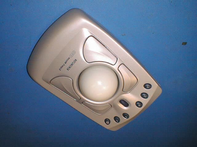
Click to zoom
Application Details
- Equipment Class
- DXX - Part 15 Low Power Communication Device Transmitter
- Date of Grant
- May 15, 2001
- Application Purpose
- Original Equipment
- Date of Application
- May 15, 2001
- Equipment Note
- Wireless Mouse
- Frequency Range
- 26.99500000 - 27.19500000
- Company
- ACCO Brands, Inc.
- Country
- United States
Documents & Files
Document Text
Text extracted from the exhibit documents filed with the FCC. Open a document above to read the original.
Users Manual
Turbo Mouse Pro Insert Copy Draft 1 2-16-01 SEH/ed bkm [FRONT] [Reversed Copy] READ THIS FIRST! Turbo Mouse Pro Wireless [Headline] Take a quick tour of the key features of your new Turbo Mouse Pro Wireless, the first wireless trackball for Mac® users. [Subhead1] Work freely without desktop clutter Position the Turbo Mouse® Pro Wireless where you want to use it and get personalized comfort plus wireless freedom. Non-line-of-sight radio frequency {RF) connection— similar to that used by cordless phones—lets you move your trackball off the desk and work anywhere within 6 feet of your computer. [Subhead2] Maximum performance, minimum effort. Your Turbo Mouse Pro Wireless lets you open applications or Web sites with the single touch of a DirectLaunch button. Using the enclosed MouseWorks software, you can program the four mouse buttons to perform repetitive tasks such as cutting, pasting, and opening and closing files. The integrated scroll wheel lets you speed through long documents or Web sites. Look inside to change the way you work. Connecting the Turbo Mouse® Pro Wireless receiver to your computer Once you connect the Radio Frequency (RF) receiver to your computer’s USB port, it can be placed anywhere on your desktop. The trackball will work anywhere within six feet of the receiver. Similar to a cordless telephone, the trackball operates on a radio frequency, so it does not need a clear line of sight between the receiver and the trackball. Connecting to a Macintosh computer: To connect to a Do this: USB port Plug the radio receiver’s cable into your computer’s USB port. [USB port illustration] You may also use the spare USB port on your keyboard or a USB port on a hub connected to your computer. You do not need to turn off your computer before connecting or disconnecting a USB device. [Subhead1] Ergonomically engineered for comfort. Your Turbo Mouse Pro Wireless is one of the most comfortable input devices available today. Its symmetrical design makes it simple to use with either hand, and wireless technology lets you place it anywhere. [Diagram Cutlines] 1. Place your hand over the top of the Turbo Mouse Pro Wireless, with the heel of your hand at its base. 2. Relax your wrist and fingers. Note where your fingers fall on the trackball, and which buttons are easiest to reach. 3. Follow the guidelines to program the DirectLaunch buttons and the four mouse buttons to handle repetitive tasks for you. [Subhead] Scroll faster. The integrated scroll wheel lets you page quickly through long documents or Web sites. Just roll the wheel with the tip of a finger for smooth, rapid scrolling. [Graphic of the six DirectLaunch buttons] [Subhead] DirectLaunch buttons let you access your favorite Web sites and applications with just one touch. The defining feature of your Turbo Mouse Pro Wireless is the row of six DirectLaunch buttons that gives you fingertip access to your favorite Web sites or applications. Never before has a trackball given you this power and convenience. DirectLaunch buttons are currently set to Mac Web sites we thought you’d find useful. Take a look for yourself! To program a DirectLaunch button to a Web site: 1. Open the Web site. 2. Press and hold one of the DirectLaunch buttons. 3. An alert will pop up to let you know the button has been programmed. 4. Repeat this process with the remaining DirectLaunch buttons. To program a DirectLaunch button to open an application: 1. Open the MouseWorks software and select the System-Wide Settings tab. 2. Select the Presets Tab. 3. Click on the pull-down menu for the button you want to program. Select Easy Launch. 4. Click Browse to select the application you want to launch from this button. 5. Click open. 6. Check the Label box and type the name you want to call this button. 7. Click OK, then close MouseWorks. That’s it! Now you have one-touch access to your six favorite Web sites or applications. A button programmed with a Web site will automatically launch your browser (if it’s not already running) and take you directly to that site. You can change your programmed choices as often as you like; just repeat the steps above. A button programmed with an application will open the application. [PAGE 4] [Graphic of the MouseWorks mouse button screen] [Subhead] One click handles repetitive tasks. The four programmable mouse buttons, when combined with the enclosed MouseWorks software, allow you to handle repetitive mouse tasks with a single click. Install the MouseWorks software on your computer, and program the four mouse buttons to automatically perform repetitive tasks (such as double-clicking, dragging, highlighting, cutting and pasting, etc.) for you. There is no “right” way to use the four mouse buttons – program the buttons that are easiest for you to reach to perform the tasks you use most often. You may want to experiment a bit with different options before deciding on the best way to personalize your Turbo Mouse Pro Wireless. FCC Statement NOTE: This equipment has been tested and found to comply with the limits for a Class B Digital Device, pursuant to Part 15 of the FCC rules. These limits are designed to provide reasonable protection against harmful interference in a residential situation. This equipment generates, uses, and radiates radio frequency energy, and if not installed and used in accordance with the instructions, may cause harmful interference to radio communications. However, there is no guarantee that interference will not occur in a particular installation. If this equipment does cause harmful interference to radio or television reception, which can be determined by turning the equipment off and on, the user is encouraged to try to correct the interference by one or more of the following measures: * Reorient or relocate the receiving antenna * Increase the separation between the equipment and the received * Connect the equipment to an AC outlet on a circuit different from the one the receiver is conne…
Text truncated - open the document above for the full version.
Block Diagram
Pacific Design Engineering Functional Specification - Monty Page 4 of 10 System Overview The input status of the trackball is monitored by a microcontroller on the Transmitter board. Whenever the microcontroller sees a change in the status, it sends a stream of data to the microcontroller on the Receiver board through an RF link. The receiver microcontroller will extract the information carried in the data stream and report to the PC by the PS2 or USB connection. There is a channel selection mechanism on both Transmitter and Receiver to avoid jamming by another user in the same frequency channel. The RF carrier is FSK modulated by a stream of Miller Code base band signal. Microcontroller Inputs - X-Y encoder, scroller, switches etc. Low battery shutdown Battery Low battery detect Freq. DoublerPower Amp Low Pass Filter Transmit Power control Modulation Channel Select Transimtter RF Receiver IF Microcontroller Demodulated data PS2/USB Channel Select RF IN DEMOD Receiver
Cover Letter(s)
Page 1 of 1 5/16/01 Barry C. Quinlan From:"Acme Testing" <[email protected]> To:"Certification Manager" <[email protected]> Sent:Thursday, April 05, 2001 12:32 PM Attach:bandwidth plot.doc Subject:Re: FCC ID: GV364240 Thank you for your quick review of this application. I have responded to the following questions below. Regards, Desiree Patterson ----- Original Message ----- From: Certification Manager To: Acme Testing Sent: Wednesday, April 04, 2001 5:34 AM Subject: FCC ID: GV364240 We have identified the following issues during our review of the application: 1. Please confirm that a new battery was used for the testing. Per 15.231 (e), a new battery was used during testing. 2. Please submit a bandwidth plot of the modulated signal so that we can confirm that the transmission remains within the band. A plot has been attached for your review. 3. The label uses wording from 15.19(b) rather than 15.19(a). The product is subject to certification and not DoC. Please supply modified label details. The client has been notified of the incorrect label and will modify. Once the modification is complete, I will forward new label diagrams for your review. Best regards Barry C. Quinlan Certification & Telecom Manager ------------------------------------------------------------------------------- Curtis-Straus LLC Voice: 978.486.8880 x270 527 Great Road Fax: 978.486.8828 Littleton, MA 01460 http://www.curtis-straus.com --------------------------------------------------------------------------------
ID Label/Location Info
PRINTERS LETTER Product/FCC Label - ExpertMouse RF Doc: 900-0527-00 To: TBD Document No: RS0527 From: Robert Shular Date: 2001/03/23 Product Name: ExpertMouse Pro - Wireless Model No(s): K64245 ACCO Canada, Kensington Technology Group Gravis Research & Development Centre, 2855 Campus Drive, #101-3750 North Fraser Way, San Mateo, California Burnaby, British Columbia USA 94403 Canada V5J 5E9 Item Description: Shipping Carton Retail Box/Gift Box Manual/Booklet Single Sheet Label Other: Component Part No: 900-0527-00 Paper Stock: Silver color mylar, permanent self-adhesive Flat Size: Finished Size: 75 mm x 38 mm Press: Cyan Magenta Yellow Black Pantone Color Chip(s): Finishing: UV Coating Aqueous Coating Other: Saddle Stitch Perfect Bind Fold: Other: Artwork and Proofing Materials Supplied: Negative Film Positive Film Line Screen: 150 Emulsion Up Emulsion Down Camera-ready Art Electronic Art Camera-ready Art is at % of actual size. Enlarge % for full size Cromalin proof Blueline proof Booklet mockup
Operational Description
Pacific Design Engineering Functional Specification - Monty Page 1 of 10 FUNCTIONAL SPECIFICATION FOR MONTY – KENSINGTON GRAVIS PREPARED BY: H.Y. LEUNG DATE: March 3, 2000 REVISION: 2 Pacific Design Engineering Functional Specification - Monty Page 2 of 10 Revision History Revision Description Date 1 First release to KGT December, 23, 1999 2 CRC2 includes battery status P March 3, 2000 Defined operands for CRC1, CRC2 Defined switches and battery status bits polarity Pacific Design Engineering Functional Specification - Monty Page 3 of 10 Introduction PDE was requested by Gravis to design a RF trackball code named Monty. PDE has generated this functional specification for PI Engineering as a tool to migrate their existing USB-PS2 firmware to accommodate the serial data stream from the receiver electronics. This functional specification will cover the following aspects: • An overview of the system • Communication Protocol • Electrical Signals • System Specifications • Appendix 1 – CRC Table Pacific Design Engineering Functional Specification - Monty Page 4 of 10 System Overview The input status of the trackball is monitored by a microcontroller on the Transmitter board. Whenever the microcontroller sees a change in the status, it sends a stream of data to the microcontroller on the Receiver board through an RF link. The receiver microcontroller will extract the information carried in the data stream and report to the PC by the PS2 or USB connection. There is a channel selection mechanism on both Transmitter and Receiver to avoid jamming by another user in the same frequency channel. The RF carrier is FSK modulated by a stream of Miller Code base band signal. Microcontroller Inputs - X-Y encoder, scroller, switches etc. Low battery shutdown Battery Low battery detect Freq. DoublerPower Amp Low Pass Filter Transmit Power control Modulation Channel Select Transimtter RF Receiver IF Microcontroller Demodulated data PS2/USB Channel Select RF IN DEMOD Receiver Pacific Design Engineering Functional Specification - Monty Page 5 of 10 Communication Protocol The Data Packet The transmitter remains in idle mode most of the time and transmits only if it sees a change in the trackball status. Before any packet is transmitted after the transmitter wakes up from the idle state, the Preamble and the Device ID are sent. The Preamble allows the receiver and detection circuitry to stabilize before the data packet is received. The Device ID identifies the transmitter to the receiver. After the Device ID, the Report Frames follow. The Report Frames will be sent as long as there is trackball status change. The IFI, Inter-Frame Idle, acts as a delimiter. It terminates a frame and separates it from the next one. If there is no transition received after any timer longer than two IFI, the receiver should assume the transmitter has returned to Idle mode. “Start of Frames”, SOF, are provided for the Device ID and Report Frame for transition synchronization as well as frame identification. Also, SOF for the Device ID helps to identify the product type. SOF for the Device ID is ‘01XX’ where XX is equal to ‘00’ for Monty. SOF for Report Frames are ‘0001’. However, the receiver firmware should recognize the SOF of the Report Frames as one of these patterns ‘0001’or ‘001’ with a leading IFI. The Device ID Bit # Length Description 0-3 4 Start of Frame Identifier b0b1b2b3 = 01XX where XX = 00 for Monty 4-7 4 4-bit ID The Device ID is sent once only after the Preamble. The Report Frame Each bit in the report Frame is defined as followings: Bit # Length Description 0-3 4 Start of Frame Identifier b0b1b2b3 = 0001 4-5 2 Frame Number – Identifies the frame being sent 6-16 11 State of Button 1 – 11, with ‘1’ represents closed of the switch 17-19 3 Z - Value of Vertical Scroll Axis, signed – DOWN scrolling is positive 20-26 7 Value of X – movement, signed – RIGHT is positive PREAMBLEIFIREPORT FRAMEIFIREPORT FRAMEIFI TX IDLE DATA PACKET DEVICE IDIFI Pacific Design Engineering Functional Specification - Monty Page 6 of 10 27-33 7 Value of Y – movement, signed – DOWN is positive 34 1 P - Transmitter Battery Status, with ‘1’ represents low battery condition 35-38 4 CRC1 including the frame #, buttons & Z 39-42 4 CRC2 including X , Y & P Total number of bits: 43 Symbol Period: 0.4ms Inter-Frame Idle time: 2.8ms The same trackball status can be sent up to 4 times. The receiver should ignore any report Frame with Frame number larger than zero if a valid report frame with smaller frame number was received. Bit Ordering The low significant bit is sent first and the most significant bit is sent last. Error Checking The validity of the packet is ensured by two 4-bit CRC checksums. The following describes the CRC checksum provided by KGT. The checksum is generated based on 16 bits of data with polynomial x 4 +x 2 +x 1 +1. In the KGT documents, “gripcrc.inc” & “crcgen.inc”, a table driven CRC algorithm which involve a 256-entry table (included in Appendix 1) are introduced: 1. Append ‘0’ to the LSB to make it a 16 bit data if data is less than 16 bits. 2. Look up the CRC table indexed by the MSB of the 16 bit data. 3. XOR the result with the LSB of the 16 bit data. 4. Look up the CRC table indexed by the result in step 3. 5. The higher 4 bits is taken as the CRC for the 16-bit data. There is no error recovery scheme provided. The receiver should drop any error packet and keep looking for the good packets. SOF F R A M E # BUTTONS 1-11 ZXYPCRC1CRC2 REPORT FRAME FORMAT Pacific Design Engineering Functional Specification - Monty Page 7 of 10 Operands for CRC1 and CRC2 Evaluation Operands for CRC1 is defined below: b7 b6 b5 b4 b3 b2 b1 b0 Higher Order sw6 sw5 sw4 sw3 sw2 sw1 fm1 fm0 Lower Order z2 z1 z0 sw11 sw10 sw9 sw8 sw7 Operands for CRC2 is defined below: b7 b6 b5 b4 b3 b2 b1 b0 Higher Order y0 x6 x5 x4 x3 x2 x 1 x0 Lower Order 0 P y6 y5 y4 y3 y2 y1 Where: fm0,fm1 are bits for Frame Number. sw1 to sw11 are switch status. x0 to x6 are x-axis of…
Text truncated - open the document above for the full version.
Test Report
DATE OF ISSUANCE: 28 March 2001 REPORT NUMBER: 2001062 FCC ID: GV364240 PAGE 1 OF 14 Partial reproduction of this document is prohibited without prior written consent of Acme Testing Inc. ACME TESTING INC., 2002 VALLEY HWY, P.O. BOX 3, ACME, WASHINGTON 98220-0003 888-226-3837. REPORT OF MEASUREMENTS PART 15C - INTENTIONAL RADIATOR DEVICE: WIRELESS MOUSE MODEL: 64240 (TURBO MOUSE PRO WIRELESS) MANUFACTURER: KENSINGTON TECHNOLOGY GROUP A DIVISION OF ACCO BRANDS, INC. ADDRESS: 2855 CAMPUS DRIVE SAN MATEO, CA USA 94403 THE DATA CONTAINED IN THIS REPORT WAS COLLECTED ON DECEMBER 19 2000 AND COMPILED BY: PAUL G. SLAVENS CHIEF EMC ENGINEER DATE OF ISSUANCE: 28 March 2001 REPORT NUMBER: 2001062 FCC ID: GV364240 PAGE 2 OF 14 WORK ORDER: 9092hr 1. GENERAL.............................................................................................................................................................3 1.1 PURPOSE...........................................................................................................................................................3 1.2 MANUFACTURER CONTACT INFORMATION..........................................................................................................3 1.3 TEST LOCATION.................................................................................................................................................3 1.4 TEST PERSONNEL..............................................................................................................................................3 2. TEST RESULTS SUMMARY...............................................................................................................................4 3. DESCRIPTION OF EQUIPMENT AND PERIPHERALS..................................................................................5 3.1 EQUIPMENT UNDER TEST (EUT)........................................................................................................................5 3.2 EUT PERIPHERALS............................................................................................................................................5 3.3 DESCRIPTION OF INTERFACE CABLES..................................................................................................................6 3.4 MODE OF OPERATION DURING TESTS.................................................................................................................6 3.5 MODIFICATIONS REQUIRED FOR COMPLIANCE.....................................................................................................6 4. ANTENNA REQUIREMENT...............................................................................................................................7 4.1 REGULATION.....................................................................................................................................................7 4.2 RESULT.............................................................................................................................................................7 5. CONDUCTED EMISSIONS TESTS.....................................................................................................................8 5.1 TEST EQUIPMENT..............................................................................................................................................8 5.2 PURPOSE...........................................................................................................................................................8 5.3 TEST PROCEDURES............................................................................................................................................8 5.4 TEST RESULTS...................................................................................................................................................9 6. RADIATED EMISSIONS TESTS.......................................................................................................................10 6.1 REGULATION...................................................................................................................................................10 6.2 TEST EQUIPMENT............................................................................................................................................10 6.3 TEST PROCEDURES..........................................................................................................................................11 6.4 TEST RESULTS.................................................................................................................................................12 7. TEST SETUP PHOTOGRAPHS........................................................................................................................13 8. MISCELLANEOUS COMMENTS AND NOTES..............................................................................................14 DATE OF ISSUANCE: 28 March 2001 REPORT NUMBER: 2001062 FCC ID: GV364240 PAGE 3 OF 14 1. General 1.1 Purpose The purpose of this report is to show compliance to the FCC regulations for unlicensed devices operating under section 15.227 of the Code of Federal Regulations title 47. 1.2 Manufacturer Contact Information Company Name: ACCO Canada, Gravis Research & Development Centre Contact: Robert Shular Street Address: #101-3750 North Fraser Way City/State/Zip: Burnaby, British Columbia, Canada, V5J 5E9 Telephone: 1-604-431-5020 extension 1065 E-mail: [email protected] Web: www.kensington.com 1.3 Test location Company: Acme Testing Inc. Street Address: 2002 Valley Highway Mailing Address: PO Box 3 City/State/Zip: Acme WA 98220-0003 Laboratory: Test Site 2 Telephone: 888 226-3837 Fax: 360 595-2722 E-mail: [email protected] Web: www.acmetesting.com 1.4 Test Personnel Paul G. Slavens, Chief EMC Engineer DATE OF ISSUANCE: 28 March 2001 REPORT NUMBER: 2001062 FCC ID: GV364240 PAGE 4 OF 14 2. Test Results Summary Summary of Test Res…
Text truncated - open the document above for the full version.
Test Setup Photos
DATE OF ISSUANCE: 28 March 2001 REPORT NUMBER: 2001062 FCC ID: GV364240 PAGE 13 OF 14 7. Test Setup Photographs
Contact Information
Applicant
Benjamin Hsu(Compliance Manager)
Test Firm
Acme Testing Co.Harry Hodes
Technical Specifications
| # | Rule Parts | Frequency Range | Power Output |
|---|---|---|---|
| 1 | 15C | 26.995 MHz - 27.195 MHz | - |
Other Applications from ACCO Brands, Inc.
GV3M01709-K
Nov 28, 2024KB270 EQ Rechargeable Keyboard
Equipment Class
DTS - Digital Transmission SystemGV3M01500-MA
Jan 28, 2024Kensington Vertical Wireless Mouse
Equipment Class
DSS - Part 15 Spread Spectrum Transmitter
GV3M01687-M
Sep 17, 2023MY430 Rechargeable Mouse
Equipment Class
DTS - Digital Transmission System
GV3M01702-P
Sep 17, 2023Wireless Presenter with Red Laser-Nano Receiver
Equipment Class
DSS - Part 15 Spread Spectrum Transmitter
GV3M01440-KB
Aug 24, 2023Pro Fit Ergo Wireless Keyboard
Equipment Class
DSS - Part 15 Spread Spectrum Transmitter