GV372225PilotMouse Bluetooth
ACCO Brands, Inc.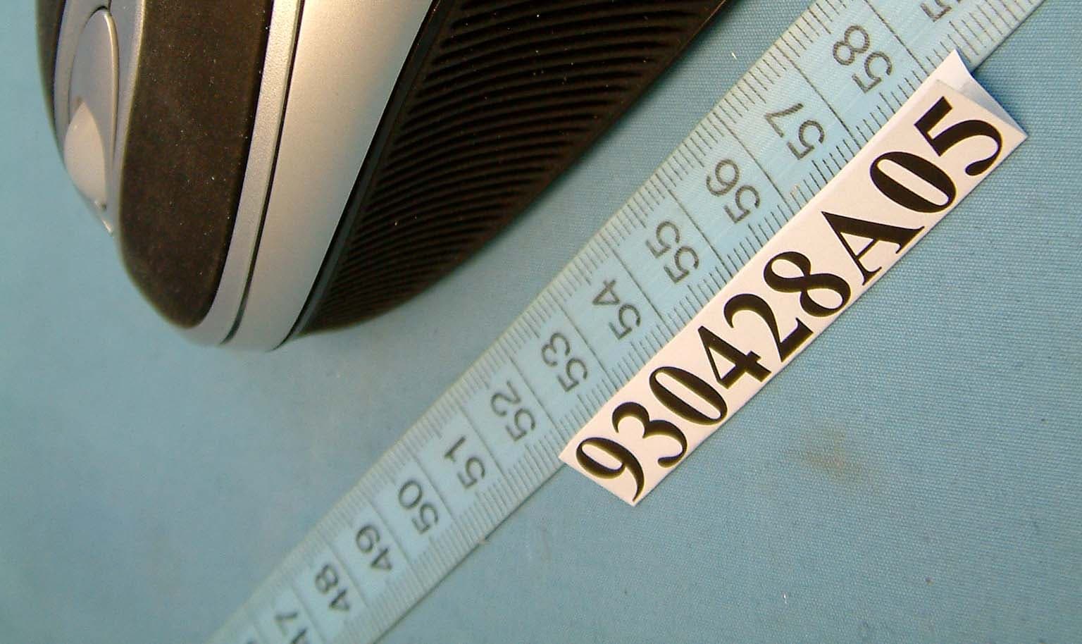
Click to zoom
Application Details
- Equipment Class
- DTS - Digital Transmission System
- Date of Grant
- Jul 06, 2004
- Application Purpose
- Original Equipment
- Date of Application
- Jul 06, 2004
- Equipment Note
- PilotMouse Bluetooth
- Frequency Range
- 2402.00000000 - 2480.00000000
- Company
- ACCO Brands, Inc.
- Country
- United States
Documents & Files
Document Text
Text extracted from the exhibit documents filed with the FCC. Open a document above to read the original.
Users Manual
PilotMouse Bluetooth ® User Manual PilotMouse Bluetooth®• 1 Contacting Kensington Troubleshooting information and answers to frequently asked questions are available 24 hours a day on the Kensington Web site at www.support.kensington.com. Support by Telephone Technical Support is available by telephone. Please visitwww.kensington.comfor hours. U.S. and Canada 800-535-4242 or 650-572-2700 Fax 650-358-0152 Mexico 52(55)5384-0620 20 • PilotMouse Bluetooth® This manual is copyright © 2004 Kensington Technology Group, a division of ACCO Brands, Inc. Any unauthorized copying, duplicating, or other reproduction of the contents hereof is prohibited without written consent from Kensington Technology Group. All rights reserved. 04/04 Kensington and MouseWorks are registered trademarks of ACCO World Corporation. The Bluetooth word mark and logos are owned by the Bluetooth SIG, Inc., and any use of such marks by Kensington is under license. Mac and Macintosh are registered trademarks of Apple Computer Inc. All other registered and unregistered trademarks are the sole property of their respective owners. 901-0579-00 Kensington Technology Group 2000 Alameda de las Pulgas Second Floor San Mateo, CA 94403 USA www.kensington.com ACCO Europe PLC Gatehouse Road Aylesbury Bucks HP19 8DT UNITED KINGDOM ACCO Canada Inc. 5 Precidio Court Brampton, Ontario L6S 6B7 CANADA 72225_PiMBluetooth_Print 4/22/04 12:38 PM Page 20 Index Contents . . . . . . . . . . . . . . . . . . . . . . . . . . . . . . . . . page 3 Compatibility and System Requirements . . page 3 Battery Installation . . . . . . . . . . . . . . . . . . . . . . . page 4 Windows Pairing and Connecting . . . . . . . . . . . . . . . . . . page 5–6 Activating Discover Mode . . . . . . . . . . . . . . . page 7 Troubleshooting . . . . . . . . . . . . . . . . . . . . . . . . page 10–11 MacintoshR Pairing and connecting . . . . . . . . . . . . . . . . . . page 12–14 Troubleshooting . . . . . . . . . . . . . . . . . . . . . . . . page 15 MouseWorksR for MacR . . . . . . . . . . . . . . . . . . page 16 Technical Support . . . . . . . . . . . . . . . . . . . . . . . page 17 Warranty Information . . . . . . . . . . . . . . . . . . . . page 18–19 Federal Communications Commission Radio Frequency Interference Statement Note: The Kensington PilotMouse Bluetooth® model no. 72225 has been tested and found to comply with the limits for a Class B digital device, pursuant to Part 15 of the FCC Rules. These limits are designed to provide reasonable protection against harmful interference in a residential installation. This equipment generates, uses and can radiate radio frequency energy and, if not installed and used in accordance with the instructions, may cause harmful interference to radio communications. However, there is no guarantee that interference will not occur in a particular installation. If this equipment does cause harmful interference to radio or television reception, which can be determined by turning the equipment off and on, the user is encouraged to try to correct the interference by one of the following measures: -Reorient or relocate the receiving antenna. -Increase the separation between the equipment and receiver. -Connect the equipment into an outlet on a circuit different from that to which the receiver is connected. -Consult the dealer or an experienced radio/TV technician for help. FCC Caution: Any changes or modifications not expressly approved by the party responsible for compliance could void the user's authority to operate this equipment. . Declaration of Conformity Compliance Statement for the Kensington PilotMouse Bluetooth® The Kensington PilotMouse BluetoothR model no. 72225 complies with Part 15 of the FCC Rules. Operation is subject to two conditions: (1) This device may not cause harmful interference, and, (2) this device must accept any interference received, including interference that may cause undesired operation. As defined in Section 2.909 of the FCC Rules, the responsible party for this device is Kensington Technology Group, 2000 Alameda de las Pulgas, Second Floor, San Mateo, CA 94403, USA, (650) 572-2700. PilotMouse BluetoothR • 19 2 PilotMouse BluetoothR • Contents • PilotMouse Bluetooth® • 2 AA batteries • Manual Compatibility and System Requirements Windows®XP with Bluetooth®enabling software that includes support for mice and keyboards. Mac OS X (10.2.8 or later) running Bluetooth ®software version 1.5 or later. PilotMouse Bluetooth®is designed to work with Bluetooth®enabled Macintosh and PC computers. Bluetooth®is generally enabled through either built-in Bluetooth®hardware, a Bluetooth®USB adapter, or other type of Bluetooth®adapter. PilotMouse Bluetooth®• 3 1-Year Warranty KENSINGTON TECHNOLOGY GROUP (“KENSINGTON”) warrants this PRODUCT against defects in material and workmanship under normal use and service for one year from the original date of purchase. KENSINGTON, at its option, shall repair or replace the defective unit covered by this warranty. Please retain the dated sales receipt as evidence of the date of purchase. You will need it for any warranty service. In order to keep this warranty in effect, the product must have been handled and used as prescribed in the instructions accompanying this warranty. This warranty does not cover any damage due to accident, misuse, abuse, or negligence. This warranty is valid only if the product is used on the computer or system specified on the product box. Please check product box for details or call technical support. Repair or replacement, as provided under this warranty, is your exclusive remedy. KENSINGTON shall not be liable for any incidental or consequential damages. Implied warranties of merchantability and fitness for a particular purpose on this product are limited in duration to the duration of this warranty. Some states/countries do not allow the exclusion or limitation of incidental or consequential damages, so the above limitation or exclusion may not apply to yo…
Text truncated - open the document above for the full version.
Cover Letter(s)
FEDERAL COMMUNICATIONS COMMISSION DECLARATION OF CONFORMITY (DoC) FOR THE FOLLOWING EQUIPMENT: PRODUCT NAME: PilotMouse Bluetooth MODEL NO.: 72225 TRADE NAME: Kensington, Primax, ACCO IS HEREWITH CONFIRMED AND FOUND TO COMPLY WITH THE REQUIREMENTS OF CFR 47 PART 15 REGULATION. THE RESULTS OF ELECTROMAGNETIC EMISSION EVALUATION ARE SHOWN IN THE REPORT NO.: D930428A05 THIS DEVICE COMPLIES WITH PART 15 OF THE FCC RULES. OPERATION IS SUBJECT TO THE FOLLOWING TWO CONDITIONS: (1) THIS DEVICE MAY NOT CAUSE HARMFUL INTERFERENCE AND, (2) THIS DEVICE MUST ACCEPT ANY INTERFERENCE RECEIVED, INCLUDING INTERFERENCE THAT MAY CAUSE UNDESIRED OPERATION. THE FOLLOWING LOCAL MANUFACTURER/IMPORTER IS RESPONSIBLE FOR THIS DECLARATION ACCO BRANDS, INC. (COMPANY NAME) 2000 Alameda de las Pulgas, 2nd Floor, San Mateo, CA 94403-1289 USA (COMPANY ADDRESS) TEL +1 604 431-5020 ext.1022 FAX+1 (604) 431 5155 Raymon Hung Product Development Manager/ Electrical Engineer (NAME) (TITLE) 2004/06/15 (SIGNATURE) (DATE)
Cover Letter(s)
Power of Attorney To whom it may concern: We, the undersigned ACCO Brands, Inc. hereby authorize Advance Data Technology Corporation (ADT) of Taiwan to act on our behalf in all matters relating to all processes required in the FCC Part 15C approval and any communication needed with the national authority. Any and all acts carried out by ADT on our behalf shall have the same effects as acts of our own. If you have any questions regarding the authorization, please don’t hesitate to contact us. Thank you! Sincerely yours, ------------------------------------------------------------------- Raymon Hung Product Development Manager/ Electrical Engineer Phone: +1 604 431-5020 ext.1022 Fax: +1 (604) 431 5155 Email: [email protected]
Cover Letter(s)
Federal Communications Commission Authorization and Evaluation Division Confidentiality Request FCC ID: GV372225 Pursuant to Sections 0.457 and 0.459 of the Commission’s Rules, the Applicant hereby requests confidential treatment of information accompanying this Application as outlined below: Schematics Block Diagram The above materials contain trade secrets and proprietary information not customarily released to the public. The public disclosure of these matters might be harmful to the Applicant and provide unjustified benefits to its competitors. The Applicant understands that pursuant to Rule 0.457, disclosure of this Application and all accompanying documentation will not be made before the date of the Grant for this application. Sincerely yours, ------------------------------------------------------------------- Raymon Hung Product Development Manager/ Electrical Engineer Phone: +1 604 431-5020 ext.1022 Fax: +1 (604) 431 5155 Email: [email protected]
External Photos
(Photo 1) FCC ID: GV372225 (Photo 2) FCC ID: GV372225
ID Label/Location Info
(Fig. 1) FCC ID: GV372225 FCC LABEL LOCATION The label will be permanently affixed at a conspicuous location on the device. Label
ID Label/Location Info
PilotMouse Bluetooth Wireless Model#72225 Serial No. AYYWWXXXXXX Kensington Technology Group, a division of ACCO Brands,inc. www.kensington.com U.S. 800-535-4242 Made in China 900-1024-00
Internal Photos
(Photo 3) FCC ID: GV372225 (Photo 4) FCC ID: GV372225 (Photo 5) FCC ID: GV372225 (Photo 6) FCC ID: GV372225 (Photo 7) FCC ID: GV372225 (Photo 8) FCC ID: GV372225 (Photo 9) FCC ID: GV372225 (Photo 10) FCC ID: GV372225 (Photo 11) FCC ID: GV372225 (Photo 12) FCC ID: GV372225 (Photo 13) FCC ID: GV372225
Operational Description
FCC ID: GV372225 Report No.: RF930428A05 Operational Description This device is a Frequency Hopping device with 79 hopping frequencies. The antenna type is Micro String antenna and there is no antenna connector used. The EUT is a unit that contains a Bluetooth radio module. Bluetooth is a short-range wireless technology operating in the 2.4 GHz band. It enables devices to have the ability to form networks and exchange information. The other instruction, please have a look at the users manual.
Test Report
FCC ID: GV372225 Report No.: RF930428A051Issued: June 16, 2004 FCC TEST REPORT REPORT NO.: RF930428A05 MODEL NO.: 72225 RECEIVED: April 28, 2004 TESTED: May 20 ~ June 9, 2004 APPLICANT: ACCO Brands, Inc. ADDRESS: 2855 Campus Drive San Mateo, CA 94403 United States ISSUED BY: Advance Data Technology Corporation LAB LOCATION: 47 14th Lin, Chiapau Tsun, Linko, Taipei, Taiwan, R.O.C. This test report consists of 58 pages in total. It may be duplicated completely for legal use with the approval of the applicant. It should not be reproduced except in full, without the written approval of our laboratory. The client should not use it to claim product endorsement by CNLA or any government agencies. The test results in the report only apply to the tested sample. 0528 ILAC MRA FCC ID: GV372225 Report No.: RF930428A052Issued: June 16, 2004 TABLE OF CONTENTS 1CERTIFICATION .........................................................................................................................4 2SUMMARY OF TEST RESULTS.................................................................................................5 3GENERAL INFORMATION .........................................................................................................6 3.1GENERAL DESCRIPTION OF EUT............................................................................................6 3.2DESCRIPTION OF TEST MODES..............................................................................................7 3.3GENERAL DESCRIPTION OF APPLIED STANDARDS.............................................................7 3.4DESCRIPTION OF SUPPORT UNITS........................................................................................8 3.5CONFIGURATION OF SYSTEM UNDER TEST ........................................................................8 4TEST PROCEDURES AND RESULTS .......................................................................................9 4.1CONDUCTED EMISSION MEASUREMENT..............................................................................9 4.2number of hopping frequency used.............................................................................................9 4.2.1LIMIT OF HOPPING FREQUENCY USED .................................................................................9 4.2.2TEST INSTRUMENTS ................................................................................................................9 4.2.3TEST PROCEDURES ...............................................................................................................10 4.2.4DEVIATION FROM TEST STANDARD .....................................................................................10 4.2.5TEST SETUP ............................................................................................................................11 4.2.6TEST RESULTS ........................................................................................................................11 4.3DWELL TIME ON EACH CHANNEL .........................................................................................14 4.3.1LIMIT OF DWELL TIME USED .................................................................................................14 4.3.2TEST INSTRUMENTS ..............................................................................................................14 4.3.3TEST PROCEDURES ...............................................................................................................15 4.3.4DEVIATION FROM TEST STANDARD .....................................................................................15 4.3.5TEST SETUP ............................................................................................................................15 4.3.6TEST RESULTS ........................................................................................................................16 4.4CHANNEL BANDWIDTH...........................................................................................................23 4.4.1LIMITS OF CHANNEL BANDWIDTH ........................................................................................23 4.4.2TEST INSTRUMENTS ..............................................................................................................23 4.4.3TEST PROCEDURE .................................................................................................................24 4.4.4DEVIATION FROM TEST STANDARD .....................................................................................24 4.4.5TEST SETUP ............................................................................................................................24 4.4.6EUT OPERATING CONDITION ................................................................................................24 4.4.7TEST RESULTS ........................................................................................................................25 4.5HOPPING CHANNEL SEPARATION ........................................................................................29 4.5.1LIMIT OF HOPPING CHANNEL SEPARATION........................................................................29 4.5.2TEST INSTRUMENTS ..............................................................................................................29 FCC ID: GV372225 Report No.: RF930428A053Issued: June 16, 2004 4.5.3TEST PROCEDURES ...............................................................................................................30 4.5.4DEVIATION FROM TEST STANDARD .....................................................................................30 4.5.5TEST SETUP ............................................................................................................................30 4.5.6TEST RESULTS ........................................................................................................................31 4.6MAXIMUM PEAK OUTPUT POWER –using POWER METTE…
Text truncated - open the document above for the full version.
Test Report
FCC ID: GV372225 Report No.: RF930428A0531Issued: June 16, 2004 4.5.6 TEST RESULTS Channel Frequency (MHz) Adjacent Channel Separation Minimum Limit (kHz) Pass / Fail 024021.005 MHz1000PASS 3924411.000 MHz1000PASS 7824801.005 MHz1000PASS The minimum limit is 20dB bandwidth. Test results please refer to next three pages. FCC ID: GV372225 Report No.: RF930428A0532Issued: June 16, 2004 Channel 0 FCC ID: GV372225 Report No.: RF930428A0533Issued: June 16, 2004 Channel 39 FCC ID: GV372225 Report No.: RF930428A0534Issued: June 16, 2004 Channel 78 FCC ID: GV372225 Report No.: RF930428A0535Issued: June 16, 2004 4.6 MAXIMUM PEAK OUTPUT POWER –USING POWER METTER 4.6.1 LIMITS OF MAXIMUM PEAK OUTPUT POWER MEASUREMENT The Maximum Peak Output Power Measurement is 30dBm. 4.6.2 INSTRUMENTS Description & ManufacturerModel No.Serial No.Calibrated Until SIGNAL GENERATOR / AgilentE8257CMY43320668Dec. 31, 2004 NOTE: The calibration interval of the above test instruments is 12 months and the calibrations are traceable to NML/ROC and NIST/USA. FCC ID: GV372225 Report No.: RF930428A0536Issued: June 16, 2004 4.6.3 TEST PROCEDURES 1. Check the calibration of the measuring instrument using either an internal calibrator or a known signal from an external generator. 2. Turn on the EUT and connect it to measurement instrument. Then set it to any one convenient frequency within its operating range. Set a reference level on the measuring instrument equal to the highest peak value. 3. The center frequency of the spectrum analyzer is set to the fundamental frequency and using 3 MHz RBW and 3 MHz VBW. 4. Measure the frequency difference of two frequencies that were attenuated 20dB from the reference level. Record the frequency difference as the emission bandwidth. 5. Repeat above procedures until all frequencies measured were complete. 4.6.4 DEVIATION FROM TEST STANDARD No deviation FCC ID: GV372225 Report No.: RF930428A0537Issued: June 16, 2004 4.6.5 TEST SETUP For the actual test configuration, please refer to the related Item – Photographs of the Test Configuration. 4.6.6 EUT OPERATING CONDITION The software provided by client enabled the EUT to transmit and receive data at lowest, middle and highest channel frequencies individually. EUTPOWER METER FCC ID: GV372225 Report No.: RF930428A0538Issued: June 16, 2004 4.6.7 TEST RESULTS Output Power to Antenna: CHANNEL CHANNEL FREQUENCY (MHz) PEAK POWER OUTPUT (dBm) PEAK POWER LIMIT (dBm) PASS/FAIL 024023.3030PASS 3924413.4630PASS 7824802.7730PASS FCC ID: GV372225 Report No.: RF930428A0539Issued: June 16, 2004 Channel 0 FCC ID: GV372225 Report No.: RF930428A0540Issued: June 16, 2004 Channel 39 FCC ID: GV372225 Report No.: RF930428A0541Issued: June 16, 2004 Channel 78 FCC ID: GV372225 Report No.: RF930428A0542Issued: June 16, 2004 4.7 RADIATED EMISSION MEASUREMENT 4.7.1 LIMITS OF RADIATED EMISSION MEASUREMENT Emissions radiated outside of the specified bands, shall be according to the general radiated limits in 15.209 as following: Frequencies (MHz) Field strength (microvolts/meter) Measurement distance (meters) 0.009-0.4902400/F(kHz)300 0.490-1.70524000/F(kHz)30 1.705-30.03030 30-881003 88-2161503 216-9602003 Above 9605003 As shown in 15.35(b), for frequencies above 1000MHz, the field strength limits are based on average detector, however, the peak field strength of any emission shall not exceed the maximum permitted average limits, specified above by more than 20dB under any condition of modulation. FCC ID: GV372225 Report No.: RF930428A0543Issued: June 16, 2004 4.7.2 TEST INSTRUMENTS DESCRIPTION & MANUFACTURER MODEL NO.SERIAL NO. CALIBRATED UNTIL HP Spectrum Analyzer8590L3544A01176May. 31, 2005 HP Preamplifier8447D2944A08485Apr. 26, 2005 * HP Preamplifier8449B3008A01924Oct. 12, 2004 * HP Preamplifier8449B3008A01638Oct. 17, 2004 SCHAFFNER TEST RECEIVER SCR 3501408Jan. 8, 2005 * ROHDE & SCHWARZ TEST RECEIVER ESMI 839013/007 839379/002 Feb. 12, 2005 SCHWARZBECK Tunable Dipole Antenna SCHWARZBECK Tunable Dipole Antenna VHA 9103 UHA 9105 NA 977 Nov. 15, 2004 * CHASE BILOG AntennaCBL6112A2221July 26, 2004 * EMCO Horn Antenna31156714Nov. 26, 2004 * EMCO Horn Antenna31159312-4192Feb. 28, 2005 * EMCO Turn Table10601115NA * CHANCE TowerCM-AT40CM-A010NA * Software ADT_Radiate d_V5.14 NANA * ANRITSU RF SwitchesMP59BM35046Dec. 11, 2004 * TIMES RF cableLMR-600CABLE-ST5-01Dec. 11, 2004 NOTE:1. The calibration interval of the above test instruments is 12 months. And the calibrations are traceable to NML/ROC and NIST/USA. 2. “*” = These equipment are used for the final measurement. 3. The horn antenna and HP preamplifier (model: 8449B) are used only for the measurement of emission frequency above 1GHz if tested. 4. The test was performed in ADT Open Site No. 5. 5. The VCCI Site Registration No. R-1039. FCC ID: GV372225 Report No.: RF930428A0544Issued: June 16, 2004 4.7.3 TEST PROCEDURES a. The EUT was placed on the top of a rotating table 0.8 meters above the ground at a 10 meter open area test site. The table was rotated 360 degrees to determine the position of the highest radiation. b. The EUT was set 3 meters away from the interference-receiving antenna, which was mounted on the top of a variable-height antenna tower. c. The antenna is a broadband antenna, and its height is varied from one meter to four meters above the ground to determine the maximum value of the field strength. Both horizontal and vertical polarizations of the antenna are set to make the measurement. d. For each suspected emission, the EUT was arranged to its worst case and then the antenna was tuned to heights from 1 meter to 4 meters and the rotatable table was turned from 0 degrees to 360 degrees to find the maximum reading. e. The test-receiver system was set to Peak Detect Function and Specified Bandwidth with Maximum Hold Mode. f. If the emission level of the EUT in peak mode was 10 dB lower than the limit specified, then testing could be stopped and the peak values of the EUT would be reported. Otherwise the emis…
Text truncated - open the document above for the full version.
Test Setup Photos
FCC ID: GV372225 Report No.: RF930428A0557Issued: June 16, 2004 5 PHOTOGRAPHS OF THE TEST CONFIGURATION RADIATED EMISSION TEST
Contact Information
Applicant
Benjamin Hsu(Compliance Manager)
Technical Contact
Advance Data Technology CorporationEllis Wu
[email protected]+88633183232
No.19 Hwa Ya 2nd rd. · Kueishan Taoyuan · Taiwan
Test Firm
Bureau Veritas CPS (H.K.) Ltd. Taoyuan BranchRichard Chen
Technical Specifications
| # | Rule Parts | Frequency Range | Power Output |
|---|---|---|---|
| 1 | 15C | 2.40 GHz - 2.48 GHz | 2.20 mW |
Other Applications from ACCO Brands, Inc.
GV3M01709-K
Nov 28, 2024KB270 EQ Rechargeable Keyboard
Equipment Class
DTS - Digital Transmission SystemGV3M01500-MA
Jan 28, 2024Kensington Vertical Wireless Mouse
Equipment Class
DSS - Part 15 Spread Spectrum Transmitter
GV3M01687-M
Sep 17, 2023MY430 Rechargeable Mouse
Equipment Class
DTS - Digital Transmission System
GV3M01702-P
Sep 17, 2023Wireless Presenter with Red Laser-Nano Receiver
Equipment Class
DSS - Part 15 Spread Spectrum Transmitter
GV3M01440-KB
Aug 24, 2023Pro Fit Ergo Wireless Keyboard
Equipment Class
DSS - Part 15 Spread Spectrum Transmitter