GV372242PilotMouse Laser Wireless
ACCO Brands, Inc.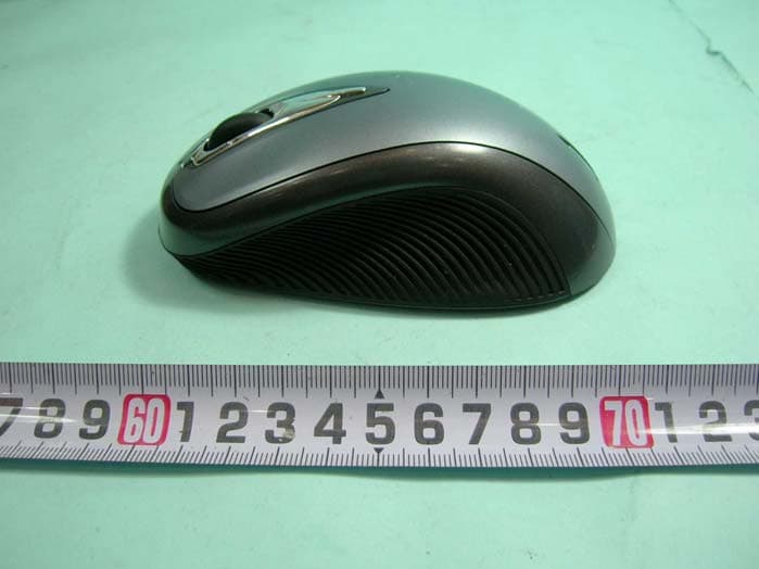
Click to zoom
Application Details
- Equipment Class
- DXX - Part 15 Low Power Communication Device Transmitter
- Date of Grant
- Feb 15, 2006
- Application Purpose
- Original Equipment
- Date of Application
- Feb 15, 2006
- Equipment Note
- PilotMouse Laser Wireless
- Frequency Range
- 2402.00000000 - 2470.00000000
- Company
- ACCO Brands, Inc.
- Country
- United States
Documents & Files
Document Text
Text extracted from the exhibit documents filed with the FCC. Open a document above to read the original.
Users Manual
PilotMouse Laser Wireless User Manual Index Battery Installation . . . . . . . . . . . . . . . . . . . . . . .page 2 Wireless Installation . . . . . . . . . . . . . . . . . . . . . .page 3–4 Common Troubleshooting Steps . . . . . . . . . .page 5 Optional Battery Saving Feature . . . . . . . . . .page 6 Comfort Guidelines . . . . . . . . . . . . . . . . . . . . . .page 7 Technical Support . . . . . . . . . . . . . . . . . . . . . . . .page 8 Warranty Information . . . . . . . . . . . . . . . . . . . .page 9–11 PilotMouse Laser Wireless • 1 72242_B.qxd 7/28/05 5:37 PM Page 1 Wireless Installation To Establish a Wireless Connection: After placing batteries in the mouse, make sure that the slide switch (3) on the underside of the mouse is in the “on” position. Plug the USB Wireless Receiver into a USB port on your computer. Your mouse should now be ready to use. Re-establishing a Wireless Connection: If the connection between your mouse and receiver is broken (mouse is in proper working order working with good batteries, and the receiver is installed properly, yet it is not working), or if you are experiencing interference (often detected by erratic or halted cursor movement), you may need to re-establish a wireless connection. Battery Installation Please be sure the batteries are installed properly in the mouse. The proper orientation for the batteries is indicated in the battery compartment for each device. Average battery life for your wireless mouse is 2-3 months, depending on usage. The wireless receiver indicator light will turn red when your batteries are low. 2 • PilotMouse Laser Wireless PilotMouse Laser Wireless • 3 1 3 2 72242_B.qxd 7/28/05 5:37 PM Page 2 Common Troubleshooting Steps 1. Unplug and re-plug the receiver. Repeat steps listed on pages 3 & 4 to re-establish a wireless connection 2. Install a fresh set of batteries in the mouse 3. Test the device on another USB port or computer. 4. Some surfaces may “trick”the laser sensor, such as reflective surfaces like glass or mirrors. The laser sensor should perform well on all other surfaces. 5. If you would like to program buttons, have advanced acceleration control or set a rest reminder, please visitwww.software.kensington.comto download the latest MouseWorks software. Be sure to install the correct version for your mouse. 6. To establish a wireless connection, see instructions on pages 3 & 4. 7. To save battery power, turn off the mouse when not in use. See instructions on page 6. To Re-establish a Wireless Connection: With the USB receiver in position and mouse turned on, press the “connect” button on the receiver (1), and within 10 seconds, also press the “connect”button on the bottom of the mouse (2). You have now established a new connection for the mouse. If this does not work, try repeating these steps while holding the mouse close to the receiver. This step may need to be repeated 2–3 times for the mouse to synchronize. If necessary, repeat this procedure after replacing depleted batteries. IMPORTANT: This wireless device is similar to an FM radio, the position of your computer and surrounding objects (especially metal objects) may effect your wireless reception and range (average range is approximately 10 meters or 30 feet). NOTE: Unlike older optical mice, a laser mouse does not emit visible light. Your new mouse will operate correctly even if you do not see a light. Installing Kensington MouseWorks ® software To access full functionality for your new mouse install Kensington MouseWorks®software. The install is optional; your mouse will function without installing the software. 4 • PilotMouse Laser Wireless PilotMouse Laser Wireless • 5 72242_B.qxd 7/28/05 5:37 PM Page 4 Comfort Guidelines Please visit HealthyComputing.com for helpful comfort tips when using this device. Important: Computer User Health Information In recent years, medical attention on occupational injuries has identified normal, seemingly harmless activities as a potential cause of a wide range of problems collectively known as Repetitive Stress Injuries (RSI) or Cumulative Trauma Disorders (CTD). It is now recognized that any repetitive motion may contribute to these health problems. As a computer user, you might also be at risk. By paying attention to the way you perform your work, use your computer and phone, play sports, and work around the house, you can identify the behaviors that may be putting you at risk. If you experience pain, swelling, numbness, or weakness in your wrists or hands (especially during sleep), see your physician immediately. For helpful information, visit www.HealthyComputing.comor a reputable book. Optional Battery Saving Feature To preserve battery life when not using the mouse for long periods of time, slide the switch (3) to off. 6 • PilotMouse Laser Wireless PilotMouse Laser Wireless • 7 3 72242_B.qxd 7/28/05 5:37 PM Page 6 5-Year Warranty KENSINGTON TECHNOLOGY GROUP (“KENSINGTON”) warrants this Kensington PilotMouse Laser Wireless against defects in material and workmanship under normal use and service for five years from the original date of purchase. KENSINGTON, at its option, shall repair or replace the defective unit covered by this warranty. Please retain the dated sales receipt as evidence of the date of purchase. You will need it for any warranty service. In order to keep this warranty in effect, the product must have been handled and used as prescribed in the instructions accompanying this warranty. This warranty does not cover any damage due to accident, misuse, abuse, or negli- gence. This warranty is valid only if the product is used on the computer or system specified on the product box. Please check product box for details or call technical support. Repair or replacement, as provided under this warranty, is your exclusive remedy. KENSINGTON shall not be liable for any incidental or consequential damages. Implied warranties of merchantability and fitness for a particular purpose on this product are limited …
Text truncated - open the document above for the full version.
External Photos
SPORTON International Inc. PAGE NUMBER : A1 OF A15 TEL : 886-2-2696-2468 ISSUED DATE : Jan. 19, 2006 FAX : 886-2-2696-2255 APPENDIX A. Photographs of EUT SPORTON International Inc. PAGE NUMBER : A2 OF A15 TEL : 886-2-2696-2468 ISSUED DATE : Jan. 19, 2006 FAX : 886-2-2696-2255 SPORTON International Inc. PAGE NUMBER : A3 OF A15 TEL : 886-2-2696-2468 ISSUED DATE : Jan. 19, 2006 FAX : 886-2-2696-2255
ID Label/Location Info
SPORTON International Inc. PAGE NUMBER : A3 OF A15 TEL : 886-2-2696-2468 ISSUED DATE : Jan. 19, 2006 FAX : 886-2-2696-2255
Internal Photos
SPORTON International Inc. PAGE NUMBER : A4 OF A15 TEL : 886-2-2696-2468 ISSUED DATE : Jan. 19, 2006 FAX : 886-2-2696-2255 SPORTON International Inc. PAGE NUMBER : A5 OF A15 TEL : 886-2-2696-2468 ISSUED DATE : Jan. 19, 2006 FAX : 886-2-2696-2255 SPORTON International Inc. PAGE NUMBER : A6 OF A15 TEL : 886-2-2696-2468 ISSUED DATE : Jan. 19, 2006 FAX : 886-2-2696-2255 SPORTON International Inc. PAGE NUMBER : A7 OF A15 TEL : 886-2-2696-2468 ISSUED DATE : Jan. 19, 2006 FAX : 886-2-2696-2255 SPORTON International Inc. PAGE NUMBER : A8 OF A15 TEL : 886-2-2696-2468 ISSUED DATE : Jan. 19, 2006 FAX : 886-2-2696-2255 SPORTON International Inc. PAGE NUMBER : A9 OF A15 TEL : 886-2-2696-2468 ISSUED DATE : Jan. 19, 2006 FAX : 886-2-2696-2255 SPORTON International Inc. PAGE NUMBER : A10 OF A15 TEL : 886-2-2696-2468 ISSUED DATE : Jan. 19, 2006 FAX : 886-2-2696-2255 SPORTON International Inc. PAGE NUMBER : A11 OF A15 TEL : 886-2-2696-2468 ISSUED DATE : Jan. 19, 2006 FAX : 886-2-2696-2255 SPORTON International Inc. PAGE NUMBER : A12 OF A15 TEL : 886-2-2696-2468 ISSUED DATE : Jan. 19, 2006 FAX : 886-2-2696-2255 SPORTON International Inc. PAGE NUMBER : A13 OF A15 TEL : 886-2-2696-2468 ISSUED DATE : Jan. 19, 2006 FAX : 886-2-2696-2255 SPORTON International Inc. PAGE NUMBER : A14 OF A15 TEL : 886-2-2696-2468 ISSUED DATE : Jan. 19, 2006 FAX : 886-2-2696-2255 SPORTON International Inc. PAGE NUMBER : A15 OF A15 TEL : 886-2-2696-2468 ISSUED DATE : Jan. 19, 2006 FAX : 886-2-2696-2255
Operational Description
業盛科技股份有限公司 Transmitter 01. MCU will scan the button and optical sensor signal. If any signal change come from above mention. It will turn convert the data package With checking the low battery status data, and prepares turn on the RF power, Touch link button link to receiver.. then firmware will be setting the channel is ch1, if user want to use ch2, just need to touch link button link to receiver again, so, the channel is arrange in proper sequence, On this account to set up use same method. 02. When MCU received the signal of any key. Firstly, MCU will turn on the RF power, transmitter button or optical sensor data. 03. When the application MCU has data to send, set CE high. This activates RF2402 on-board data processing. 04.The address of the receiving node(RX address) and payload data is clocked into the nRF2402. The application protocol or MCU sets the speed(ex : 10kbps). 05.MCU sets CE low, this activates a nRF2402 ShockBurst transmission. 06.nRF2402 ShockBurst : . RF front end is powered up . RF package is completed(preamble added, CRC calculated) . Data is transmitted at high speed (250kbps or 1 Mbps configured by user) . nRF2402 returns to stand-by when finished 07.Power amplifier is to support enough current to drive the antenna. 08. . Matching circuit is to match the impedance between PA and antenna.. Receiver 01.When the PC power on, the receiver will start the PnP process. No-matter the interface is USB. 02. MCU will program power, If IC will perform the exact frequency,(2414MHz) touch link button lock channel Frequency.. 03.When the RF signal comes (2414MHz), the low noise amplifier (LNA) will amplify the signal about 14 dB. 04.Correct address and size of payload of incoming RF package are set when nRF2401 is configured to Shock Burst RX. 05.To activate RX, set CE high. 06.After 200us setting. NRF2401 is monitoring the air for incoming communication. 07.When a valid package has been received(correct address and CRC found), nRF2401 removes the preamble, address and CRC bits. 08.nRF2401 then notifies(interrupts)the MCU by setting the DR1 pin high. 09.MCU may(or may not)set the CE low to disable the RF front end (low current mode). 10.The MCU clock out just the payload data at a suitable rate(ex.20kbps). 11.When all payload data is retrieved nRF2401 sets DR1 low again, and is ready for new incoming data package if CE is kept high during data download. If the CE was set low, a new start up sequence can begin. USB let PC to do their exact activity. 一、 Frequency scheme (I) Channel Mouse frequency 1 2402MHz 2 2405MHz 3 2408MHz 4 2411MHz 5 2432MHz 6 2435MHz 7 2439MHz 8 2441MHz 9 2462MHz 10 2465MHz 11 2468MHz 12 2470MHz
Test Setup Photos
Report No.: FR592017-01 FCC ID: IOWWML394U Page No. : 1 of 2 Appendix B. Test Photos Report No.: FR592017-01 FCC ID: IOWWML394U Page No. : 2 of 2 1. Photographs of Radiated Emissions Test Configuration FRONT VIEW REAR VIEW
Contact Information
Applicant
Benjamin Hsu(Compliance Manager)
Technical Contact
Sporton International IncWayne Hsu
[email protected]88633273456
No 52, Hwa Ya 1st Rd., Hwa Ya Technology Park · Tao Yuan · Taiwan
Test Firm
Sporton International Inc.Kathy Lin
Technical Specifications
| # | Rule Parts | Frequency Range | Power Output |
|---|---|---|---|
| 1 | 15C | 2.40 GHz - 2.47 GHz | - |
Other Applications from ACCO Brands, Inc.
GV3M01709-K
Nov 28, 2024KB270 EQ Rechargeable Keyboard
Equipment Class
DTS - Digital Transmission SystemGV3M01500-MA
Jan 28, 2024Kensington Vertical Wireless Mouse
Equipment Class
DSS - Part 15 Spread Spectrum Transmitter
GV3M01687-M
Sep 17, 2023MY430 Rechargeable Mouse
Equipment Class
DTS - Digital Transmission System
GV3M01702-P
Sep 17, 2023Wireless Presenter with Red Laser-Nano Receiver
Equipment Class
DSS - Part 15 Spread Spectrum Transmitter
GV3M01440-KB
Aug 24, 2023Pro Fit Ergo Wireless Keyboard
Equipment Class
DSS - Part 15 Spread Spectrum Transmitter