GV3M01003-MWireless Mouse
ACCO Brands, Inc.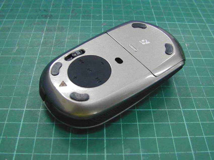
Click to zoom
Application Details
- Equipment Class
- DTS - Digital Transmission System
- Date of Grant
- Sep 26, 2007
- Application Purpose
- Original Equipment
- Date of Application
- Aug 21, 2007
- Equipment Note
- Wireless Mouse
- Frequency Range
- 2402.00000000 - 2474.00000000
- Company
- ACCO Brands, Inc.
- Country
- United States
Documents & Files
Document Text
Text extracted from the exhibit documents filed with the FCC. Open a document above to read the original.
Users Manual
Contents Slim B la de ™ P r e se n t er Medi a Mo u se SlimBlade ™ Presenter Media Mouse INSTRUCTION GUIDE 901-2102-00 Technical Support België / Belgique 02 275 0684 Canada 1 800 268 3447 Denmark 35 25 87 62 Deutschland 0211 6579 1159 España 91 662 38 33 Finland 09 2290 6004 France 01 70 20 00 41 Hungary 20 9430 612 Ireland 01 601 1163 Italia 02 4827 1154 México 55 15 00 57 00 Nederland 053 482 9868 Norway 22 70 82 01 Österreich 01 790 855 701 Portugal 800 831 438 Schweiz / Suisse 01 730 3830 Sweden 08 5792 9009 United Kingdom 0207 949 0119 United States 1 800 535 4242 International Toll +31 53 484 9135 Kensington Computer Products Group A Division of ACCO Brands 333 Twin Dolphin Drive, Sixth floor Redwood Shores, CA 94065 Designed in California, U.S.A. by Kensington Made in China ACCO Brands Europe Oxford Road Aylesbury Bucks, HP21 8SZ United Kingdom ACCO Canada Inc. 5 Precidio Court Brampton Ontario L6S 6B7 Canada ACCO Australia Level 2, 8 Lord St Botany NSW 2019 PO Box 311 Rosebery NSW 1445 Australia www.kensington.com Patents Pending 2 3 Battery indicator 1 Install batteries A Plug in the USB receiver 2 The wireless connection is made automatically 30 ft or 10 m max. In line of sight No direct line of sight required AB Once batteries are installed and a wireless connection is made, the green LED will stay solid for 5 seconds at start up. If there is connection but the battery is weak, the LED will flash red for 5 seconds. If the battery gets weak in the middle of use, the LED will also flash red. LED will also light up when the Receiver is removed from the mouse to start up. Note: Please use fresh non-rechargeable alkaline batteries. We recommend that you use same brand of batteries. 3 Install the Driver Software For PC Users - this driver will allow you to have 4 way tilt scroll control For Mac Users - this driver will allow you to use the D-Pad under the mouse to control iTunes B Jogball Functionality This is a 2 Button Mouse with a jogball for 360 degrees scroll (Driver is required for this functionality). Rolling this jogball scrolls the document on screen. The Mouse shuts down when the dongle is stored inside it. 4 5 Mouse/Media Mode and Presenter Mode Functionality The switch to the right of the D-pad toggles between Mouse/Media Mode and Presenter Mode. Mouse/Media Mode To use as a mouse or media controller, keep switch in down position, indicated by musical note . Presenter Mode To use in Presenter Mode to control a slide presentation, keep switch in up position, indicated by presentation screen. To activate the laser pointer, press . Common Troubleshooting Steps 1. Un-plug and re-plug the receiver. 2. Install fresh batteries in the mouse 3. Test the device on another port or computer. 4. Some surfaces may “trick” the sensor, such as reflective surfaces like glass or mirrors. As a result this product will not work well on glass or mirror surfaces. The sensor should perform well on all other surfaces. IMPORTANT: Computer User Health Information In recent years, medical attention on occupational injuries has identified normal, seemingly harmless activities as a potential cause of a wide range of problems collectively known as Repetitive Stress Injuries (RSI) or Cumulative Trauma Disorders (CTD). It is now recognized that any repetitive motion may contribute to these health problems. As a computer user, you might also be at risk. By paying attention to the way you perform your work, use your computer and phone, play sports, and work around the house, you can identify the behaviors that may be putting you at risk. If you experience pain, swelling, numbness, or weakness in your wrists or hands (especially during sleep), see your physician immediately. These symptoms could mean that you are developing a repetitive stress injury that requires prompt medical attention. For more detailed information, consult your doctor. Technical Support Technical support is available to all registered users of Kensington products. There is no charge for technical support except the cost of the phone call, and long distance charges where applicable. Technical Support Contact information can be found on the back page of this manual. Technical Support Tips • You may find the answer to your problem in the Frequently Asked Questions (FAQ) section of the Support area on the Kensington Website: www.support.kensington.com. • Call from a phone where you have access to your computer • Be prepared to provide the following information: - Name, address, and telephone number - The name of the Kensington product - Make and model of your computer - Your system software and version - Symptoms of the problem and what led to them CLASS 1 AND CLASS 2 LASER SAFETY STATEMENT: This device complies with international standard IEC 60825-1: 2001-08, class 1 and class 2 laser products and also Comply with 21 CFR 1040.10 and 1040.11 except for deviation pursuant to Laser Notice No. 50 dated 7/2001. Operating temperate: between 0 ° C (32° F) to 40° C (104° F). CAUTION: This device has no serviceable parts. Use of controls or adjustments or performance of procedures other than those specified herein may result in hazardous radiation exposure. Presenter Mode Laser pointer Blank screen/Resume screen Previous slide Next slide Starts presentation Volume up Volume down Previous track Next track Mouse/Media Mode Play/Pause 6 7 FCC RADIATION EXPOSURE STATEMENT This equipment complies with FCC radiation exposure limits set forth for an uncontrolled environment. End users must follow the specific operating instructions for satisfying RF exposure compliance. This transmitter must not be co-located or operating in conjunction with any other antenna or transmitter. FEDERAL COMMUNICATIONS COMMISSION RADIO FREQUENCY INTERFERENCE STATEMENT Note: This device has been tested and found to comply with the limits for a Class B digital device, pursuant to Part 15 of the FCC Rules. These limits are designed to provide reasonable protection against ha…
Text truncated - open the document above for the full version.
Cover Letter(s)
American Telecommunications Certification Body Inc. 6731 Whittier Ave, McLean, VA 22101 October 24, 2008 TO: Federal Communications Commission RE: Request for placement into audit status and supersede of label for FCC ID: GV3M01003-M Please place this application in audit status so that we may supercede the original label from 9/2/07. The applicant decided to take off the two plastic strips attached between battery cover and product body and relocate FCC ID label from middle of compartment to left side in the future production of this model. Thank you. Marianne Bosley American TCB Inc. Direct 717-676-3203
External Photos
Photo 1: External photo of EUT M01003-M Photo 2: External photo of EUT M01003-M Photo 3: External photo of EUT M01003-M
ID Label/Location Info
FCC ID:GV3M01003-M Class 2 Laser Product IC: 6128A-M01003M M/N: M01003-M *18mm *4mm *18mm *4mm 1:1 1:1 3:13:1 IC: 6128A-M01003M M/N: M01003-M FCC ID:GV3M01003-M Class 2 Laser Product FCC ID LABEL IC ID LABEL
Internal Photos
Photo 1: Internal photo of EUT M01003-M Photo 2: Internal photo of EUT M01003-M Photo 3: Internal photo of EUT M01003-M Photo 4: Internal photo of EUT M01003-M Photo 5: Internal photo of EUT M01003-M Photo 6: Internal photo of EUT M01003-M Photo 7: Internal photo of EUT M01003-M Photo 8: Internal photo of EUT M01003-M Photo 9: Internal photo of EUT M01003-M Photo 10: Internal photo of EUT M01003-M
RF Exposure Info
FCC ID.: GV3M01003-M Report No.: EME-070793 Page 1 of 5 Maximum Permissible Exposure (MPE) Evaluation Report Report No. : EME-070793 Model No. : M01003-M Issued Date : Aug. 14, 2007 Applicant : ACCO BRANDS, INC 333 Twin Dolphin Drive, Sixth Floor, Redwood Shores, CA94065, USA Test By : Intertek Testing Services Taiwan Ltd. No. 11, Lane 275, Ko-Nan 1 Street, Chia-Tung Li, Shiang-Shan District, Hsinchu City, Taiwan This test report consists of 5 pages in total. It may be duplicated completely for legal use with the allowance of the applicant. It shall not be reproduced except in full, without the written approval of Intertek Laboratory. The test result(s) in this report only applies to the tested sample(s). Jimmie Liu Project Engineer Reviewed By Kevin Chen FCC ID.: GV3M01003-M Report No.: EME-070793 Page 2 of 5 Table of Contents Summary of Tests ............................................................................................................. 3 1. Introduction .................................................................................................................. 4 2. RF Exposure Limit ....................................................................................................... 4 3. RF Exposure calculations ............................................................................................. 5 FCC ID.: GV3M01003-M Report No.: EME-070793 Page 3 of 5 Summary of Tests MPE Evaluation meet FCC OET No. 65: 1997/ IEEE C95.1-1999 Kensington ® SlimBlade TM Presenter Media Mouse -Model: M01003-M FCC ID: GV3M01003-M Test Reference Results MPE Evaluation FCC Guidelines for Human Exposure IEEE C95.1 Pass FCC ID.: GV3M01003-M Report No.: EME-070793 Page 4 of 5 1. Introduction The EUT operates in the 2.4GHz ISM band. Due to the EUT (include antenna) at its normal operation distance is near by the human body (assume 0.1cm), the EUT was defined as a Portable Device. The reason to do the MPE Evaluation is to avoid the RF hazard to human body. The maximum output power and gain of the antenna were used to calculate the limited distance from the product. The limit for Maximum Permissible Exposure (MPE) specified in FCC 1.1310 is followed. This a portable/mobile device and the max peak output power is -0.52dBm (0.99 W). Lower that low threshold 60/f GHz mW (24.48 mW), d<2.5 cm general population category. 2. RF Exposure Limit According to FCC 1.1310: The criteria listed in the following table shall be used to evaluate the environmental impact of human exposure to radio-frequency (RF) radiation as specified in 1.1307(b). Limits for Maximum Permissible Exposure (MPE) Frequency Range (MHz) Electric Field Strength (V/m) Magnetic Field Strength (A/m) Power Density (mW/cm 2 ) Average Time (minutes) (A) Limits for Occupational / Control Exposures 30-300 61.4 0.163 1.0 6 300-1500 - - F/300 6 1500-100,000 - - 5 6 (B) Limits for General Population / Uncontrolled Exposure 30-300 27.5 0.073 0.2 30 300-1500 - - F/1500 30 1500-100,000 - - 1.0 30 F= Frequency in MHz FCC ID.: GV3M01003-M Report No.: EME-070793 Page 5 of 5 3. RF Exposure calculations From FCC 1.1310 table 1, the maximum permissible RF exposure for an uncontrolled environment is 1mW/(cm 2 ) Power density (S) is calculated by the following formula: S = (P * G)/4πR 2 where, S = Power density (mW/cm 2 ) P = Output power to antenna (mW) R = Distance between radiating structure and observation point (cm) G = Gain of antenna in numeric π = 3.1416 Example: Assume a portable device operates at 2412MHz and its maximum output power is 20mW, and the maximum gain of antenna is 1 (numeric) /0dBi. then the power density (S) = (20 * 1)/4*π*(0.1) 2 = (mW/cm 2 ) 4. Test results Channel Channel Frequency (MHz) Maximum antenna gain (numeric) Output power to antenna (mW) Power density (mW/cm 2 ) Limit of power density (mW/cm 2 ) 0 2402 0.77 0.74 0.00011 1.0 6 2438 0.77 0.97 0.00015 1.0 12 2474 0.77 0.99 0.00015 1.0 The Notice in Installation Manual has been stated as below: While installing and operating this transmitter, the radio frequency exposure limit of 1mW/(cm*cm) may be exceeded at distances close to the transmitter. therefore, the user must maintain a minimum distance of 20 cm from the device at all time.
Test Report
FCC ID. : GV3M01003-M Report No.: EME-070793 Page 1 of 37 EMC TEST REPORT Report No. : EME-070793 Model No. : M01003-M Issued Date : Aug. 14, 2007 Applicant : ACCO BRANDS, INC 333 Twin Dolphin Drive, Sixth Floor, Redwood Shores, CA94065, USA Test By : Intertek Testing Services Taiwan Ltd. No. 11, Lane 275, Ko-Nan 1 Street, Chia-Tung Li, Shiang-Shan District, Hsinchu City, Taiwan This test report consists of 37 pages in total. It may be duplicated completely for legal use with the allowance of the applicant. It shall not be reproduced except in full, without the written approval of Intertek Laboratory. The test result(s) in this report only applies to the tested sample(s). Kevin Chen Project Engineer Reviewed By Jimmie Liu FCC ID. : GV3M01003-M Report No.: EME-070793 Page 2 of 37 Table of Contents Summary of Tests ..............................................................................................................3 1. General information ......................................................................................................4 1.1 Identification of the EUT........................................................................................4 1.2 Additional information about the EUT...................................................................4 1.3 Antenna description ................................................................................................4 2. Test specifications .........................................................................................................5 2.1 Test standard ...........................................................................................................5 2.2 Operation mode ......................................................................................................5 2.3 Test equipment........................................................................................................6 3. Minimum 6dB Bandwidth test ......................................................................................7 3.1 Operating environment ...........................................................................................7 3.2 Test setup & procedure ...........................................................................................7 3.3 Measured data of Minimum 6dB Bandwidth test results .......................................7 4. Maximum Output Power test ......................................................................................11 4.1 Operating environment .........................................................................................11 4.2 Test setup & procedure .........................................................................................11 4.3 Measured data of Maximum Output Power test results .......................................11 5. RF Antenna Conducted Spurious test..........................................................................12 5.1 Operating environment .........................................................................................12 5.2 Test setup & procedure .........................................................................................12 5.3 Measured data of the highest RF Antenna Conducted Spurious test result..........12 6. Radiated Emission test ................................................................................................22 6.1 Operating environment .........................................................................................22 6.2 Test setup & procedure .........................................................................................22 6.3 Emission limits .....................................................................................................23 6.4 Radiated spurious emission test data ....................................................................24 6.4.1 Measurement results: frequencies equal to or less than 1 GHz .........................24 6.4.2 Measurement results: frequency above 1GHz...................................................25 7. Power Spectrum Density test ......................................................................................28 7.1 Operating environment .........................................................................................28 7.2 Test setup & procedure .........................................................................................28 7.3 Measured data of Power Spectrum Density test results .......................................28 8. Emission on the band edge..........................................................................................32 8.1 Operating environment .........................................................................................32 8.2 Test setup & procedure .........................................................................................32 8.3 Test Result ............................................................................................................33 8.3.1 Radiated Method ...............................................................................................34 FCC ID. : GV3M01003-M Report No.: EME-070793 Page 3 of 37 Summary of Tests Kensington ® SlimBlade TM Presenter Media Mouse -Model: M01003-M FCC ID: GV3M01003-M Test Reference Results Minimum 6dB Bandwidth test 15.247(a)(2) Pass Maximum Output Power test 15.247(b) Pass RF Antenna Conducted Spurious test 15.247(d) Pass Radiated Spurious Emission test 15.205, 15.209 Pass Power Spectrum Density test 15.247(e) Pass Emission on the Band Edge test 15.247(d) Pass FCC ID. : GV3M01003-M Report No.: EME-070793 Page 4 of 37 1. General information 1.1 Identification of the EUT Applicant : ACCO BRANDS, INC Product : Kensington ® SlimBlade TM Presenter Media Mouse Model No. : M01003-M FCC ID. : GV3M01003-M Frequency Range : 2402MHz ~ 2474MHz Channel Number : 13 channels Frequency of Each Channel : 2402 + 6k MHz; k = 0-12 Type of Modulation : GFSK Rated Power : DC 1.5V from Battery Powe…
Text truncated - open the document above for the full version.
Test Setup Photos
Photo 1: Radiated Emission Test set-up photo M01003-M Photo 2: Radiated Emission Test set-up photo M01003-M
Contact Information
Applicant
Benjamin Hsu(Compliance Manager)
Technical Contact
Intertek Testing Services Taiwan Ltd.Kevin Chen
[email protected]+886-3-519-1411
No. 11, Ko-Tze-Nan Chia-Tung Li, · Taiwan Hsinchu · Taiwan
Test Firm
Intertek Testing Services Taiwan Ltd.Alpha Liu
Technical Specifications
| # | Rule Parts | Frequency Range | Power Output |
|---|---|---|---|
| 1 | 15C | 2.40 GHz - 2.47 GHz | 1.00 mW |
Other Applications from ACCO Brands, Inc.
GV3M01709-K
Nov 28, 2024KB270 EQ Rechargeable Keyboard
Equipment Class
DTS - Digital Transmission SystemGV3M01500-MA
Jan 28, 2024Kensington Vertical Wireless Mouse
Equipment Class
DSS - Part 15 Spread Spectrum Transmitter
GV3M01687-M
Sep 17, 2023MY430 Rechargeable Mouse
Equipment Class
DTS - Digital Transmission System
GV3M01702-P
Sep 17, 2023Wireless Presenter with Red Laser-Nano Receiver
Equipment Class
DSS - Part 15 Spread Spectrum Transmitter
GV3M01440-KB
Aug 24, 2023Pro Fit Ergo Wireless Keyboard
Equipment Class
DSS - Part 15 Spread Spectrum Transmitter