GV3M01435-DSureTrack Dual Wireless Dongle
ACCO Brands, Inc.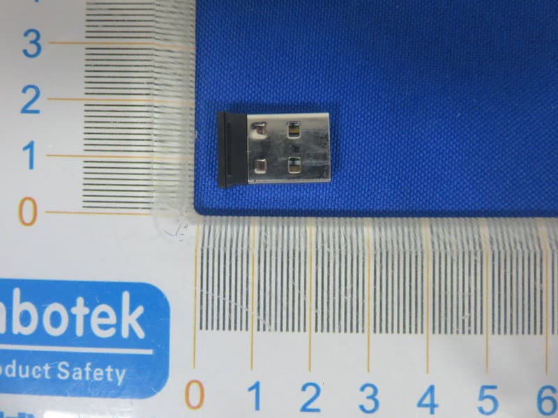
Click to zoom
Application Details
- Equipment Class
- DXT - Part 15 Low Power Transceiver, Rx Verified
- Date of Grant
- Apr 14, 2020
- Application Purpose
- Original Equipment
- Date of Application
- Apr 14, 2020
- Equipment Note
- SureTrack Dual Wireless Dongle
- Frequency Range
- 2403.00000000 - 2480.00000000
- Company
- ACCO Brands, Inc.
- Country
- United States
Documents & Files
Document Text
Text extracted from the exhibit documents filed with the FCC. Open a document above to read the original.
Users Manual
K75298_SureTrack™ Dual Wireless Mouse_IG Folded size: 95 mm X 140 mm Trim size: 665mm X 140 mm K75298/ K75350/ K75351/ K75352/ K75353901-0022-00 1 2 A Left Button / Bouton gauche / Linke Maustaste / Linkerknop / Bal gomb / Levé tlačítko / Tasto sinistro / Botón izquierdo / Lewy przycisk / Левая кнопка / Botão para a Esquerda / 左键/ / B Right Button / Bouton droit / Rechte Maustaste / Rechterknop / Jobb gomb / Pravé tlačítko / Tasto destro / Botón derecho / Prawy przycisk / Правая кнопка / Botão para a Direita / 右键/ / D Status Indicator / Indicateur d’état / Statusanzeige / Statusindicator / Indicatore di stato/ Indicador de estado / Állapotjelző fény / SIndikátor stavu / Wskaźnik stanu / индикатор состояния / Indicador de estado / 状态指示灯 / / E 2.4GHz/Bluetooth Switch / Commutateur 2,4 GHz/Bluetooth / 2,4 GHz / Bluetooth-Umschalter / 2,4 GHz/bluetooth-schakelaar / 2,4 GHz-es/Bluetooth kapcsoló / Přepínač připojení 2,4 GHz / Bluetooth / 2,4 GHz / „Bluetooth“ perjungimas / Interruptor Bluetooth/2,4 GHz / Przełącznik 2,4 GHz/Bluetooth / 2,4 ГГц/Bluetooth-переключатель / Comutador Bluetooth/2,4 GHz / 2.4GHz/蓝牙切换 / / EN IMPORTANT: Computer User Health Information Use of a keyboard, mouse, or trackball may be linked to serious injuries or discomfort. Recent medical research of occupational Injuries has linked normal, seemingly harmless activities as a potential cause of Repetitive Stress Injuries (“RSI”). Many factors may be linked to the occurrence of RSI, including a person’s own medical and physical condition, overall health, and how a person positions and uses his or her body during work and other activities (including use of a keyboard, mouse, or trackball). Some studies suggest that the amount of time a person uses a keyboard, mouse, or trackball may also be a factor. Consult a qualified health professional for any questions or concerns you may have about these risk factors. When using a keyboard, mouse, or trackball, you may experience occasional discomfort in your hands, arms, shoulders, neck, or other parts of your body. However, if you experience symptoms such as persistent or recurring discomfort, pain, throbbing, aching, tingling, numbness, burning sensation, or stiffness, even if such symptoms occur while you are not working at your computers. DO NOT IGNORE THESE WARNING SIGNS. PROMPTLY SEE A QUALIFIED HEALTH PROFESSIONAL. These symptoms can be signs of sometimes permanently disabling RSI disorders of the nerves, muscles, tendons, or other parts of the body. • When the batteries are dead, replace all batteries from the product at the same time with the correct size and type of batteries. • Keep batteries away from children. • Do not misuse, damage, disassemble or modify the batteries. CAUTION: Never spray liquid cleaner directly on the trackball RF TECHNICAL SPECIFICATION Operating Frequency Range: 2402~2480MHz Maximum RF Output Power: max 0dBm SAFETY AND USAGE GUIDELINES 1. In the absence of proper operation and if customer-initiated troubleshooting is unsuccessful, switch off device and contact Kensington technical support: www.kensington.com 2. Do not disassemble product or expose it to liquid, humidity, moisture, or temperatures outside the specified operating ranges of 0° C (32° F) to 40° C (104° F). 3. If your product is exposed to out-of-range temperatures, switch it off and allow temperature to return to the normal operating range. DIRECTIVES DE SÉCURITÉ ET D’UTILISATION 1. En cas de mauvais fonctionnement et si le dépannage entamé par le client s’avère infructueux, éteindre le dispositif et appeler l’assistance technique de Kensington. www.kensington.com. 2. Ne pas démonter le produit ou le faire entrer en contact avec des liquides, l’exposer à l’humidité ou à des températures sortant des plages opérationnelles spécifiées, qui vont de 0° C à 40° C. 3. Si votre produit est exposé à des températures extrêmes, l’éteindre et laisser la température revenir à la plage opérationnelle normale. DE WICHTIG: Gesundheitshinweise für Computerbenutzer Die Benutzung von Tastatur, Maus oder Trackball kann zu schweren Verletzungen oder Beschwerden führen. Neuere medizinische Untersuchungen zu Arbeitsunfällen sehen normale, scheinbar harmlose Aktivitäten als mögliche Ursache für Überlastungssyndrome. Beim Auftreten von Überlastungssyndromen können viele Faktoren zusammenspielen: Hier sind beispielsweise die medizinische und körperliche Verfassung einer Person, ihre allgemeine Gesundheit sowie die Körperhaltung bei der Arbeit und anderen Aktivitäten (einschließlich der Verwendung von Tastatur, Maus oder Trackball) zu nennen. Einige Studien legen nahe, dass auch die Dauer der Benutzung von Tastatur, Maus oder Trackball ein Faktor sein kann. Wenden Sie sich bei Fragen oder Bedenken bezüglich dieser Risikofaktoren an qualifizierte medizinische Fachkräfte. Bei der Benutzung von Tastatur, Maus oder Trackball kann es gelegentlich zu Beschwerden in Händen, Armen, Schultern, Nacken oder anderen Körperteilen kommen. Wenn Sie jedoch Symptome wie anhaltende oder wiederkehrende Beschwerden, Schmerzen, Pochen, Ziehen, Kribbeln, Taubheitsgefühl, Brennen oder Steifheit spüren, selbst wenn Sie nicht am Computer arbeiten, dann: IGNORIEREN SIE DIESE WARNSIGNALE NICHT. SUCHEN SIE UMGEHEND EINE QUALIFIZIERTE MEDIZINISCHE FACHKRAFT AUF. Diese Symptome können Anzeichen für Überbelastungen von Nerven, Muskeln, Sehnen oder anderer Körperteilen sein, die zu dauerhaften Behinderungen führen können. • Wenn die Batterien leer sind, ersetzen Sie sämtliche Batterien aus dem Produkt gleichzeitig durch neue Batterien der richtigen Größe und Art. • Halten Sie Batterien von Kindern fern. • Batterien dürfen nicht zweckentfremdet, beschädigt, zerlegt oder modifiziert werden. VORSICHT: Sprühen Sie den Reiniger nicht direkt auf den Trackball. TECHNISCHE RF-SPEZIFIKATIONEN Betriebsfrequenzbereich: 2402~2480MHz Maximale HF-Ausgangsleistung: max 0dBm NL BELANGRIJK: gezondheidsinformatie voor computergebruikers Gebruik van een toetsen…
Text truncated - open the document above for the full version.
External Photos
FCC ID: GV3M01435-D
ID Label/Location Info
Label Location On EUT Label FCC ID: GV3M01435-D
Internal Photos
FCC ID: GV3M01435-D ANT
Operational Description
version01 ACCO Brands, Inc. Declaration concerning Antenna Specification It is hereby declared that the product Model No.: M01435-D FCC ID : GV3M01435-D fulfills the requirement in FCC test relating to the antenna type. The device specified above confirms to the FCC recommendations for internal antenna type(s) described below: 2.4GHz Model No. of antenna: N/A Type of antenna:PCB Antenna Gain of the antenna: -1.66 dBi Frequency range:2403~2480MHz The mounting of the antenna is fixed to the radio module and no other antenna should be used. Company name: ACCO Brands, Inc. Address: 1500 Fashion Island Blvd., 3rd Floor, San Mateo, CA94404, United States City: San Mateo, CA94404 ZIP / Postal code: Country:United States Place:United StatesDate: 2020-04-13 Signature:
RF Exposure Info
RFEXPOSUREEVALUATION EUTSpecification EUTSureTrackDualWirelessDongle ModelNameM01435-D Frequencyband (Operating) WLAN:2.412GHz~2.462GHz WLAN:5.18GHz~5.32GHz/5.50GHz~5.70GHz WLAN:5.745GHz~5825GHz Others:2403 ‐ 2480MHz DevicecategoryPortable(<20cmseparation) Mobile(>20cmseparation) Others___ AntennadiversitySingleantenna Multipleantennas Txdiversity Rxdiversity Tx/Rxdiversity Max.outputpower93.13dBuV/m(-2.128dBm)(0.613mW) Antennagain-1.66dBi EvaluationappliedMPEEvaluation SAREvaluation StandardRequirement PortableDevice Accordingto§15.247(i)and§1.1307b(1),systemsoperatingundertheprovisionsofthissection shallbeoperatedinamannerthatensuresthatthepublicisnotexposedtoradiofrequency energylevelsinexcessoftheCommission’sguidelines.SeeKDB447498D01GeneralRF ExposureGuidanceV6,section4.3.1. The1-gand10-gSARtestexclusionthresholdsfor100MHzto6GHzattestseparation distances≤50mmaredeterminedby: [(max.powerofchannel,includingtune-uptolerance,mW)/(min.testseparationdistance, mm)]·[√f(GHz)]≤3.0for1-gSARand≤7.5for10-gextremitySAR, 16 where ·f(GHz)istheRFchanneltransmitfrequencyinGHz ·PoweranddistanceareroundedtothenearestmWandmmbeforecalculation17 ·Theresultisroundedtoonedecimalplaceforcomparison Thetestexclusionsareapplicableonlywhentheminimumtestseparationdistanceis≤50 mmandfortransmissionfrequenciesbetween100MHzand6GHz.Whentheminimumtest separationdistanceis<5mm,adistanceof5mmisappliedtodetermineSARtestexclusion. MeasurementResult Channel Frequency (MHz) MaxOutput power (dBm) Tuneup tolerance (dBm) MaxTune UpPower (dBm) Distanc e(mm) Calculati onValue (Note1) Threshold Value 2441-2.128±1-1.12850.2413.0 EIRP=E-104.8+20logD=93.13-104.8+20log3=-2.128dbm Note1:CalculationValue=[(max.powerofchannel,includedTuneup tolerance,mW)/(min.testseparationdistance,mm)]·[√f(GHz)]. Foxexample:0.771/5*√2.441=0.241≤3.0 AccordingtoKDB447498D01V6,thresholdatwhichnoSARrequiredis≤3.0for1-gSAR, separationdistanceis5mm,andnosimultaneousSARmeasurementisrequired. TheSARmeasurementisnotnecessary.
Test Report
Report No.: 18220WC00012901FCC ID: GV3M01435-DPage 1 of 39 Code:AB-RF-05-a FCC TEST REPORT Client Name: ACCO Brands, Inc Address: 1500 Fashion Island Blvd., 3rd Floor, San Mateo, CA 94404, USA Product Name: SureTrack Dual Wireless Dongle Date: Apr. 13, 2020 Shenzhen Anbotek Compliance Laboratory Limited Report No.: 18220WC00012901FCC ID: GV3M01435-DPage 2 of 39 Code:AB-RF-05-a Contents 1. General Information ............................................................................................................................................... 4 1.1. Client Information ....................................................................................................................................... 4 1.2. Description of Device (EUT) ..................................................................................................................... 4 1.3. Auxiliary Equipment Used During Test ................................................................................................... 5 1.4. Description of Test Modes ........................................................................................................................ 5 1.5. List of Channels .......................................................................................................................................... 6 1.6. Description of Test Setup .......................................................................................................................... 7 1.7. Test Equipment List .................................................................................................................................... 8 1.8. Measurement Uncertainty ......................................................................................................................... 9 1.9. Description of Test Facility ........................................................................................................................ 9 2. Summary of Test Results ................................................................................................................................... 10 3. Conducted Emission Test ................................................................................................................................... 11 3.1. Test Standard and Limit .......................................................................................................................... 11 3.2. Test Setup .................................................................................................................................................. 11 3.3. Test Procedure .......................................................................................................................................... 11 3.4. Test Data .................................................................................................................................................... 12 4. Radiated Emission and Band Edge .................................................................................................................. 15 4.1. Test Standard and Limit .......................................................................................................................... 15 4.2. Test Setup .................................................................................................................................................. 16 4.3. Test Procedure .......................................................................................................................................... 17 4.4. Test Data .................................................................................................................................................... 18 5. 20dB Bandwidth Test .......................................................................................................................................... 28 5.1. Test Standard and Limit .......................................................................................................................... 28 5.2. Test Setup .................................................................................................................................................. 28 5.3. Test Procedure .......................................................................................................................................... 28 5.4. Test Data .................................................................................................................................................... 28 6. Antenna Requirement ......................................................................................................................................... 31 6.1. Test Standard and Requirement ............................................................................................................ 31 6.2. Antenna Connected Construction .......................................................................................................... 31 APPENDIX I -- TEST SETUP PHOTOGRAPH ................................................................................................... 32 APPENDIX II -- EXTERNAL PHOTOGRAPH ..................................................................................................... 34 APPENDIX III -- INTERNAL PHOTOGRAPH ..................................................................................................... 37 Report No.: 18220WC00012901FCC ID: GV3M01435-DPage 3 of 39 Code:AB-RF-05-a TEST REPORT Applicant: ACCO Brands, Inc Manufacturer: ACCO Brands, Inc Product Name: SureTrack Dual Wireless Dongle Model No.: M01435-D Trade Mark: Kensington Rating(s): Input: DC 5V, 50mA Test Standard(s) : FCC Part15 Subpart C, Paragraph 15.249 Test Method(s): ANSI C63.10: 2013 The device described above is tested by Shenzhen Anbotek Compliance Laboratory Limited to determine the maximum emission levels emanating from the device and the severe levels of the device can endure and its perfor…
Text truncated - open the document above for the full version.
Test Setup Photos
FCC ID: GV3M01435-D Photo of Conducted Emission Test Photo of Radiation Emission Test
Contact Information
Applicant
Benjamin Hsu(Compliance Manager)
Test Firm
Shenzhen Anbotek Compliance Laboratory LimitedJeff Zhu
Technical Specifications
| # | Rule Parts | Frequency Range | Power Output |
|---|---|---|---|
| 1 | 15C | 2.40 GHz - 2.48 GHz | 700.00 µW |
Other Applications from ACCO Brands, Inc.
GV3M01709-K
Nov 28, 2024KB270 EQ Rechargeable Keyboard
Equipment Class
DTS - Digital Transmission SystemGV3M01500-MA
Jan 28, 2024Kensington Vertical Wireless Mouse
Equipment Class
DSS - Part 15 Spread Spectrum Transmitter
GV3M01687-M
Sep 17, 2023MY430 Rechargeable Mouse
Equipment Class
DTS - Digital Transmission System
GV3M01702-P
Sep 17, 2023Wireless Presenter with Red Laser-Nano Receiver
Equipment Class
DSS - Part 15 Spread Spectrum Transmitter
GV3M01440-KB
Aug 24, 2023Pro Fit Ergo Wireless Keyboard
Equipment Class
DSS - Part 15 Spread Spectrum Transmitter